i
FLUID FLOW CHARACTERISTIC IN CURVED TUBE HEAT EXCHANGER BY NUMERICAL METHOD
SYAZWAN BIN ZAINUDDIN
This thesis is submitted to Mechanical Engineering Faculty in partial fulfillment of the requirements for the award of Bachelor Degree in Mechanical Engineering
(Thermal-Fluid)
Faculty of Mechanical Engineering Universiti Teknikal Malaysia Melaka
ii
DECLARATION
“I hereby declared that this report is a result of my own work except for the works that have been cited clearly in the references.”
Signature : ……… Name : Syazwan Bin Zainuddin
iii
Special dedicate to
iv
ACKNOWLEDGEMENT
Assalamualaikum .. I give thanks to Allah swt for His blessings and grace, can I run the program and complete the Projek Sarjana Muda II report without hindrance and can solve everything very well when I was 15 weeks at the plant.
v
ABSTRACT
Due to the enormous heat generated in the internal combustion engine of a motor vehicle, a cooling system must be included. For compact and aerodynamic cars design affect the air flow rate through the radiator and need the design of compact radiator. The radiator is device used to cool the engine. In any cooling system of a motor vehicle, a redesigned the radiator can give the better performance. This report examines fluid flow characteristics in curved tubes heat exchanger by numerical method. This project will investigate the result for the curved tube radiator and compare to result from existing radiator. The method of this study for the collecting data and analyze by numerical method. By using the Computational Fluid Dynamic (CFD) software the modeling of fluid flow in tube was developed for computation simulation. Aided by the developed software, the characteristic of fluid flow will be investigated. Besides that, this study will be carried out by using experimental data for evaluating the working performance of different types of radiator. Therefore, performance data of automotive radiator were acquired and analyzed to improve available radiator performance.
vi
ABSTRAK
Oleh kerana haba yang besar terhasil di dalam enjin pembakaran dalaman kenderaan motor, sistem penyejukan harus disertakan. Bagi reka bentuk kereta kompak dan aerodinamik mempengaruhi kadar aliran udara melalui radiator dan memerlukan reka bentuk radiator padat. Radiator adalah alat yang digunakan untuk menyejukkan enjin. Dalam mana-mana sistem penyejukan kenderaan bermotor, direka semula radiator boleh memberikan prestasi yang lebih baik. Laporan ini mengkaji ciri-ciri aliran cecair dalam tiub melengkung penukar haba dengan kaedah berangka. Projek ini akan mengkaji hasil untuk radiator tiub melengkung dan membandingkan hasil dari radiator yang sedia ada. Kaedah kajian ini untuk mengumpul data dan menganalisis dengan kaedah berangka. Dengan menggunakan Bendalir Komputeran Dynamic (CFD) perisian model aliran bendalir dalam tiub telah dibangunkan untuk simulasi pengiraan. Dibantu oleh perisian yang dibangunkan, ciri-ciri aliran bendalir akan disiasat. Selain itu, kajian ini akan dijalankan dengan menggunakan data eksperimen untuk menilai prestasi kerja jenis radiator. Oleh itu, data prestasi radiator automotif telah diperolehi dan dianalisis untuk meningkatkan prestasi radiator ada.
vii
CONTENTS
CHAPTER ITEMS PAGE
Declaration ii
Acknowledgement iv
Abstract v
Abstrak vi
Table of content vii
List of figure ix
I INTRODUCTION 1
1.1 Overview 1
1.2 Problem Statement 2
1.3 Objective of Study 3
1.4 Scope of Study 3
II LITERATURE REVIEW 4
2.1 Engine Cooling System 8
2.2 Cooling System Function 11
2.3 Types Of cooling System 11
2.3.1 Air Cooling 11
2.3.2 Liquid Cooling System 12
2.4 Working Radiator 12
2.5 Theory of Radiator 14
2.5.1 Pressure Cap 15
2.5.2 Radiator Fan 16
2.6 Definition and Theory of CFD 17
viii
2.6.2 Validation of CFD model 18
2.6.3 Advantaged of CFD 19
III METHODOLOGY 20
3.1 Introduction 20
3.2 Pre-Procedure 21
3.2.1 Initial Thinking 22
3.2.2 Geometry Creation 22
3.2.3 Mesh Generation 22
3.2.4 Flow Specification 23
3.2.5 Calculation of the Numerical Solution 23
3.2.6 Result Analysis 23
3.3 Study of Planning 24
3.3.1 Flowchart 24
3.3.2 Scope of Simulation 26
3.3.3 Geometry 26
3.3.4 Mesh 26
IV RESULT 32
4.0 Introduction 32
V DISCUSSION 53
VI CONCLUSION 55
6.0 Conclusion 55
6.1 Recommendation 56
REFERENCES 58
BIBLIOGRAPHY 59
ix
LIST OF FIGURE
Fig. ITEM PAGE
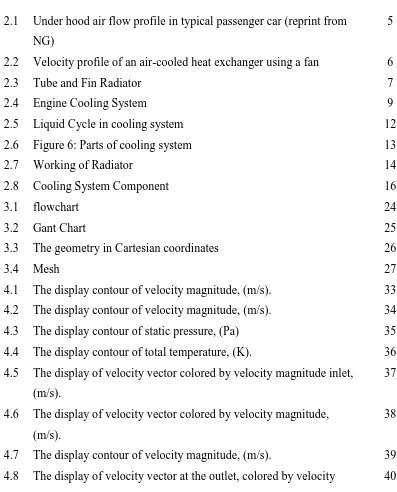
2.1 Under hood air flow profile in typical passenger car (reprint from NG)
5
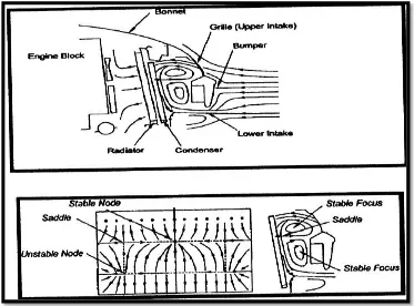
2.2 Velocity profile of an air-cooled heat exchanger using a fan 6
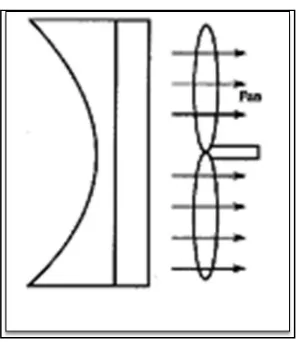
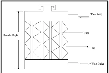
2.3 Tube and Fin Radiator 7
2.4 Engine Cooling System 9
2.5 Liquid Cycle in cooling system 12
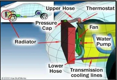
2.6 Figure 6: Parts of cooling system 13
2.7 Working of Radiator 14
2.8 Cooling System Component 16
3.1 flowchart 24
3.2 Gant Chart 25
3.3 The geometry in Cartesian coordinates 26
3.4 Mesh 27
4.1 The display contour of velocity magnitude, (m/s). 33 4.2 The display contour of velocity magnitude, (m/s). 34 4.3 The display contour of static pressure, (Pa) 35 4.4 The display contour of total temperature, (K). 36 4.5 The display of velocity vector colored by velocity magnitude inlet,
(m/s).
37
4.6 The display of velocity vector colored by velocity magnitude, (m/s).
38
x
magnitude, (m/s).
4.9 The display contour of velocity magnitude, (m/s). 41 4.10 The display of velocity vector colored by velocity magnitude inlet,
(m/s).
42
4.11 Contour of velocity magnitude, (m/s). 43 4.12 The display contour of total temperature,(K). 43 4.13 The display contour of total pressure,(Pa). 44 4.14 The contour of velocity magnitude, (m/s). 44 4.15 The contour of static temperature, (K). 45 4.16 The contour of total pressure, (Pa). 45 4.17 The display velocity vector of first tube from inlet colored by
velocity magnitude, (m/s).
46
4.18 The display velocity vector of middle tube colored by velocity magnitude, (m/s).
46
4.19 The display velocity vector of shortest tube colored by velocity magnitude, (m/s).
47
4.20 Graph of residual for curved tube radiator 48 4.21 Graph of residual for square tube radiator 48 4.22 Graph of comparison total pressure, (Pa) for both of radiator. 49 4.23 Graph of comparison total temperature, (K) for both of radiator. 50 4.24 Graph of comparison velocity magnitude, (m/s) for both of
radiator.
51
4.25 Observation of contour velocity profile experimental. 52
A-1 Radiator label. 60
A-2 Radiator with fan. 61
A-3 The velocity vectors colored by static temperature. 62
A-4 Prototype of square radiator. 62
1
CHAPTER I
INTRODUCTION
1.1 Background
2
also highlighting some of its current limitations. It also highlights the need for further research in areas where information is lacking. (Versteeg and Malalasekera, 1996) state the Computational Fluid Dynamics (CFD) is the use of computer-based simulation to analyze systems involving fluid flow, heat transfer and associated phenomena such as chemical reaction a numerical model is first constructed using a set of mathematical equations that describe the flow. These equations are then solved using a computer programmer in order to obtain the flow variables throughout the flow domain. Since the advent of the digital computer, CFD has received extensive attention and has been widely used to study various aspects of fluid dynamics. The development and application of CFD have undergone considerable growth, and as a result it has become a powerful tool in the design and analysis of engineering and other processes. In the early 1980s, computers became sufficiently powerful for general-purpose CFD software to become available.
1.2 Problem Statement
Optimize the design of the existing car radiator to radiator rounded design requires a more detailed analysis of fluid flow in the tube, cooling capacity, heat transfer rate, size, air flow, pressure, and cost.
a. The heat transfer rate must be higher than the existing radiator. At the same time can drain the radiator fan air through all the tubes.
b. Ensure the size of the smaller circular radiator for space saving in the front of the engine in the car.
3
1.3 Objective of the Study
The objectives of this study are:
i. To investigate the characteristic fluid flow in curved tube radiator by using the Computational Fluid Dynamic (CFD) software.
ii. The numerical results are to be compared with experimental
observations of automotive radiator. The experimental data are to be correlated with the numerical parameter of temperature, pressure, and velocity and dimensional.
iii. The characteristic parameters the curved tube radiators are to be determined.
1.4 Scope of the Study
From of this project, the experimental study has been carried out for performance radiator tests by two different type of radiator which square and circular radiator. The scopes of this study are:
i. By using the transparent plastic tubes, metal tubes, conduct flow measurements using laboratory equipment.
4
CHAPTER II
LITERITURE REVIEW
2.1 INTRODUCTION
5
Figure 2.1: under hood air flow profile in typical passenger car (reprint from NG).
From the figure 2.1, observation that air flow shown the non-uniform distributed over the radiator.
6
Figure 2.2: Velocity profile of an air-cooled heat exchanger using a fan.
Khovakh et al, (1977) state, the cooling system is one of the major motor vehicle engine systems that helps ensure the temperature of the engine is kept within the limits imposed for safety and efficiency. The cooling agent customarily employed is air or liquid thus they are air or liquid (water) cooling systems. For effective control of heat in a water cooling system, a “Heat Exchanger” is employed.
7
Bent and Stephens, (1974) and Dolan, (1996) describe the existing literature that the fan contains shrouds and blades, which drawn in air through the radiator thereby reducing the temperature of the water.
Lateef et al, (2004) state the fan increases air flow allowing the use of a smaller radiator, which can dissipate the required amount of heat. The radiator on the other hand, is a vessel that receives and stores heated water from the engine and exposes it to the fan. The matrix of the radiator may be either tube-and-fin type (Figure 1) or film (cellular) type.
Figure 2.3: Tube and fin radiator.
8
2.1 Engine Cooling System
Modern automotive internal combustion engines generate a huge amount of heat. This heat is created when the gasoline and air mixture is ignited in the combustion chamber. This explosion causes the piston to be forced down inside the engine, levering the connecting rods, and turning the crankshaft, creating power. Metal temperatures around the combustion chamber can exceed 1000°F. In order to prevent the overheating of the engine oil, cylinder walls, pistons, valves, and other components by these extreme temperatures, it is necessary to effectively dispose of the heat. It has been stated that a typical average-sized vehicle can generate enough heat to keep a 5-room house comfortably warm during zero degree weather (and not talking about using the exhaust pipe).
Approximately 1/3 of the heat in combustion is converted into power to drive the vehicle and its accessories. Another 1/3 of the heat is carried off into the atmosphere through the exhaust system. The remaining 1/3 must be removed from the engine by the cooling system. Modern automotive engines have basically dumped the Air Cooled System for the more effective Liquid Cooled System to handle the job. In a liquid cooled system, heat is carried away by the use of a heat absorbing coolant that circulates through the engine, especially around the combustion chamber in the cylinder head area of the engine block.
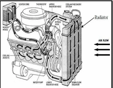
9
Figure 2.4: Engine cooling system.
This engine is cooled by a pressurized water forced circulation cooling system equipped with a thermostatically controlled by pass valve mounted on the inlet side. This engine is cooled by a pressurized water forced circulation cooling system equipped with a thermostatically controlled by pass valve mounted on the inlet side. The operation of cooling system is composed of the water jacket (inside the cylinder block and cylinder head), radiator, water pump, and thermostat, cooling fan, fluid coupling, hoses and other components.
10
The radiator, mounted at the front of vehicle, consists of an upper and lower tank and a core connecting the two tanks. The core contains many tubes through which engine coolant flows from the upper tank to the lower tank. Air passing over the radiator fins cools the heated engine coolant flowing through the radiator. The upper tank has an inlet for engine coolant from the water jacket and it has a filler inlet. It also has a hose attached through which excess engine coolant or steam can flow. The lower tank has an outlet for the engine coolant and a drain cock. Automatic transmission models include an automatic transmission fluid cooler.
The radiator cap is a pressure type cap which seals the radiator, resulting in pressurization of the radiator as the coolant expands. The pressurization prevents the engine coolant from boiling even when the engine coolant temperature exceeds 100°C (212°F). A relief valve (pressurization valve) and a vacuum valve (negative pressure valve) are built into the radiator cap. The relief valve opens and lets steam escape out of the overflow pipe when the pressure generated in the cooling system exceeds the limit (engine coolant temperature: 110 –120°C (230 – 248°F), pressure: 58.8 – 103.0 kPa, 0.6 – 1.05 kgf/cm², 8.5 – 14.9 psi). The vacuum valve opens to allow engine coolant to enter in order to alleviate the vacuum which develops in the engine coolant system after the engine has stopped and the engine coolant temperature drops.
The reservoir tank is used to catch engine coolant which–overflows the cooling system as a result of volumetric expansion when the engine coolant is heated. When the engine coolant temperature drops, engine coolant in the reservoir tank returns to the radiator, thus keeping the radiator full at all times and avoiding needless engine coolant loss. To find out if the engine coolant needs to be replenished, check the reservoir tank level.
The water pump is used for forced circulation of engine coolant through the cooling system. It is mounted on the front of the engine block and driven by the timing belt.
11
permitting the engine to warm up rapidly. When the bypass valve opens the by–pass circuit, the engine coolant continues to circulate inside the engine, quickly and uniformly warming up to the operating temperature. When the engine coolant temperature is high, the valve opens and the engine coolant flows to the radiator where it is cooled. When the wax inside the thermostat is heated, it expands and thus creates pressure which overpowers the force of the spring which keeps the valve closed. When the wax cools, its contraction allows the force of the spring to take effect once more, closing the valve. The thermostat in this engine operates at a temperature of 82°C (180°F).
2.2 Cooling System Function
Randy Rundle, (1999) state that temperatures in the combustion chamber of the engine can reach 4,500°F (2,500°C), so cooling the area around the cylinders is critical. Areas around the exhaust valves are especially crucial, and almost all of the space inside the cylinder head around the valves that is not needed for structure is filled with coolant. If the engine goes without cooling, the metal got hot enough for the piston to weld itself to the cylinder. This usually means the complete destruction of the engine. The cooling system removes enough heat to keep the engine at a safe temperature for best performance. A secondary function of the cooling system is to provide interior cabin heat during cold winter.
2.3 Type of Cooling System
2.3.1 Air Cooling
12
fins, which cools the engine by transferring the heat to the air. Since most cars are liquid-cooled, we will focus on that system in this project.
2.3.2 Liquid Cooling System
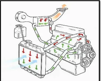
Figure 3 illustrates the cooling system components, and in these sections we'll talk about each part of the system in more detail. Figure 4 illustrates the liquid cycle in the system.
Figure 2.5: Liquid cycle in cooling system.
2.4 Working of Radiator
13
fluid leaves the engine. The plumbing around the thermostat sends the fluid back to the pump directly if the thermostat is closed. If it is open, the fluid goes through the radiator first and then back to the pump.
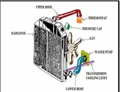
14
Figure 2.7: Working of radiator.
There is also a separate circuit for the heating system. This circuit takes fluid from the cylinder head and passes it through a heater core and then back to the pump. On cars with automatic transmissions, there is normally also a separate circuit for cooling the transmission fluid built into the radiator. The oil from the transmission is pumped by the transmission through a second heat exchanger inside the radiator.
2.5 Theory of Radiator