DEDICATION
TABLE OF CONTENTS
DEDICATION...i
PREFACE...v
1 Overview of database design and relational data model...1
1.1 Theoretical Background...2
1.1.1 Relational Model Design...2
1.1.2 Mapping conceptual design to logical design using relational data model...4
1.2 Exercise...5
1.2.1 Conceptual/Semantic Data Model for Banking Enterprise...5
1.2.2 Logical Database Design for Banking Enterprise...6
1.2.3 Physical Database Design and implementation for Banking Enterprise...6
1.3 Self Review Questions...7
2 Conceptual design : Object oriented data model...8
2.1 Theoretical Background...9
2.2 Exercise...11
2.2.1 Converting relational database tables to the equivalent object-based data model...11
2.2.2 Define business rules for the relationships with objects...12
2.2.3 Identify participation constraints in relationship between objects. 12 2.2.4 Develop object space diagram...12
2.2.5 Define a superclass for object...12
3 Conceptual design : EERD...14
3.1 Theoretical Background...15
3.1.1 Constraints and characteristics of inheritance...15
3.2 Exercise...20
3.2.1 Drawing Enhanced Entity Relationship (EER) data model...20
3.3 Self Review Questions...21
4 Conceptual design : UML (Class Diagram)...22
4.1 Theoretical Background...23
4.2 Exercise...26
4.3 Self Review Questions...27
5 Logical design : Object-relational data model...28
5.1 Theoretical Background...29
5.2 Step-by-step...31
Step 1: Mapping class inheritance tree and abstract class...31
Step 2: Mapping class association...33
Step 3: Mapping class composition...33
Step 4: Creating Object Tables...35
5.3 Exercise...36
5.4 Self Review Questions...37
6 Physical design (Shemal level model) : DDL with SQL3...38
6.1 Theoretical Background...39
6.1.1 Row Type...39
6.1.2 Column type/Abstract Data Type...41
6.2 Exercise...45
6.3 Self Review Questions...46
7 Physical design (Schema level model) : DDL with Oracle...47
7.1 Theoretical Background...48
7.1.1 Object type as column type...48
7.1.3 Collection types - Array type...49
7.1.4 Collection types – Nested table...50
7.1.5 REF type...52
7.1.6 Type inheritance...54
7.2 Exercise...55
7.3 Self Review Questions...56
8 Distributed Database Design...57
8.1 Theoretical Background...58
8.2 Exercise...60
8.3 Self Review Questions...63
9 Data Warehouse Design...64
9.1 Theoretical Background...65
9.2 Exercise...66
9.3 Self Review Questions...68
10 Data Mining...69
10.1 Exercise...70
10.2 Self Review Questions...71
11 Electronic Commerce database design...72
11.1 Theoretical Background...73
11.2 Exercise...74
11.3 Self Review Questions...75
REFERENCES...76
PREFACE
Overview
Developing any applications that involve storage of data in a database requires application developer to carefully and precisely build design plans in order to produce high quality and useful product. There are many approaches that can be adopted in order to explain database design. Furthermore, database technology is rapidly developed and changing. As the result, the way to describe database design should be updated in order to reflect the current and latest database technology. In fact, it can be argued indefinitely as referred to the content as well as the order or the way to present this module. This module is dedicated to those who have good background in relational database design, ERD as well as SQL.
The primary objective of this practical module is to equip the students with basic knowledge on how to design database for other types of data model like object-oriented and object-relational data model.
In order to refresh relational data modeling concepts, at the very beginning of this module there is a section called Overview of database design and relational model. The module also covers object-relational programming, SQL3 (extension of SQL) and Oracle so that the students have the opportunity to create database objects and construct query based on object-relational design. Students will be introduced with other database concepts, like distributed database data warehouse and e-commerce database. Within these chapters, the module emphasizes on design techniques and design issues.
At the end of the practical, students are expected to have the capability to design database for various models besides having the ability to construct database object using SQL3 or Oracle. It is also aimed that students have good understanding in designing database for different application domains.
Chapter Layout
Each chapter begins with a list of objectives. Some theoretical background is also provided to highlight the important concepts to be mastered within the chapter.
1
Introduction
Relational data model is defined as a collection of two-dimensional tables with rows and columns and with relationships expressed within the tables themselves through foreign keys (Ponniah, 2003). Relational data model is developed when the proposed DBMS is a relational DBMS (RDBMS).
The objectives of this practical include:
To enhance students’ understanding in relational data modelling process To explain how data model transforms from semantic data model to relational data model.
To develop and refine conceptual design using Chen Entity Relationship Diagram (ERD)
To translate the ERD into relational data model (logical model) during logical design phase.
1.1
Theoretical Background
1.1.1 Relational Model Design
There are two methods to design a relational data model. The type of method applied by data modeler is dependant on the size and complexity of database. These two methods include:
1. Traditional Approach
This approach is applied to develop smaller or simpler database
Based on set of system requirements, two-dimensional table structures are created randomly
The tables need to undergo normalization process before a complete relational data model can be produced
Figure 1-1 illustrates traditional approach for relational data model design.
Figure 1-1 : Traditional approach. 2. Semantic Modeling Approach
This approach is adopted in developing large and complex database
Semantic model is transformed to Relational model Real -world
information
Random Tables
Figure 1-2 illustrates semantic modeling approach for relational data model design.
Figure 1-2: Semantic modeling approach.
This practical applies the second method of relational data modeling, which is called semantic modeling. Semantic model is referred as a generic model since it is independent with type of DBMS used. In this approach, database designer adopts one of two approaches namely Object-based data model or entity-relationship (ER) model. ER is the most common approach to design relational data model and for this purpose, ERD (Entity Relationship Diagram) is used.
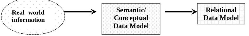
Once conceptual data model is completed, it needs to be transformed into a logical data model. Data model transformation is shown in Figure 1-3.
Figure 1-3 Data model transformation flow.
Real -world information
Semantic/ Conceptual Data Model
Relational Data Model
Real -world information
Semantic/ Conceptual Data Model
Relational Data Model
Requirements
Definition LOGICAL DESIGN
PHYSICAL DESIGN
Object-based Data Model
OR
1.1.2 Mapping conceptual design to logical design using relational data model
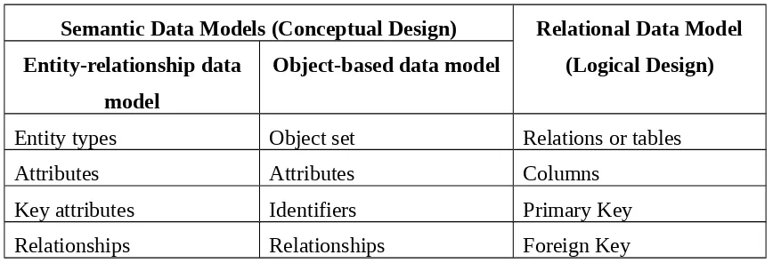
The result of transformation from conceptual design to logical design can be summarized in the following table :
Table 1-1: Mapping conceptual design to logical design
Semantic Data Models (Conceptual Design) Relational Data Model (Logical Design) Entity-relationship data
model
Object-based data model
Entity types Object set Relations or tables
Attributes Attributes Columns
Key attributes Identifiers Primary Key
The following exercise requires the students to apply and demonstrate their understandings in designing a relational database application. Based on the system requirements provided, students should be able to develop conceptual data model (using ERD) and logical data model (using Relational notation). At the end of the process, they need to implement the data model using a relational DBMS.
1.2
Exercise
1.2.1 Conceptual/Semantic Data Model for Banking Enterprise
Consider that a bank keeps track of customers, employees, accounts and bank’s loan. Develop a Chen ERD (Entity relationship diagram) based on these requirements: (Note: Refine the ERD if necessary).
The bank is organized into branches. Each branch is located in a particular city and is identified by a unique name. The bank monitors the assets of each branch. A branch can originate one or more loans.
Bank customers are identified by their customer-id values. The bank stores customer’s name, street and city where the customer lives. Customer may have accounts and can take out loans. A customer may be advised by a particular banker/employee, who may act as loan officer or personal banker for that customer, and that particular banker can advise one or more customers.
The bank maintains information about accounts. Accounts can be held by more than one customer, and a customer can have more than one account. Each account is assigned with a unique account number. The bank maintains a record of each account’s balance, and the most recent date on which the account was accessed by each customer holding the account.
A loan originates at a particular branch and can be held by one or more customers. A loan is identified by a unique loan number. For each loan, the bank keeps track of the loan amount. Each loan is associated with one or more
payments. A payment number identifies a particular payment for a specific loan. The date and amount are recorded for each payment.
1.2.2 Logical Database Design for Banking Enterprise
Convert Banking Enterprise ERD into a logical design. Use Relational notation for this purpose.
1.2.3 Physical Database Design and implementation for Banking Enterprise
1.3
Self Review Questions
1. What do you understand about relational data model?
2. There are two methods to design a relational data model. Define both methods.
3. What are the basic components of ERD?
4. How mapping from conceptual design to logical design can be performed?
2
Introduction
Object-based data model is a generic data model, which is applicable to all types of information content. It is one of the approaches that can be used in order to develop a conceptual data model for any database application. In fact, there are some variations in the notations for object-based data model. However, in this practical, students will use the notations, which are suggested in the textbook (ROB, P AND CORONEL, C., 2004. Database Systems : Design, Implementation & Management). Although the notation is simple and straightforward, it covers all the essential parts of object-based modeling techniques. At this stage, the intention is to introduce the basic concept of object-based data modeling and to show how object-oriented concepts have influenced data model.
The objectives of this practical include:
To describe the essentials of the object-based modelling method To develop conceptual design using Object-based approach To define business rules for relationship between objects To identify participation constraints in relationship To identify superclass/subclass for objects
2.1
Theoretical Background
Students will be given the opportunity to learn how to develop database conceptual design using UML (Unified Modeling Language) in subsequent chapters. UML has been accepted as a standard to graphically model a system and it has been widely used for object-oriented system design.
Students are required to develop a conceptual design using object-based approach. There are a few assumptions that students need to know before attempting to develop object-based data model. These include:
i. All database requirements for the system has been collected. ii. Conceptual design for the system was initially has been developed
using ER approach.
iii. Conceptual design has been mapped to relational data model(logical design).
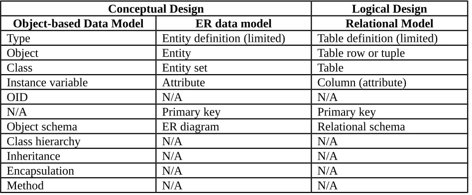
Table 2-1 below presents a comprehensive comparison of features between three types of data models.
Table 2-1 : A Comparison of Object-based data model, ER data model, and Relational Model Features
Conceptual Design Logical Design
Object-based Data Model ER data model Relational Model
Type Entity definition (limited) Table definition (limited)
Object Entity Table row or tuple
Class Entity set Table
Instance variable Attribute Column (attribute)
OID N/A N/A
N/A Primary key Primary key
Object schema ER diagram Relational schema
Class hierarchy N/A N/A
Inheritance N/A N/A
Encapsulation N/A N/A
2.2
Exercise
2.2.1 Converting relational database tables to the equivalent object-based data model.
Based on information on Figure 2-1 below, design an object-based conceptual model for Insurance Management Database. Please refer to assumptions made in section 2.1.
Table Name : POLICY_HOLDER
Table Name : AGENT
Table Name : INSURANCE
2.2.2 Define business rules for the relationships with objects
Based on the conceptual model generated in exercise 2.2.1, specify business rules for the relationships between objects.
2.2.3 Identify participation constraints in relationship between objects
Specify participation constraints for the relationships defined inexercise 2.2.2
2.2.4 Develop object space diagram representing object’s state for some instances
Based on the data populated in the tables (refer Figure 2-1) draw an object space diagram for Insurance Management database that represents the object’s state for instances of Policy Holder with PH_ID = 1001,1002 and 1004. Please use appropriate OIDs and attributes names for all objects.
2.2.5 Define a superclass for object
A superclass has been defined for Policy_Holder class. Please select one Policy_Holder instance that become the subclass of the superclass. Draw an object space diagram to illustrate this additional information. Information about the superclass is provided as follows:
Superclass name : PERSON
OID : P1V01
2.3
Self Review Questions
1. Mapping of object-based data model to relational model involves
transformation of some features. List the features before transformation and after transformation.
2. List and describe briefly five attributes of object-based data model.
3. What do you understand about object space diagram? How it differs from object-based data model?
4. Explain the concept of inheritance. How many types of inheritance available? Give example for each.
3
Introduction
Enhanced Entity Relationship Diagram is a conceptual data modeling technique that actually adds some object-oriented concepts in ERD. These additional concepts include subclasses/superclasses, specialization/generalization, categories and attribute inheritance.
It is important for students to understand that EERD includes all modeling concepts of basic ERD but it does not attempt to cover all object concepts. In order to develop EERD it is crucial to know which notations to be adopted. In this practical, Chen notation will be used in all parts. Students will have the opportunity to develop EERD using UML notations in Chapter 4.
The objectives of this practical include:
To identify the essential objects components added in EERD To define constraints on specialization /generalization
To Illustrate specialization /generalization constraints in both, EERD and UML
3.1
Theoretical Background
3.1.1 Constraints and characteristics of specialization and generalization
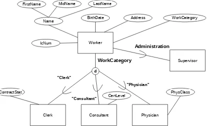
In fact, more than one specialization can be defined on the same entity type (superclass) as shown in Figure 3-1. In this case, entities may belong to each of subclass. Nevertheless, a specialization may also involve only a single subclass such {Supervisor} subclass in the figure. No circle notation is required for this type of specialization.
Worker
Clerk Consultant Physician
FirstName MidName LastName
Name BirthDate Address WorkCategory
ContractStat
CertLevel PhysClass
d
WorkCategory
"Clerk"
"Consultant"
"Physician"
IcNum
Supervisor Administration
There are a few types of constraints that determine specialization /generalization of entities. These include:
a. Constraints based on attribute of superclass
If all subclasses in a specialization are defined based on the same attribute of superclass, the specialization itself is called attribute-defined specialization. The attribute that involves in the specialization is called defining attribute. In EERD, the defining attribute name is placed next to the line from the circle to the superclass. Figure 3-1 shows an example of a defining attribute called WorkCategory.
b. Constraints based on value of attribute of superclass
In other case, specialization may also be based on the value of some attribute of the superclass. In other words, the entities that will become the member of each superclass are determined by placing a condition on the value of attributes of the superclass. The subclasses generated as the result of this type of specialization is called predicate-defined or conditioned-defined subclasses.
The value of attribute which involves in the specialization is called defining predicate. In EERD, the defining predicate name is placed next to the line that connects the subclass to the specialization circle.
c. Constraints based on user
This is the case where there is no condition applied in order to determine membership in a subclass. Subclass membership is based on database users when they apply the operation to add an entity to the subclass. No direct representation of this type of constraint in EERD.
d. Constraints based on disjointness aspect
This type of constraint specifies whether an entity can be a member of more than one subclass of the specialization or not.
e. Constraints based on completeness aspect
This type of constraint determines whether an entity has the option for not to belong to any of the subclasses or not.
Since there are various notations to model Disjointness and Completeness constraints, therefore there are many ways can be adopted in order to represent/design generalization and specialization for these types of constraints.
In context of Chen notation, there are 2 categories of constraints : 1) Disjointness
i. Disjoint : is represented by d symbol (Entity can be a member of at most one of the subclasses)
ii. Joint (Overlapped) : is represented by o symbol.
(Entity may be a member of more than one subclass) 2) Completeness
i. Total: is represented by double line (An entity must be a member of subclass)
Therefore, there are 4 types of combination between both constraints :
i. Disjoint,total
ii. Disjoint,partial
iii. Overlapped,total
iv. Overlapped,partial
In context of UML notation there are 3 categories of constraints : 1) Disjointness (the meaning is similar with Chen notation)
i. Disjoint
ii. Overlapped
2) Completeness
i. Complete: represents the END of hierarchy tree
ii. Incomplete: represents inheritance may be extended
3) Participation (the meaning is similar with Chen notation : Total/Partial)
i. Mandatory
ii. Optional
Constraints in UML are placed inside the curly brackets { }.Combination between (1 and 2) or (3 and 1) can be selected.
The results of combinations: If (1 and 2):
i. {disjoint, complete}
ii. {disjoint}
iii. {overlapped, complete}
iv. {overlapped}
If (1 and 3) :
i. {mandatory, disjoint}
ii. {mandatory, overlapped}
iii. {optional, disjoint}
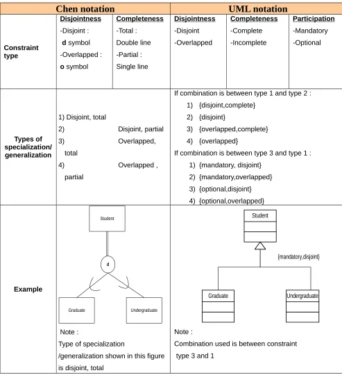
Comparison between Chen and UML notation to represent specialization/generalization constraints can be summarized in Table 3-1.
Table 3-1 : Specialization/generalization constraints
Chen notation
UML notation
Constraint type
Disjointness
-Disjoint :
d symbol -Overlapped :
o symbol
Completeness -Total : Double line -Partial : Single line Disjointness -Disjoint -Overlapped Completeness -Complete -Incomplete Participation -Mandatory -Optional Types of specialization/ generalization
1) Disjoint, total
2) Disjoint, partial 3) Overlapped,
total
4) Overlapped , partial
If combination is between type 1 and type 2 : 1) {disjoint,complete}
2) {disjoint}
3) {overlapped,complete} 4) {overlapped}
If combination is between type 3 and type 1 : 1) {mandatory, disjoint}
2) {mandatory,overlapped} 3) {optional,disjoint} 4) {optional,overlapped} Example Student Graduate Undergraduate d Note :
Type of specialization
/generalization shown in this figure is disjoint, total
Student
Graduate Undergraduate {mandatory,disjoint}
Note :
Combination used is between constraint type 3 and 1
3.2.1 Drawing Enhanced Entity Relationship (EER) data model
Design a database using EER diagram to keep track information of a transportation database. Show all related specialization and generalization constraints using Chen notation. You can use Microsoft Visio software for this purpose. Assume that the following requirements were collected:
Each vehicle has a vehicle number and it is of a particular vehicle type. The vehicle is kept in particular parking lot.
Each vehicle type has a vehicle class, a description and a maximum load.
Each parking lot has a lot number and a venue.
The database also keeps track of the investor of each vehicle and the workers who have maintained the vehicle type.
Each worker works on one or many vehicle service.
Each vehicle undergoes service many times; hence, it is related to a number of service records.
A service record includes as attributes the date of maintenance, the number of hours spent on the work, and the type of service done.
We use a weak entity type to represent vehicle service, because the vehicle number is used to identify a service record.
An investor is either an individual or a company. Hence, we use a union category that is a subset of the union of company and individual entity types.
Both driver and workers are subclasses of INDIVIDUAL.
Each driver has specific attributes license id, license expiry date and tenure.
Each worker has specific attributes wages and working slot.
All individual entities in the database have data kept on their IC number, name, and address and telephone number.
For company entities, the data kept includes name, address and telephone number.
3.3
Self Review Questions
1. What do you understand about EERD?
2. There are various types of constraints that determine specialization
/generalization of entities in inheritance. Give example of constraints based on value of attribute of superclass.
3. There are some differences to determine completeness constraints between Chen notation and UML. Define the differences.
4. Convert the following EERD to its equivalent UML notation.
Personel
Worker Student
4
Introduction
UML (Unified Modeling Language) is one of object modeling methodologies. UML is closely related with object-oriented concepts and it is regarded as a language that consists of a set of symbols and diagrams that form a model of a system. The primary attention of UML is actually for software design. However, since the major part of software design involves designing databases that will be accessed by the software modules, UML contributes in initial phase of database design process. UML is actually an alternative in database design notation.
The objectives of this practical include:
To apply object modelling techniques using UML class diagram in designing database conceptual model
To map an EERD (Chen notation) to its equivalent UML class diagram representation
4.1
Theoretical Background
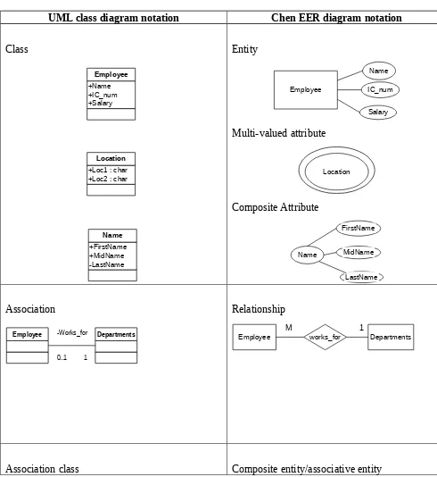
There are different types of diagrams in UML. Nevertheless keep in mind that the most relevant is Class diagram, which is similar to EER diagram in many ways except in terminology. Table 4-1 consists of the components of UML class diagram which represent EER diagram notation/terminology.
Table 4-1 : UML and Chen notation
UML class diagram notation Chen EER diagram notation
Class +Name +IC_num +Salary Employee
+Loc1 : char +Loc2 : char
Location +FirstName +MidName -LastName Name Entity Employee IC_num Salary Name Multi-valued attribute Location Composite Attribute Name FirstName LastName MidName Association
Employee -Works_for Departments
0..1 1
Relationship
Employee works_for Departments
Student Class Enroll 1 -enrolls_in 1 -consists_of
Student Enroll Class
M N
M: N is decomposed into :
Student 1 M Enroll M 1 Class
Composition
Employee -Has Dependant
1 0..*
* Represents strong, identifying relationship
Aggregation
Team -Consists of Player
0..1 0..*
* Represents weak relationship
Relationship strength (child-parent)
Employee 1 Has M Dependant
(1,1) (0,M)
(Deleting Employee means deleting Dependant) * ON DELETE CASCADE
Team 1 consistsOf M Players
(0,1) (0,M)
(Deleting Team does not deleting Players) * ON DELETE SET NULL
Class generalization Employee Accountant Mechanic Pilot {optional,disjoint} Generalization/specialization Mechanic Accountant Pilot Employee d Class generalization
(Note: EERD Category/Union types need to be
represented in its generalization form before it can be used in UML notation)
{disjoint,mandatory}
Property
Building Lot
U
Building Lot
Property
Total category PROPERTY and its similar generalization:
d
Building Lot
Property
Operations/methods Not applicable
Visibility Not applicable
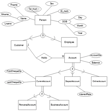
Exercise in this chapter requires the students to develop a UML class diagram based on a given Chen EER diagram. Rational Rose Professional Data Modeler by IBM is one of the tools used to construct UML diagrams. However, in the following exercise students will use Microsoft Visio software (UML Static Structure) to draw the diagram.
Based on Chen EER diagram below, draw its equivalent representation of UML class diagram using Visio Professional software. Show all constraints and association clearly.
Person
Customer
Employee
Account
CurrentAccount DepositAccount OnlineAccount
[image:31.595.100.521.170.602.2]PersonalAccount BusinessAccount O Holds d d Sex IC_num DOB Day Month Year Name Fname Lname Mname 1 M AccountNo Balance InterestRate FirstChequeNo LastChequeNo Tel_Num
Figure 4-1 : EER diagram for Bank application
4.3
Self Review Questions
2. What is the type of UML diagram is the most relevant for database design?
3. Is there any specific notation for union types in UML ?
4. How union types in EER diagram is represented in UML notation?
5.1 Objectives
5
Introduction
Once conceptual design is completed, the conceptual model is mapped into a logical model during logical database design phase. Since there are various types of data model can be used in conceptual design, designer needs to choose one data model in order to transform it to its equivalent logical representation.
Keep in mind that, logical model is dependent of the type of target DBMS to be implemented, therefore one need to ensure that the type of logical model developed matches with the type of DBMS. Therefore if the type of DBMS is Relational DBMS (RDBMS), a relational data model needs to be developed. In this practical, since the target DBMS is an Object-relational DBMS (ORDBMS) specifically Oracle 9i, an object-relational data model will be developed. It is assumed that students are familiar with mapping conceptual model to a relational data model.
The objectives of this practical include:
To differentiate the terminology and notation of UML class diagram with SQL3 and Oracle 9i.
To develop object-relational notation which are equivalent to UML class diagram notation
To identify the strategies for representing a class inheritance tree in Object-relational data model based on UML class diagram
To map association and composition in UML class diagram into its
5.1
Theoretical Background
It is clear that ORDBMS consists of some object-relational concepts. Therefore it is best to use EERD or UML class diagram in order to develop an object-relational data model since both diagrams covers a lot of object-relational features.
However, it is not wrong to use other models like ERD or object-based data model for the same purpose. In this practical, UML class diagram will be used since it allow us to translate more of the real-world structure into the database schema. Students will learn how to transform it into an object-relational data model based on some rules and guidelines for model/schema transformation originated from relational data model transformation rules.
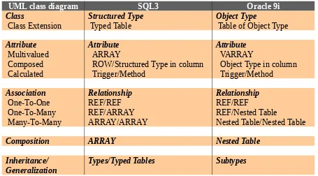
[image:34.595.86.541.453.705.2]Table 5-1 consists of rules as guidelines for schema transformation from conceptual design using UML terminology to object-relational design using SQL3 (a generic database language) and Oracle9i (a specific DBMS) terminology.
Table 5-1 : Schema transformation terminology
UML class diagram SQL3 Oracle 9i
Class
Class Extension Structured Type Typed Table Object Type Table of Object Type Attribute Multivalued Composed Calculated Attribute ARRAY
ROW/Structured Type in column Trigger/Method
Attribute VARRAY
Object Type in column Trigger/Method Association One-To-One One-To-Many Many-To-Many Relationship REF/REF REF/ARRAY ARRAY/ARRAY Relationship REF/REF REF/Nested Table
Nested Table/Nested Table
Composition ARRAY Nested Table
Inheritance/ Generalization
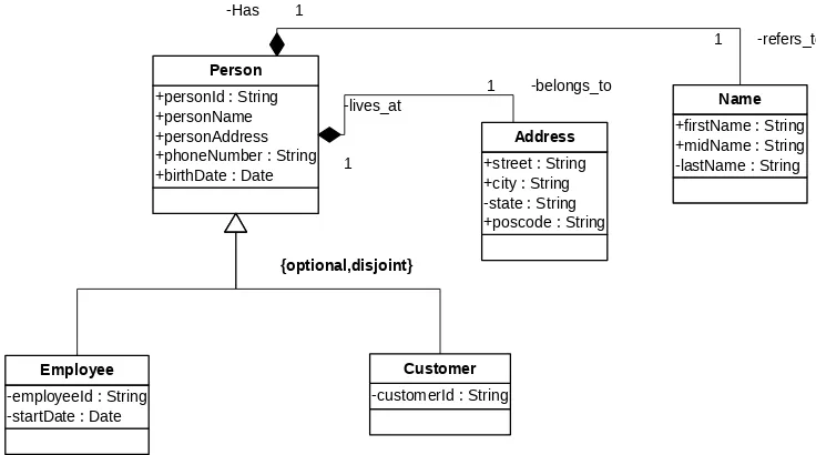
Section 5.2 (Step-by-step) shows how mapping of a UML class diagram to an object-relational data model using Oracle9i terminology is performed. Assume that a complete UML class diagram is the one shown in Figure 5-1.
+personId : String +personName : Name +personAddress : Address +phoneNumber : String +birthDate : Date
Person
+firstName : String +midName : String -lastName : String
Name
+street : String +city : String -state : String +poscode : String
Address -Has 1 -refers_to 1 -lives_at 1 -belongs_to 1
-employeeId : String -startDate : Date
Employee
-customerId : String Customer
-DependantId : String -DependantName : Name -DependantAddress : Address
Dependant -Has 1 -isDependantOf * -isAdvisedBy 1 -seekAdviseFrom 0..* {optional,disjoint} -Has 1 -refersTo 1 -livesAt 1 -belongsTo 1
5.2
Step-by-step
Students may follow the steps outlined below before attempting to make schema transformation. These are general steps for conceptual schema transformation :
Step 1: Mapping class inheritance tree and abstract class
Oracle 9i allows specialization of an object type by creating subtypes. Subtypes can be created by deriving them from a parent object type(supertype). Subtypes and supertypes are related by inheritance. Since subtypes are specialized versions of their parent, subtypes have all the parent's attributes and methods plus any specializations that are defined in the subtype itself. Subtypes and supertypes connected by inheritance make up a type hierarchy.
Figure 5-2 shows an example of class inheritance tree in UML class diagram where there is one superclass Person and two subclasses (Employee and customer). Address and Name are actually abstract class that represents user-defined types. In O-R approach, the main classes in UML class diagram become object types. Therefore we would expect that class Person, Employee and Customer in Figure 5-2 will all be transformed into object types.
+personId : String +personName +personAddress +phoneNumber : String +birthDate : Date
Person
-employeeId : String -startDate : Date
Employee
-customerId : String
Customer {optional,disjoint}
+firstName : String +midName : String -lastName : String
Name
+street : String +city : String -state : String +poscode : String
[image:36.595.99.467.505.710.2]Address -Has 1 -refers_to 1 -lives_at 1 -belongs_to 1
The example of Object-relational design of these object types based on Oracle 9i syntax is illustrated by the following figures :
Type NAME_OBJTYP
firstName midName lastName
VARCHAR2(15) VARCHAR2(15) VARCHAR2(15)
Figure 5-3: Object relational representation of the NAME_OBJTYP
Type ADDRESS_OBJTYP
street city state poscode
VARCHAR2(15) VARCHAR2(10) VARCHAR2(10) NUMBER
Figure 5-4: Object relational representation of the ADDRESS_OBJTYP
Type PERSON_OBJTYP
personId(PK) personName personAddress phoneNumber birthDate VARCHAR2(10) NAME_OBJTYP ADDRESS_OBJTYP VARCHAR2(9) DATE
Figure 5-5: Object relational representation of the PERSON_OBJTYP
Type EMPLOYEE_OBJTYP under PERSON_OBJTYP
EmployeeId (PK) startDate
VARCHAR2(10) DATE
Figure 5-6: Object relational representation of the EMPLOYEE_OBJTYP
Type CUSTOMER_OBJTYP under PERSON_OBJTYP
CustomerId (PK) VARCHAR2(10)
Step 2: Mapping class association
Next, relationship or in UML terminology is called association can be mapped into O-R model by selecting one REF attribute that establishes connection between objects.
Figure 5-1 shows two classes that are involved in association. These classes are Employee and Customer. REF attribute is actually a foreign key in relational data model terms. Since object types for Customer (Customer_ObjTyp) has been created before, some modification need to be made on its logical design in order to add REF attribute. The result of the transformation is shown in Figure 5-8.
Type CUSTOMER_OBJTYP under PERSON_OBJTYP
CustomerId (PK) emp_ref (FK) VARCHAR2(10) EMPLOYEE_OBJTYP
Figure 5-8: Object relational representation of the CUSTOMER_OBJTYP
Step 3: Mapping class composition
Relationship strength or specifically in UML terminology is called composition can be transformed into an O-R model by transforming the child/dependent object into a nested table. Before this transformation is possible, the child object need to be first mapped into an object type. For example, child object in Figure 5-1 is Dependant, which is related to its parent object, Employee. The result of transformation is shown in
Type DEPENDANT_OBJTYP
DependantId (PK) dependantName dependantAddress VARCHAR2(10) NAME_OBJTYP ADDRESS_OBJTYP
Figure 5-9: Object relational representation of the DEPENDANT_OBJTYP
Column dependantList
(of DEPENDANT_NESTEDTAB (as table of DEPENDANT_OBJTYP))
DependantId (PK) dependantName dependantAddress VARCHAR2(10) NAME_OBJTYP ADDRESS_OBJTYP
Figure 5-10: Object relational representation of the Nested Table dependantList
Beside that, logical design for Employee_ObjTyp (Figure 5-6) need to be modified in order to add an attribute that reflects composition of Dependant nested table. The new representation of O-R model for Employee_ObjTyp is illustrated in Figure 5-11.
Type EMPLOYEE_OBJTYP under PERSON_OBJTYP
EmployeeId (PK) startDate dependantList
VARCHAR2(10) DATE DEPENDANT_NESTEDTAB
Step 4: Creating Object Tables
O-R data model is never complete without creating tables. Creating object types alone will only defines logical template/structure, but not its storage specification. In order to use these objects types, they need to be associated in object tables as column object or used to construct the whole structure of object table.
For example ADDRESS_OBJTYP and NAME_OBJTYP are used as column objects in Person table (PERSON_OBJTAB). Person table is created based on object type PERSON_OBJTYP.
Figure 5-12 shows Object relational representation of the PERSON_OBJTAB.
Table PERSON_OBJTAB (of PERSON_OBJTYP)
PersonId (PK)
personName personAddress phoneNumber birthDate
VARCHAR2(10) NAME_OBJTYP ADDRESS_OBJTYP VARCHAR2(9) DATE
Figure 5-12: Object relational representation of the PERSON_OBJTAB
Other object tables that need to be created are Employee and Customer object table.
Note:
1) Not all object types are used to define object table. User-defined type like address and name are usually used as column objects.
5.3
Exercise
Based on UML class diagram for a purchase order application below, create an object-relational data model using Oracle 9i platform.
Guideline:
a) Name and Address are defined as column objects
b) Phonelist is defined as varray type
c) Order details is defined as nested table
d) Other classes are defined as object types and only some of these types are extended to tables
+personId : String +personName : Name +personAddress : Address +phoneNumber : PhoneList +birthDate : Date
Person
+firstName : String +midName : String -lastName : String
Name
+street : String +city : String -state : String +poscode : String
Address -Has 1 -refers_to 1 -lives_at 1 -belongs_to 1
-employeeId : String -startDate : Date -title : String
Employee
-customerId : String -companyName : String
Customer {optional,disjoint}
-orderId : String -orderDate : Date -requiredDate : Date -shippedDate : Date -shipAddress : Address
Orders
-orderId : String -productId : String -unitPrice : Currency -discount : int
OrderDetails
-shipperId : String -companyName : String -phoneNumber : PhoneList
Shippers
-phoneNumber : String
PhoneList
-productId : String -productName : String -unitPrice : Currency -quantityPerUnit : int
[image:41.595.86.546.270.702.2]Product -Has 1 -belongsTo 1..* -Has 1 -belongsTo 1..* -Has 1 -Refers_to * -Refers_to 1 -Has * -places 0..1 -is_made_by * -Receives 0..1 -is_received_by * -is_shipped_by * -ships_order 0..1
5.4
Self Review Questions
1. What is the output of logical design phase?
2. How UML class diagram terminology differs from SQL3 and Oracle 9i in terms of class and relationship?
3. Do you agree that all object types need to be extended to object tables? Give your reasons.
4. What type of class that is usually mapped into nested table?
6
Introduction
SQL3, which also referred as SQL: 1999 is an extension of SQL92 standard (SQL92). The purpose of the extensions is fulfilling the needs of incorporating some of object-oriented features in developing database applications. These are the features in SQL3 that introduce object-oriented structure in its superset, SQL92:
1. User-defined types (ADTs, row types) 2. User-defined functions and procedures
3. Type constructors for collection types (sets, lists, and multisets) 4. Type constructors for row types and reference types
5. Support for large objects (BLOBs and CLOBs)
The objectives of this practical include :
To map object-relational data model on physical design
6.1
Theoretical Background
[image:44.595.129.556.341.514.2]This practical will concentrate only on the first feature of SQL3, user-defined types (UDT). This feature enable user to define customized data type in addition to the normal built-in types defined by SQL. Objects in SQL3 can be classified based on the categories of user-defined types where they are defined. Basically, user-defined types in SQL3 can be divided into two main categories namely Row types and ADT (Abstract data type) or sometimes referred as column types. ADT can be further divided into two other categories called distinct and structured types. The classification of user-defined types of SQL3 is illustrated in Figure 6-1.
Figure 6-1: User-defined types classification in SQL3
6.1.1 Row Type
A row type is a sequence of field name/data type pairs that represent a table definition.
The row type provides a data type that can represent the types of rows in tables, so that complete rows can be stored in variables, passed as arguments to routines, and returned as return values from function invocations.
USER-DEFINED TYPES (UDT)
ROW TYPE ABSTRACT DATA TYPE(ADT)/COLUMN TYPE
Row type can have references to objects of row types (reference type) and it also can be used as column types/ADT.
Below are SQL3 DDL statements for definition of row types and tables as the results of mapping object-relational data model (logical design) to its equivalent schema definition (physical design).
Row Type SYSTEM_TYP
SName (PK) minAge
String Integer
CREATE ROW TYPE system_typ (sname string,
[image:45.595.80.526.225.743.2]minAge integer) ;
Table SYSTEM_TAB (of SYSTEM_TYP)
sName minAge
String Integer
PK
CREATE TABLE system_tab of system_typ;
Row Type SERIES_TYP
SrsName (PK) theme inSys
String Integer Reference
system_typ
CREATE ROW TYPE series_typ (srsname string,
theme string,
[image:45.595.76.532.677.724.2]inSys ref(system_typ));
Table SERIES_TYP (of SERIES _TYP)
SrsName (PK) theme inSys
String Integer Reference
6.1.2 Column type/Abstract Data Type
A user-defined abstract data type (ADT) definition encapsulates attributes and operations in a single entity.
Abstract data type (ADT) is defined by specifying :
Attributes that represent the value of the ADT
Operations that define the equality and ordering relationships of the ADT.
Operations that define the behavior (and any virtual attributes) of the ADT. (Note that this practical only covers attributes definition in ADT. )
Instances of ADTs can be persistently stored in the database only by storing them in columns of tables.
ADT is subdivided into distinct type and structured types. Distinct type provides mechanism to customize the name of built-in data type with a more meaningful user-defined data type name. It is a simpler type of ADT because no attributes need to be defined during the declaration.
Example:
CREATE DISTINCT TYPE studentIdTyp AS VARCHAR(5); CREATE DISTINCT TYPE weightTyp AS DECIMAL(5,2); CREATE DISTINCT TYPE hireDateTyp AS DATE;
While, structured type consists of one or more definitions of attribute or methods.
Example:
CREATE TYPE contactInfoTyp AS( TelNo VARCHAR(9),
These ADT need to be defined as part of table structure so that data can be persistently stored.
Example:
CREATE TABLE student( StudentId studentIdType, Name VARCHAR(30),
Contact contactInfoTyp);
SQL 3 allows UDTs to be defined as subtypes of other UDTs. A subtype inherits the structure and behavior of its supertypes. Supertype need to be defined prior to subtypes definition. The clause NOT FINAL enables creation of subtypes from a particular types. By default, types are created as FINAL which means that the type cannot be further specialized.
Example:
CREATE TYPE personTyp AS( Name VARCHAR(30),
Contact contactInfoTyp) NOT FINAL;
CREATE TYPE studentTyp UNDER personTyp AS( StudentId studentIdType)
NOT FINAL;
SQL 3 also offers subtable facility. A table can be declared as a subtable of one or more supertables (it is then a direct subtable of these supertables), using an UNDER clause associated with the table definition. When a subtable is defined, the subtable inherits every column from its supertables, and may also define columns of its own. The subtable facility is completely independent from the UDT subtype facility.
Example:
CREATE TABLE student of studentTyp (REF IS studentId SYSTEM GENERATED, PRIMARY KEY (studentId));
Below are some SQL3 DDL statements for definition of column types and tables as the results of mapping object-relational data model (logical design) to its equivalent schema definition (physical design). The example is based on object-relational data model in Chapter 5.
Column Type NAME_TYP
firstName midName lastName
String String String
CREATE TYPE Name_Typ AS( firstName string(20), midName string(20), lastName string(20));
Column Type ADDRESS_TYP
Street city state poscode
String String String Number
CREATE TYPE Address_Typ AS( street string(15),
city string(10), state string(10) poscode integer);
Row Type PERSON_TYP PersonId
(PK)
personName personAddress phoneNumber birthDate
String Object
Type Object Type String Date
CREATE ROW TYPE person_typ (personId string,
personName name_typ,
personAddress address_typ, phoneNumber string
Table PERSON_TAB (of PERSON_TYP) PersonId
(PK) personName personAddress phoneNumber birthDate
String Object Type Object Type String Date
VARCHAR2(10) NAME_OBJTYP ADDRESS_OBJTYP VARCHAR2(9) DATE
6.2
Exercise
6.3
Self Review Questions
1. List object-oriented features of SQL3.
2. Describe user-defined classification in SQL3.
3. What is the difference between row types and ADT (Abstract data type)?
4. Can column types be used as row types?
7
Introduction
In Oracle 9i, object types represents row types and column types, in which SQL3 makes some distinction for both types. However, the scope of object types usage will determine whether it is a row object or column object. If object type appears in the whole sequence of object table, it is called as row objects, but if it only occupy some columns of other object table, it is called column object.
[image:52.595.82.511.54.322.2]Types in Oracle 9i can be divided into several parts as shown in Figure 7-1.
Figure 7-1: Oracle 9i Type classification The objectives of this practical include:
To map object-relational data model on physical design
To write DDL statement using Oracle 9i syntax based on object relational schema
ORACLE 9i TYPES
OBJECT
TYPES REF TYPES COLLECTION TYPES
ARRAY
TYPES NESTEDTABLE
7.1
Theoretical Background
Here are some examples of Oracle 9i types DDL statement, which are mapped from object-relational data model.
7.1.1 Object type as column type
Type NAME_OBJTYP
firstName midName lastName
VARCHAR2(15) VARCHAR2(15) VARCHAR2(15)
CREATE TYPE name_objtyp AS OBJECT( firstName VARCHAR2(15),
midName VARCHAR2(15), lastName VARCHAR2(15)); /
Type ADDRESS_OBJTYP
street City state poscode
VARCHAR2(15) VARCHAR2(10) VARCHAR2(10) NUMBER
CREATE TYPE address_objtyp AS OBJECT( street VARCHAR2(15),
city VARCHAR2(10), state VARCHAR2(10), poscode number);
7.1.2 Object type as row type
Type CUSTOMER_OBJTYP
custNo custName CustAdd
ress
VARCHAR2(15) Name_objtyp Address
_objtyp CREATE TYPE customer_objtyp AS OBJECT(
CustNo VARCHAR2(15), CustName name_objtyp,
CustAddress address_objtyp);
/
CREATE TABLE customer_tab of customer_objtyp
(CustNo PRIMARY KEY) OBJECT IDENTIFIER PRIMARY KEY; /
7.1.3 Collection types - Array type
Type PHONELIST_VARTYP PhoneNum
Maximum 5 values VARCHAR2(15)
CREATE TYPE phonelist_vartyp AS VARRAY (5) OF VARCHAR2(20); /
Modification needs to be made for CUSTOMER_OBJTYPto include the new array type.
Type CUSTOMER_OBJTYP
custNo custName CustAddress custContact
VARCHAR2(15) Name_objtyp Address_objtyp Phonelist_vartyp
CREATE TYPE customer_objtyp AS OBJECT( CustNo VARCHAR2(15),
CustName name_objtyp,
CustAddress address_objtyp, CustContact Phonelist_vartyp); /
CREATE TABLE customer_tab of customer_objtyp
Inserting values into customer_tab
Example :
INSERT INTO customer_tab VALUES(‘C001’, name_objtyp(‘Mohd’,’Azmi’,’Ali’),
address_objtyp(‘Jln Merbau’,’Ayer Keroh’,’Melaka’,75450), Phonelist_vartyp(‘012-8792345’,’06-5645345’));
7.1.4 Collection types – Nested table
Type DEPENDANT_OBJTYP
DependantId (PK) dependantName dependantAddress
String Object Type Object Type
VARCHAR2(10) NAME_OBJTYP ADDRESS_OBJTYP
CREATE TYPE dependant_objtyp AS OBJECT ( dependantId VARCHAR2(10),
dependantName name_objtyp,
dependantAddress address_objtyp); /
Column dependantList
(of DEPENDANT_NESTEDTAB (as table of DEPENDANT_OBJTYP))
dependantId dependantName dependantAddress
VARCHAR2(10) NAME_OBJTYP ADDRESS_OBJTYP
CREATE TYPE dependant_nestedtab AS TABLE OF dependant_objtyp; /
Type EMPLOYEE_OBJTYP
EmployeeId (PK) startDate dependantList
String Date Nested Table
VARCHAR2(10) DATE DEPENDANT_NESTEDTAB
CREATE TYPE employee_objtyp AS OBJECT( EmployeeId VARCHAR2(10),
StartDate DATE,
Then, create object table based on object type created for employee. CREATE TABLE employee_tab of employee_objtyp (EmployeeId PRIMARY KEY)
OBJECT IDENTIFIER PRIMARY KEY
NESTED TABLE DependantList STORE AS DependantListStorageTable ((PRIMARY KEY (NESTED_TABLE_ID,dependantId)))
; /
OR
CREATE TABLE employee_tab of employee_objtyp( PRIMARY KEY (EmployeeId))
OBJECT IDENTIFIER is PRIMARY KEY
NESTED TABLE DependantList STORE AS DependantListStorageTable ((PRIMARY KEY (NESTED_TABLE_ID, dependantId)))
; /
Inserting values into employee_tab
INSERT INTO employee_tab VALUES
('E001',SYSDATE,DEPENDANT_NESTEDTAB()); /
The values for nested table in the DependantList column need to be inserted.
INSERT INTO TABLE( SELECT e.dependantList FROM employee_tab e
WHERE e.employeeId = ’E001’) VALUES (‘D101’,
name_objtyp(‘Nur’,’Ainun’,’Anas’),
7.1.5 REF type
REF type is used to show association/relationship between objects.
Type SYSTEM_OBJTYP
SName (PK) minAge
VARCHAR2(15) INTEGER
CREATE TYPE system_objtyp AS OBJECT (sname VARCHAR2(15),
minAge INTEGER) ;
Then, create an object table for System.
CREATE TABLE system_tab OF system_objtyp (sname PRIMARY KEY)
OBJECT IDENTIFIER PRIMARY KEY; /
Type SERIES_OBJTYP
SrsName (PK) theme inSys
VARCHAR2(15) INTEGER system_objtyp
CREATE TYPE series_objtyp AS OBJECT (srsname VARCHAR2(15),
theme INTEGER,
inSys REF system_objtyp );
Then, create an object table for Series.
CREATE TABLE series_tab OF series_objtyp( PRIMARY KEY (srsname),
Inserting values into system_tab
Values for values need to be inserted prior to insertion of child table.
INSERT INTO system_tab VALUES(‘UNIX’,4);
Then, insert values for child table.
INSERT INTO series_tab SELECT ‘VS400’,1200,REF(s) FROM system_tab s
WHERE s.sname=’UNIX’;
OR
INSERT INTO series_tab VALUES
(‘VS400’,1200, (SELECT REF(s) FROM system_tab s WHERE s.sname=’UNIX’));
SCOPE FOR constraint on a REF is not allowed in CREATE TABLE statement. Therefore, to ensure that inSys attribute in series_tab table can reference only object table system_tab, issue the following ALTER TABLE statement on series_tab table.
7.1.6 Type inheritance
Oracle 9i allows type inheritance as what is provided by SQL3. With this facility, a subtype can be created under a base type only if the base type allows subtypes. This is based on FINAL property of type. By default, all new types are created as FINAL. FINAL clause indicates that particular type is the last of the series and cannot have subtypes defined under it. To enable subtype creation, one must specify NOT FINAL clause in CREATE TYPE statement.
Example :
CREATE TYPE person_ObjTyp AS OBJECT( Name VARCHAR2(30),
Contact VARCHAR2(9)) NOT FINAL;
CREATE TYPE student_ObjTyp UNDER person_ObjTyp( StudentId VARCHAR2(30))
NOT FINAL;
CREATE TABLE PERSON OF person_ObjTyp (name PRIMARY KEY)
OBJECT IDENTIFIER IS PRIMARY KEY;
Inserting values into person
INSERT INTO person VALUES (
StudentTyp(‘Maria Ibrahim’,’06-356788’,’s001’));
You have created a schema level model for purchase order application using SQL3 syntax in the previous chapter. Now build a schema level model for the same application using Oracle syntax.
1. Define type classification in Oracle9i.
2. Give an example where object types can be used as row types.
3. Give an example where object types can be used as column types.
4. What is the function of REF type?
8
Introduction
The design for distributed database applies all relational database concepts accept that it introduces some additional aspects that need to be considered. Theoretically, a distributed database stores a logically related database over multiple physically independent sites, which are connected through a computer network. Database fragments are the building block of distributed database system. In other words, distributed database consists of several small parts called as fragments. The database fragments are located at different sites, and can also be replicated among various sites.
The objectives of this practical include:
To evaluate and to choose a suitable database system (centralized or distributed) based on the given requirements
To select and apply data fragmentation strategy.
8.1
Theoretical Background
In designing distributed computer systems, there are two critical aspects that need to be considered. These include the placement of data and programs across the sites or nodes of computer network. In this module, it is assumed that DBMS software and application programs are stored at each site where data are kept. Therefore, the primary concern is on the distribution of data.
STAFF
Staff_Num Name IC_num Salary Branch_num
S002 Ali 750212-01-5636 30000 D008
S006 Zainab 740312-02-5326 25000 D008
S009 Atikah 770216-02-5632 25000 D008
S012 Ramadan 740316-04-5236 41000 D008
ZONBRANCH
Branch_Num Branch_Name Manager_Num
D008 Selatan S002
DISTRICTBRANCH
Branch_Num District_Name
D008 Keluang
D008 Pontian
D008 Segamat
D008 Muar
Figure 8-1 (a) : Relation fragments at site 2 for department D008
STAFF
Staff_Num Name IC_num Salary Branch_num
S005 Hamid 730519-03-5636 33000 D003
S007 Vinosh 750818-04-5326 25000 D003
S011 Salim 781216-06-5632 23000 D003
ZONBRANCH
Branch_Num Branch_Name Manager_Num
D003 Utara S005
DISTRICTBRANCH
Branch_Num District_Name
S005 Alor Star
S005 Ipoh
[image:64.595.74.519.85.387.2]8.2
Exercise
Below are the requirements and constraints of database system for a local Software Consultation and Maintenance company in Malaysia:
The company provides maintenance service across various states in Malaysia. One branch is located within each state.
In total, the company hires 8,000 employees across the states.
The company needs to produce annual reports and ad hoc queries such as :
How many services below or exceeds expected profit (RM10,000)?
How many services in each branch?
How many employees for each job title involve in maintenance service?
In fact, each branch needs to handle all services provided in that particular branch state. Nevertheless, all branches should be able to get information about all employees and the payment rate. Currently, all tables are located at company headquarters in PUTRAJAYA.
Below are the table structure and its associated data for the company’s database.
STAFF_ID NAME HIRE_DATE
S001 AHMAD MUZAFFAR 12-OCT-1987
S002 SITI MUZALIFFAH 11-MAR-1988
S003 ADURAH JAMIL 03-MAR-1989
[image:65.595.84.430.490.556.2]S004 ANAS MALEK 10-02-1989
STAFF_ID SERVICE_ID JOB_TITLE
S001 S1 MANAGER
S002 S1 ANALYST
S002 S2 ANALYST
S003 S3 CONSULTANT
S003 S4 ENGINEER
S004 S2 PROGRAMMER
[image:66.595.84.367.70.175.2]S004 S2 MANAGER
Figure 8-3: ASSIGNMENT table
SERVICE_ID SERVICE_NAME EXPECTED_PROFIT STATE
S1 System analysis 9000 Selangor
S2 Instrumentation 12000 Melaka
S3 CAD/CAM 11000 Kedah
S4 PC Maintenance 8000 Melaka
S5 System analysis 9000 Kedah
S6 Instrumentation 12000 Kedah
Figure 8-4: SERVICE table
PAYMENT_RATE
JOB_TITLE SALARY
MANAGER 40000
ANALYST 37000
CONSULTANT 35000
ENGINEER 32000
PROGRAMMER 15000
Figure 8-5: PAYMENT_RATE table
The company decide to decentralize the management in order to overcome all the problems they face with centralized management.
Based on the requirements answer the following questions:
1. What do you recommend regarding to the type of the required database systems? 2. What type of data fragmentation strategy is required for each table?
4. Is there any replication need? If yes, specify the replication strategy and tables or fragments that involve in replication.
5. Design the database fragments. Please specify node names, location, fragment names and demonstration data.
8.3
Self Review Questions
1. What is distributed database?
2. What are the components of a DDBMS?
3. Explain the difference between distributed databases and distributed processing.
4. What are the advantages of the DDBMS?
5. Describe the three data fragmentation strategies. Give some examples.
9
Introduction
Data warehouse has been defined as an integrated, subject-oriented,time-variant, nonvolatile database that provides decision making support. Since its purpose is to assist decision making process, it consists of a read-only database However the process to develop a well-tuned data warehouse is not an easy task since it involves integration of data from various sources, with different formats and structures.
Designing a dawarehouse requies multidimensional data analysis and also involves a special data modeling technique which will be discussed in the following section.
The objectives of this practical include:
Design the data warehouse like star schema based on the sample data given.
Introduce the concept of dimensionality modelling.
9.1
Theoretical Background
The task of designing a data warehouse database is highly complex since data warehouse keep larger amount of data as compared to operational database. Hence, design techniques and approaches differ from designing a normal, operational database.
A technique called Dimensionality modelling is adopted to design a data warehouse. This technique is actually based on Entity Relationship modelling. However
[image:70.595.86.523.387.674.2]Dimensionality modelling introduces some differences in terms of the table structure. At the end of the process, a logical structure called as Star Schema is generated. Star schema consists of a fact table that holds factual data in the centre, and surrounded by dimension tables with reference data (Begg and Conolly, 2005).
Figure 9-1 shows an example of star schema for PURCHASE.
TIME 1 1 STORE
TIME_ID STORE_ID
TIME_YEAR STORE_DESCRIPTION
TIME_QUARTER STATE_ID
TIME_MONTH CITY
TIME_DAY
TIME_CLOCKTIME M M 30 records
365 records PURCHASE
TIME_ID STORE_ID SUPPLIER_ID ITEM_ID
PURCHASE_VOLUMEM ITEM
PURCHASE_PRICE ITEM_ID
MPURCHASE_SUM ITEM_DESCRIPTION
1ITEM_TYPE
SUPPLIER 1 ITEM_COLOR
SUPPLIER_ID 4,000,000 records ITEM_SIZE
SUPPLIER_NAME ITEM_PACKAGE
SUPPLIER_ADDRESS Daily purchase aggregates by store,
SUPPLIER_TYPE supplier and item 2,500 records
100 records
9.2
Exercise
As a stock manager, Encik Anas who works in Car Appliances Company is responsible to manage all purchases made by the company. He has asked you to develop a small data warehouse application prototype that enables him to produce a report for the top management. Based on the report, the company can study all purchases made by the company in terms of branch, suppliers or car supplies units.
Given is the sample data for Purchase table in the company’s database.
PURCHASE_ID BRANCH_ID SUPPLIER_ID UNIT_ID PURCHASE_DATE NUM_OF_UNIT
2 MELAKA PROTON ENGINE 10-Jun-88 100
3 KL PROTON FRAME 18-Aug-88 120
4 PERAK NZWHEELS SUSPENSION 10-Mar-88 100
5 KEDAH SME BRAKES 10-Jan-88 300
7 KEDAH TOYOTA COVERBODY 12-Feb-88 255 8 PERAK NAZA SUSPENSION 31-Aug-88 522
9 KL SPAREPRO FRAME 12-Jan-88 411
10 KL NZWHEELS BRAKES 12-Jan-88 611
11 KEDAH PROTON WHEELS 10-Jan-88 125 12 MELAKA SME COVERBODY 10-Jan-88 266 13 KEDAH SPAREPRO COVERBODY 12-Feb-88 78 14 PERAK NZWHEELS WHEELS 15-Oct-88 123
15 PERAK SME WHEELS 12-Nov-88 522
16 KL TOYOTA SUSPENSION 11-May-89 612
17 KL TOYOTA BRAKES 11-May-89 600
18 PERAK SME COVERBODY 12-Jan-89 512 19 MELAKA PROTON BRAKES 15-Oct-89 444
21 MELAKA SME BRAKES 12-Jan-89 400
22 MELAKA SPAREPRO ENGINE 16-Dec-89 100 23 PERAK TOYOTA COVERBODY 11-Dec-89 800
25 KEDAH SME FRAME 12-Jun-89 321
26 KEDAH NZWHEELS COVERBODY 14-Jun-89 511
27 KL NZWHEELS BRAKES 15-Jun-89 211
28 KL SPAREPRO BRAKES 16-Jun-89 114
31 KEDAH SME ENGINE 18-Nov-89 500
32 KEDAH TOYOTA SUSPENSION 18-Nov-89 600 33 KL NZWHEELS COVERBODY 16-Jun-89 415
34 KL TOYOTA ENGINE 14-Jun-89 562
35 KL SPAREPRO WHEELS 16-Dec-89 871
36 PERAK SPAREPRO BRAKES 16-Dec-89 411 37 PERAK TOYOTA ENGINE 16-Jun-89 512
38 PERAK SME FRAME 16-Jun-89 566
Figure 9-2 : PURCHASE table
Based on the information, you need to perform the following tasks: b) Develop purchase star schema
c) Define all dimension attributes
d) Define attribute hierarchies (if any) for the model
[image:72.595.83.522.299.677.2]e) Generate a cross tab report (using Microsoft Access) based on 3-D cylinder Column chart to show the total purchase of car supplies units by branch. (The sample output is shown in Figure 9-3)
9.3
Self Review Questions
1. What is data warehouse?
2. Define main characteristics of data warehouse.
3. You are selling the data warehouse idea to your users. How would you define multidimensional data analysis to them and explain its advantages?
10
Introduction
Data Mining is a new multidisciplinary field, which brings together research, and ideas from database technology, machine learning, neural networks, statistics, pattern recognition, knowledge based systems, information retrieval, high-performance computing, and data visualization. It is also referred as Knowledge Discovery in Databases (KDD). Its main focus is to automate extraction of patterns that representing knowledge in implicit way stored in large databases, data warehouses, and other massive data repositories.
In this practical, students need to discover more about data mining by conducting a small research task on data mining area of their own choice. At the end, they need to document the outcome of their research by producing a one-page summary of their findings.
The objectives of this practical include:
Define the data mining issues.
Define all the phases in data mining process Explore the data mining architecture
10.1 Exercise
In this exercise, you are required to conduct a quick research on data mining. You can find the materials from the web. Select any online database available (IEEE Xplore, ACM Digital Library, Emarald Fulltext etc.) for online journals.
Here are the steps to follow:
Step 1
Find a research paper on DATA MINING subject of your choice. The suggested topics are listed below:
Data mining technical issues
Data mining phases (Techniques, algorithms)
Data preparation
Data analysis and classification
Knowledge acquisition
Prognosis
Data mining software and vendor
Step 2
Write the reason why you have chosen this particular paper.
Step 3
10.2 Self Review Questions
1. What is data mining, and how does it differ from traditional DSS tools?
2. How does data mining work? Discuss all the phases in the data-mining process.
3. From your knowledge, which is most important in business environment, data mining or data warehouse? Give your reasons based on your answering.
11
Introduction
E-Commerce is the use of electronic computer-based technology in particular the Internet that brings new products, services, or ideas to market and to support enhanced business operations. The Internet has dramatically affected the way in which companies conduct business. The Internet has also had a major impact on not-for-profit and
government institutions.
The objectives of this practical include:
Developing conceptual design of e-commerce database
Implementing the logical design of e-commerce application