Short Communication
Future Developments of a Deformation - Wear Transition Map of DLC Coating
Mohd Fadzli Bin Abdollah1,2)*, Yuto Yamaguchi2), Tsuyoshi Akao3), Naruhiko Inayoshi4), Nobuyuki Miyamoto4), Takayuki Tokoroyama2) and Noritsugu Umehara2)
1)
Faculty of Mechanical Engineering, Universiti Teknikal Malaysia Melaka Hang Tuah Jaya, 76100 Durian Tunggal, Melaka, Malaysia 2)
Department of Mechanical Science and Engineering, Graduate School of Engineering, Nagoya University Furo-cho, Chikusa-ku, Nagoya, Aichi 464-8603, Japan
3)
Technology Planning Department, Denso Corporation 1-1 Showa-cho, Kariya, Aichi 448-8661, Japan 4)
Materials Engineering R&D Department, Denso Corporation 1-1 Showa-cho, Kariya, Aichi 448-8661, Japan *Corresponding author: [email protected]
( Manuscript received 4 December 2011; accepted 26 February 2012; published 30 September 2012 ) ( Presented at Symposium S1: Advanced Hard and Soft Coating Systems for Sustainable Society
in the International Tribology Conference Hiroshima 2011 )
The deformation-wear transition map of hydrogen-free amorphous carbon coating (commonly known as Diamond-Like Carbon (DLC)) is intended to graphically distinguish between the plastic deformation and impact wear of DLC coating, as well as, to predict its transition points under cyclic impact loading. In this study, besides the maximum normal impact load, other promising parameters that would induce the wear of DLC coating, have been proposed for future developments of a deformation-wear transition map. This study was carried out by impacting a DLC coated tungsten high speed steel (SKH2) disc, with a chromium molybdenum steel (SCM420) pin, at up to 105 impact cycles. All impact tests were conducted at room temperature under lubricated conditions. The preliminary results suggest that impact velocity can also contribute to the wear of DLC coating as a result of its phase transformation.
Keywords: impact testing, DLC coating, deformation-wear transition map
1. Introduction
The concept of a ‘wear-map’ was first discussed by Tabor [1], who was inspired by the pioneering work of Frost and Ashby [2] on ‘deformation maps’. In the century, this study is the earliest development of a transition map under cyclic impact loading, which previously only constructed based on the sliding test data [3-4]. The development of the transition map is a useful way to study and predict the transition of deformation to wear, of one material impacting against another, at different operating parameters. Furthermore, the locations of the transition zones within the operating parameters are important, in order to design engineer fewer premature component failures.
Under impact, it is well known that plastic deformation should occur prior to impact wear [5]. After cyclic impacts, even under mild wear conditions, it is believed that impact wear should occur through the phase transformation of DLC coating [6]. Therefore, the
empirical transition map proposed is intended to predict the transition points between the plastic deformation and impact wear of DLC coating, for future design purposes [7]. So far, the goal has been successfully met, to fully map the material transitions under different maximum normal impact loads and cycles. However, a single universal parameter to fit all of the data has been demonstrated to be unrealistic. However, one may ask whether such a parameter(s) exists in each transition zone. This question will remain unanswered, and for that reason, the aim of this paper is to propose another promising parameter that would induce the wear of DLC coating under cyclic impacts. After a short description of the impact test used in this study, a brief explanation about the present deformation-wear transition map will be presented, prior to the proposal of its future developments.
2. Experimental Method
whilst SCM420 pin, was used as an impactor. All DLC films were deposited onto a SKH2 substrate, using a Physical Vapour Deposition (PVD) method; where tungsten (W) was used as an interlayer material. The film
thickness was approximately 2.97 µm. The average
surface roughness Ra of the as-deposited DLC coating was approximately 18.63 nm, which was measured by Atomic Force Microscopy (AFM). Mechanical properties of the materials are listed in Table 1.
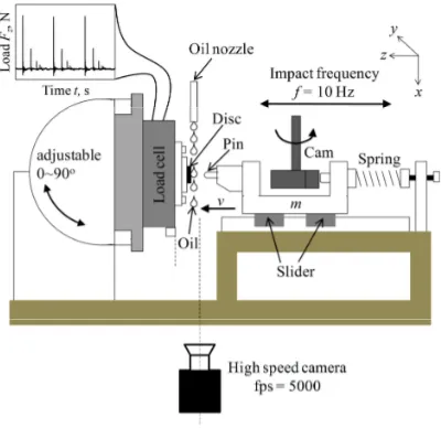
The impact test was performed using a custom made impact tester, as shown in Fig.1. The impact test rig was designed to impact a DLC coated disc with a SCM420 pin for numerous impacts, at a frequency of 10 Hz. The diameter of the disc and the pin were 10 mm and 2 mm, respectively (as shown in Fig.2). Prior to the impact test, both disc and pin were cleaned using acetone in an ultrasonic bath. The DLC coated disc was repeatedly impacted at a 90º inclination. Room temperature kerosene was used as a lubricant. The method of lubrication is illustrated in Fig. 1. All impact tests were conducted at room temperature. The maximum normal impact load was obtained from a load cell. In addition, the impact velocity was determined using a high speed camera.
A Focused Ion Beam (FIB) was used to mill the tested sample, in order to evaluate the wear amount, as well as to examine the cross section of the DLC coating, on the SKH2 substrate. The bonding structures of the DLC coating were studied using Raman spectroscopic analysis. Additionally, surface morphology of worn surfaces on the DLC coating, as well as on the counterpart material, was observed by Atomic Force Microscopy (AFM), Field Emission-Scanning Electron Microscopy (FE-SEM), and Energy Dispersive X-ray Spectroscopy (EDS).
It was assumed that the pin had negligible wear, in so much that no change in its radius took place. Therefore, the mean contact pressure pmean for i impact cycles is
expressed as Eq. (1) [8]:
(
ry rx)
i z imean
a a
F p
π =
, (1)
Where Fz is the maximum normal impact load, ary
and arx are the residual contact radii at the y and x axes,
respectively; which were obtained experimentally for i
impact cycles. The above equation is based on the Hertzian model. However, in reality, the response of the SKH2 substrate to impact was elastoplastic. Thus, in this study, pmean is an approximation of the contact pressure.
Construction methods and a detailed description of the deformation-wear transition map of DLC coating under cyclic impact loading can be found in previous publications [7].
3. Results and Discussion
3.1. Deformation-Wear Transition Map
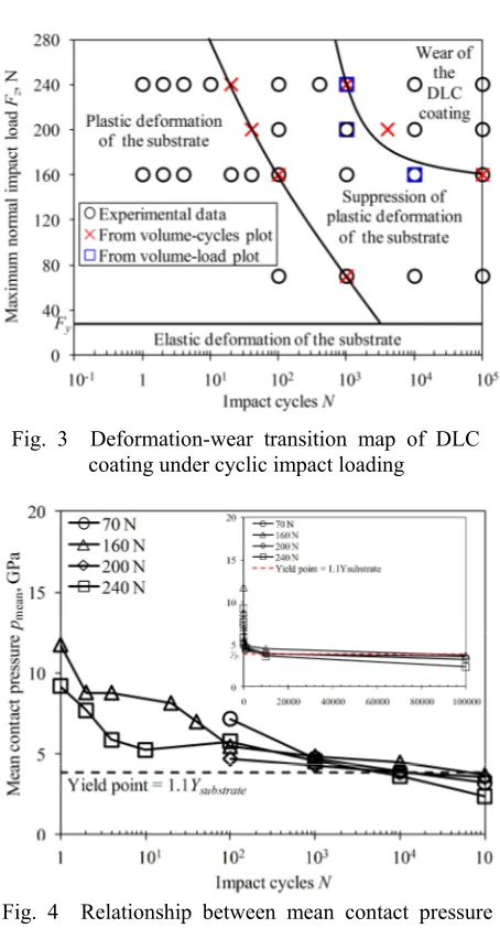
In the present transition map, as shown in Fig. 3, elastic deformation of the substrate zone was added to
the previous transition map [7]. Fy, which was
calculated from the Hertz theory, was the contact load at the elastic limit of the substrate. No crater formation was observed within this zone.
Beyond the elastic limit, the mechanical response of the coating system to a normal load is controlled by the Table 1 Mechanical properties of the DLC, SKH2
substrate, and SCM420 pin
Fig. 1 Schematic illustration of the repeated impact tester
SKH2 substrate for several impact cycles.
The transition between plastic deformation and the suppression of plastic deformation of the substrate was due to the decreasing of contact pressure (calculated from Eq. (1)) to the yield point, as shown in Fig. 4. As the number of impact cycles is increased, the contact area spreads. As this experiment was under the constant maximum normal impact load for each impact cycle, therefore, the contact pressure was decreased. In this zone, the deformation of the substrate was most likely to undergo an elastic deformation if the contact pressure was almost at or below its yield point.
Fig. 3 shows, that by increasing the maximum normal impact load, the suppression of plastic deformation of the substrate taking place, was faster. At 240 N of maximum normal impact load, the plastic deformation of the substrate was suppressed after 101 impact cycles, because the contact pressure started to approach the yield point. However, the plastic deformation of the substrate at 160 N started to suppress after 102 impact cycles for the same reason. As shown in
Fig. 5, almost no wear of the DLC coating was observed within these two zones.
Wear of the DLC coating became predominant when the critical limit of maximum normal impact load and impact cycles was exceeded. According to previous researches, the endurance limit of DLC coating depends on the normal impact load [9-11]. This was in accordance with this study, where a critical maximum normal impact load and a critical impact cycle existed, that would precipitate the wear transition of the DLC coating. Moreover, at this critical impact load and impact cycle, wear gradually increases as material is worn away, due to the phase transformation of DLC coating [9]. This can be verified by a wear depth data collection, as shown in Fig. 5. No wear occurs if the maximum normal impact load is very small; however, a wear transition occurs (due to the impact cycles) when the maximum normal impact load reaches above 160 N,
Fig. 3 Deformation-wear transition map of DLC
coating under cyclic impact loading
Fig. 4 Relationship between mean contact pressure
and impact cycles
Fig. 5 The vertical line pattern shows the approximate wear depth of the DLC coating
Fig. 6 The FE-SEM cross-sectional view of the FIB-milled DLC coating on the SKH2 substrate shows radial crack formation in the
impacted area of the DLC film after 104
as shown in Fig. 3. The DLC coating on the SKH2 substrate achieves extremely high resistance to impact loading (Fz > 240 N) at a low number of impacts (N <
103). In addition, radial cracking was also observed in the coating below the impaction, which initiates from the coating/substrate interface and propagates upwards into the coating, as shown in Fig. 6.
3.2. Future Developments of a Deformation-Wear Transition Map
The present transition map used in this study was originally developed in an attempt to distinguish more clearly between the plastic deformation and impact wear of DLC coating, as well as, to predict its transition points under controlled variables, such as pin radius, coating thickness, substrate material, environmental conditions, etc. So far, the goal to fully map material transitions under different maximum normal impact loads and impact cycles has been successfully met. However, in the case of normal impact, besides the maximum normal impact load, there are still many parameters that induce material loss through the phase transformation of DLC coating.
One of these parameters is impact velocity. A high or low impact velocity, which directly affects strain rate deformation, may also influence the wear of the DLC coating. In addition, high strain rate deformation also results in a significant rise in temperature, due to adiabatic conditions [12]. This can strongly induce the phase transformation of DLC into a graphite-like phase, by a sp3 to sp2 phase transition, at a temperature greater than the graphitization temperature of DLC, of approximately 300ºC [13]. As a result, the DLC coating will easily wear and produce wear debris, while some of it will adhere to a counterpart material as a transfer layer. Fig. 7 shows the AFM topography of a DLC coating that was impacted at two different impact velocities, with the same maximum normal impact load. In addition, the transfer layer on the SCM420 pin was
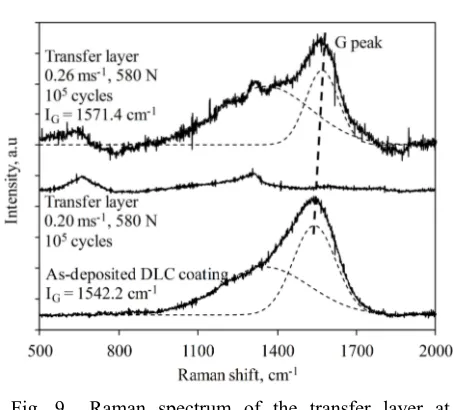
confirmed from the EDS maps for both impact velocities, as shown in Fig. 8. No significant difference was observed for both qualitative analyses. However, a sharp G peak (1571 cm-1) on the Raman spectrum of the transfer layer was found only at the impact velocity of 0.26 ms-1, as shown in Fig. 9. At 0.2 ms-1, no DLC was detected by Raman shift due to its very weak signal in our experimental condition. Raman measurements demonstrated that the G peak position shifted towards a higher frequency (IG = 1571.4 cm-1) compared to the as-received (IG = 1542.2 cm-1). This indicates that the sp2 bonding fraction increased, partial tetrahedral bonds were broken and transformed into trigonal bonds [14]. Then, the sp2 coordinated carbon became gradually dominant and caused phase transformation from sp3 to
sp2, which induced graphitization. The rise of
temperature was believed to be not as high as the graphitization temperature of DLC, since the impact test was performed at room temperature. Therefore, this suggests that based on these preliminary results, the transition of DLC into a graphite-like phase will be accelerated by the higher energy dissipation from impacts between asperities at the tip-coating interface at
Fig. 7 (a) AFM topography of DLC coating after
impacts at two different impact velocities with (b) the same maximum normal impact load for each cycle
Fig. 8 (a) Transfer layer on the SCM420 pin, impacted at the same maximum normal impact load, with two different impact velocities, and (b) EDS map of the transfer layer on the SCM420 pin
Fig. 9 Raman spectrum of the transfer layer at
high velocity.
Other promising parameters that may influence the deformation-wear transition of DLC coating, such as temperature effects, also demand attention. Therefore, as many other possible parameters and areas need to be explored, how this can be incorporated into an existing testing scheme, is a topic that requires extensive research. In order to accelerate this progress, if such a testing scheme and methodology was adopted by many researchers, then future progress could be accelerated.
4. Conclusions
Originally, the deformation-wear transition map was intended to graphically distinguish between the plastic deformation and impact wear of DLC coating, as well as to predict its transition points, over a range of maximum normal impact loads and impact cycles. However, many other parameters exist that may also influence the wear of DLC coating, under cyclic impacts. Based on the preliminary results, besides the maximum normal impact load, impact velocity also influences the graphitization process, due to higher energy dissipation from impacts between asperities at the tip-coating interface, at high velocity. This increases the amount of wear of a DLC coating.
References
[1] Tabor, D., “Status and Direction of Tribology as a Science in the 80s: Understanding and Prediction,” Proc. Int. Conf. Tribol. 80s, 1, 1984, 1-17.
[2] Frost, H. J. and Ashby, M. F., “Deformation
Mechanism Maps: The Plasticity and Creep of Metals and Ceramics,” Pergamon Press, Oxford, New York, 1982.
[3] Elleuch, K., Elleuch, R., Mnif, R., Fridrici, V. and Kapsa, P., “Sliding Wear Transition for The CW614 Brass Alloy,” Tribology International, 39, 2006, 290-296.
[4] Gomes, J. R., Miranda, A. S., Vieira, J. M. and Silva, R. F., “Sliding Speed-Temperature Wear Transition Maps for Si3N4/Iron Alloy Couples,” Wear, 250, 2001, 293-298.
[5] Abdollah, M. F. B., Yamaguchi Y., Akao, T.,
Inayoshi, N., Tokoroyama, T. and Umehara, N., “The Effect of Maximum Normal Impact Load, Absorbed Energy, and Contact Impulse, on the Impact Crater Volume/Depth of DLC Coating,” Tribology Online, 6, 6, 2011, 257-264.
[6] Abdollah, M. F. B., Yamaguchi, Y., Akao, T.,
Inayoshi, N., Umehara, N. and Tokoroyama, T., “Phase Transformation Studies on The a-C Coating Under Repetitive Impacts,” Surface and Coatings Technology, 205, 2, 2010, 625-631.
[7] Abdollah, M. F. B., Yamaguchi Y., Akao, T.,
Inayoshi, N., Miyamoto, N., Tokoroyama, T. and Umehara, N., “Deformation-Wear Transition Map of DLC Coating under Cyclic Impact Loading,” Wear, 274-275, 2012, 435-441.
[8] Johnson, K. L., “Contact Mechanics,” Cambridge
University Press, Cambridge, 1985.
[9] Treutler, C. P. O., “Industrial Use of Plasma
Deposited Coatings for Components of Automotive Fuel Injection Systems,” Surface Coatings and Technology, 200, 5-6, 2005, 1969-1975.
[10] Zanoria, E. S. and Seitzman, L. E.,
“Characterization of Thin Metallurgical Coating Systems by Repetitive Inclined Impact Test in Dry Condition,” Surface Coatings and Technology, 182, 2-3, 2004, 161-170.
[11] Ledrappier, F., Langlade, C., Gachon, Y. and
Vannes, B., “Blistering and Spalling of Thin Hard Coatings Submitted to Repeated Impacts,” Surface Coatings and Technology, 202, 9, 2008, 1789-1796.
[12] Anton, R. J. and Subhash, G., “Dynamic Vickers Indentation of Brittle Materials,” Wear, 239, 1, 2000, 27-35.
[13] Ronkainen, H. and Holmberg, K., “Tribology of
Diamond-like Carbon Film: Fundamentals and Applications,” Eds. by Connet, C. and Erdemir, A., Springer, New York, 2008, 155.