UNIVERSITI TEKNIKAL MALAYSIA MELAKA
OPTIMIZATION OF MACHINING PARAMETERS IN WIRE
EDM
This report submitted in accordance with requirement of the Universiti Teknikal
Malaysia Melaka (UTeM) for the Bachelor Degree of Manufacturing Engineering (Manufacturing Process) with Honours.
by
KW AN CHIN SENG
UNIVERSITI TEKNIKAL MALAYSIA MELAKA
RORANG PENGESAHAN S T:... -r JS LAPORAN PROJEK SARJANA .If UDA
T AJUK: Optimization of Machining Parameters in Wire EDM
SESI PENGAJIAN: 2009/2010
Saya KWAN CHIN SENG (8050610050)
mengaku membenarkan Laporan PSM ini disimpan di Perpustakaan Universiti Teknikal Malaysia Melaka (UTeM) dengan syarat-syarat kegunaan seperti berikut:
1. Laporan PSM adalah hak milik Universiti Teknikal Malaysia Melaka dan penulis. 2. Perpustakaan Universiti Teknikal Malaysia Melaka dibenarkan membuat salinan
untuk tujuan pengajian sahaja dengan izin penulis.
3. Perpustakaan dibenarkan membuat salinan laporan PSM ini sebagai bahan pertukaran antara institusi pengajian tinggi.
4. **Sila tandakan (..J)
D
SULITD
TERHADE1
TIDAK TERHAD(Mengandungi maklumat yang berdarjah keselamatan atau kepentingan Malaysia yang termaktub di dalam
AKT
ARAHSIA RASMI 19n)
(Mengandungi maklumat TERHAD yang telah ditentukan oleh organisasi/badan di mana penyelidikan dijalankan)
dゥセエ[イ。ョ@ oleh:
[ セセ@
(TANDATANGAN PENULIS) Htandatセ@ GAN PENYELIA)
UEWPAYJUN
C op asml. R ·• Falwlti t<ejuruteraan LNNLNセィ@ セ・ュゥャ@ ta
Uneveraiti Teknikal Malaysia . .. Melalca ua n
Alamat Tetap:
13, LORONG GALING 34, JALAN HAJI AHMAD, 25300 KUANTAN, PAHANG
Tarikh: 09t11 APRIL 2010. Tarikh:
q { Jt {
セ|@
t>- Jika Laporan PSM ini SULIT atau TERHAD, sila lampirkan surat daripada pihak berkuasa/organisasi
berkenaan dengan menyatakan sekali sebab dan tempoh PSM ini perlu dikelaskan sebagai SULIT atau
DECLARATION
I hereby, declared this thesis entitled ''Optimization of Machining Parameters in Wire EDM'' is the results of my own research except as cited in references.
Signature
Author's Name Date
ᄋGゥNセᄋ@
ᄋᄋᄋᄋᄋᄋ セ
ᄋ ᄋ ᄋᄋ ᄋᄋᄋᄋ ᄋ ᄋᄋᄋᄋᄋ ᄋᄋ ᄋᄋᄋᄋᄋᄋᄋᄋᄋᄋᄋᄋᄋᄋ@
KWAN CHIN SENG
APPROVAL
This report is submitted to the Faculty of Manufacturing Engineering of UTeM as
a partial fulfillment of the requirements for the degree of Bachelor of Manufacturing Engineering (Manufacturing Process) with Honours. The member of the supervisory committee is as follow:
.. . (Sl . .
]NセセIᄋ ᄋᄋ@
(Official Stamp of Supervisor) UEWPA.YJUN
Pensyaralt
Fakulti Kf'juruteraan ll'embuatan
ABSTRACT
ABSTRAK
Objektif projek ini adalah untuk mengoptimumkan parameter pemesinan dalam teknologi wire electrical discharge machining (WEDM) untuk menghasilkan
elektrod yang berkualiti dan berketepatan. Tujuan elektrod ini adalah untuk digunakan dalam aplikasi pemesinan telus dalam teknologi EDM die-sinking.
Pemesinan bahagian yang kecil dan jitu adalah rumit kerana kewujudan daya mekanikal yang tinggi yang dikenakan dalam kebanyakan process pemesinan yang boleh merosakkan atau mengubah bentuk bahagian. Aplikasi pembuangan bahan dengan penyahcasan elektrik di dalam teknologi WEDM adalah berpotensi untuk
mengatasi masalah tersebut disebabkan keadaan elektrod yang tidak bersentuh dengan bahan kerja dalam process pemesinannya. Dalam projek ini, parameter pemesinan yang telah digunakan dalam kajian ialah open circuit voltage, discharge current dan voltage gap. Response surface methodology (RSM) telah digunakan
untuk mereka eksperimen dan menganalisa keputusan eksperimen. Kualiti dan ketepatan elektrod telah dikaji ke atas kekasaran permukaan dan Iebar pemotongan. Parameter pemesinan yang berpengaruh ke atas kekasaran permukaan ialah open circuit voltage dan voltage gap, manakala parameter pemesinan yang berpengaruh ke
DEDICATION
ACKNOWLEDGEMENT
First of all, I would like to express my gratitude to Universiti Teknikal Malaysia Melaka (UTeM) for the opportunity to pursue study in Bachelor of Manufacturing Engineering (Manufacturing Process) and to conduct and complete this "Projek Sarjana Muda". UTeM has provided many facilities such as machines and equipments to aid the success of this project.
A very special thanks to my supervisor Miss Liew Pay Jun for her guidance, encouragement and contribution in this project. She has given me useful advices and
motivation when I encountered problems and willingly shares the knowledge regarding this project.
Besides that, I would like to thank ADTECH for providing the WEDM machine to
conduct my study and experimental runs. Not forgetting, thanks to Mr. Zamree who is a lecturer in ADTECH that has guided me throughout the entire handling and running of the WEDM machine.
Last but no least, I would like to thank my family for their continuous support and courage throughout the study and the project. Not forgettable, thanks to my friends that have been working side by side in completing this project.
IV
TABLE OF CONTENT
Abstract
Abstrak ll
Dedication lll
Acknowledgement IV
Table of Content v
List of Tables viii
List of Figures IX
List of Abbreviations XI
1.0 CHAPTER 1: INTRODUCTION 1
1.1
Introduction1
1.2
Problem Statement2
1.3
Objective3
1.4
Scope3
1.5
Importance of Study4
1.6
Expected Result4
2.0 CHAPTER 2: LITERATURE REVIEW
s
2.1
Wire Electrical Discharge Machining (WEDM)5
2.1.1
WEDM Process6
2.2
Machining Parameters in WEDM 72.2.1
Open Circuit Voltage 82.2.2
Discharge Current 92.2.3
Voltage Gap 92.3
Response Variables 92.3.1
Surface Roughness10
2.3.2
Kerf Width 112.4
Wire for WEDM12
2.4.1
Brass Wire12
2.5.1
Copper 132.6
Design of Experiment (DOE)14
2.6.1
Response Surface Methodology (RSM)15
2.7
Past Researches on WEDM16
2.8
Summary of Literature Review22
3.0
CHAPTER3:METHODOLOGY
23
3.1
Objective of Experiment23
3.2
Design of Experiment - Response Surface Methodology (RSM)23
3.2.1
Constant Machining Parameter24
3.2.2
Variable Machining Parameter24
3.2.3
Design of Experiment Matrix25
3.2.4
Response Variables26
3.3
Material Preparation27
3.3.1
Workpiece27
3.3.2
Wire27
3.4
Machine and Procedures28
3.4.1
WEDM Machine28
3.4.2
WEDM Machining Procedures29
3.5
Test and Measurement29
3.5.1
Surface Roughness Measurement29
3.5.2
Kerf Width Measurement30
3.6
Data Analysis31
3.7
Discussion on the Results31
3.8
Conclusion and Recommendation31
3.9
FlowChart32
3.9.1
Project Flow Chart32
3.9.2
WEDM Machining Flow Chart34
4.0
CHAPTER 4: RESULTS AND DISCUSSION
35
4.1
Results35
4.1.1
Surface Roughness Measurement35
4.1.2
Kerf Width Measurement37
4.2
Results Analysis by Using Design Expert Software39
VI
4.2.1 Surface Roughness Analysis 4.2.1.1 Transformation
4.2.1.2 Fit Summary 4.2.1.3 セHIBス|@
4.2.1.4 Diagnostics
4.2.1.5 Model Graphs 4.2.2 Kerf Width Analysis 4.2.2.1 Transformation 4.2.2.2 Fit Summary 4.2.2.3 セHIBス|@
4.2.2.4 Diagnostics
4.2.2.5 Model Graphs 4.3 C>ptimization
4.3.1 Numerical C>ptimization 4.3.2 Confirmation Run
5.0 CONCLUSION AND RECOMMENDATIONS
5.1 Conclusion
5.2 Recommendations
REFERENCES
APPENDICES
i\ Gantt Chart for PSM 1 B Gantt Chart for PSM 2
C(i) FX-K Series Machining Data Sheet
C(ii) Names of Machining Conditions Setting Notches C(iii) Notch Settings
D Workpiece and Electrode E Table of Hole Measurement
F Table of Electrode Size Measurement
Vll
© UrWeRIU Tel<nbl Mlllllylla セ@
[image:11.528.39.369.7.706.2]LIST OF TABLES
2.1 Important properties of brass wire in WEDM 13
2.2 Important properties of copper in EDM die-sinking 14
2.3 Journals of past researches on WEDM 16
3.1 Constant machining parameters 24
3.2 Variable machining parameters 24
3.3 Design of experiment matrix 25
3.4 General properties of copper 27
3.5 General properties ofbrass 27
3.6 Specifications ofMitsubishi Wire-Cut EDM FX20K machine 28
4.1 Surface roughness measurement 35
4.2 Kerf width computation 37
4.3 Sequential model sum of square (Surface roughness) 40
4.4 Lack of fit test (Surface roughness) 41
4.5 Model summary statistics (Surface roughness) 41
4.6 Table of ANOVA for Response Surface 2FI Model (Surface roughness) 42 4.7 Table of summary statistics (Surface roughness) 43
4.8 Sequential model sum of square (Kerf width) 61
4.9 Lack of fit test (Kerf width) 62
4.10 Model summary statistics (Kerf width) 62
4.11 Table of ANOVA for Response Surface 2FI Model (Kerf width) 63
4.12 Table of summary statistics (Kerf width) 64
4.13 Solution generated by Design Expert software 80
4.14 Comparison of measurement between the predicted value and actual
value for surface roughness and kerf width 82
4.15 Deviation between the predicted value and actual value for the surface
roughness 83
4.16 Deviation between the predicted value and actual value for the kerf width 83
Vlll
[image:12.528.33.490.79.733.2]LIST OF FIGURES
2.1 Classification of major WEDM research areas 6
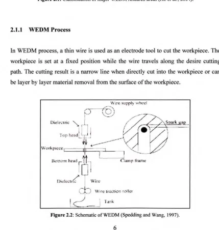
2.2 Schematic ofWEDM 6
2.3 Definition of the arithmetic average height (R3) 10
2.4 Top view of the kerf machined by WEDM 11
3.1 Mitsubishi Wire-Cut EDM FX20K machine 28
3.2 Illustration of cutting mechanism 29
3.3 Mitutoyo Portable Surface Roughness Tester, SJ-301 30
3.4 Mitutoyo Toolmaker's Microscope, TM 30
3.5 Flow chart of project 33
3.6 Flow chart of WEDM machining 34
4.1 Box -cox plot for power transformation (Surface roughness) 39
4.2 Normal plot of residuals (Surface roughness) 44
4.3 Graph of studentized residuals versus predicted values (Surface
roughness) 45
4.4 Graph of externally studentized residuals versus run number (Surface
roughness) 46
4.5 Graph of one factor for surface roughness versus open circuit voltage 47 4.6 Graph of one factor for surface roughness versus discharge current 49
4.7 Graph of one factor for surface roughness versus voltage gap 51 4.8 Perturbation graphs of open circuit voltage (A), discharge current (B) and
voltage gap (C) on the surface roughness 52
4.9 Contour plot of discharge current and open circuit voltage with respond
to the surface roughness 53
4.10 3D surface of discharge current and open circuit voltage with respond
to the surface roughness 53
4.11 Contour plot of voltage gap and open circuit voltage with respond
to the surface roughness 55
lX
4.12 3D surface of voltage gap and open circuit voltage with respond
to the surface roughness 55
4.13 Contour plot of voltage gap and discharge current with respond to the
surface roughness 57
4.14 3D surface of voltage gap and discharge current with respond to the
surface roughness 57
4.15 Cube plot of open circuit voltage (A), discharge current (B) and voltage
gap (C) on the surface roughness 59
4.16 Box-Cox plot for power transformation (Kerf width) 60
4. 17 Normal plot of residuals (Kerfwidth) 65
4.18 Graph of studentized residuals versus predicted values (Kerf width) 66 4.19 Graph of externally studentized residuals versus run number (Kerf width) 67 4.20 Graph of one factor for kerf width versus open circuit voltage 68 4.21 Graph of one factor for kerf width versus discharge current 70 4.22 Graph of one factor for kerf width versus voltage gap 71 4.23 Perturbation graphs of factor voltage open (A), power setting (B) and
voltage gap (C) on the kerf width 72
4.24 Contour plot of factor discharge current and open circuit voltage with
respond to the kerf width 73
4.25 3D surface of factor discharge current and open circuit voltage with
respond to the kerf width 73
4.26 Contour plot of factor voltage gap and open circuit voltage with
respond to the kerf width 75
4.27 Contour plot of factor voltage gap and open circuit voltage with
respond to the kerf width 75
4.28 Contour plot of factor voltage gap and discharge current with respond to
the kerf width 77
4.29 3D surface of factor voltage gap and discharge current with respond to
the kerf width 77
4.30 Cube plot of factors open circuit voltage (A), discharge current (B)
and voltage gap (C) on the kerf width 79
2FI AISI ANN ANOVA
c.v.
Cr DC53 DOE EDM FEA lACS MRR NSGA PRESS RSM SA SKDll SUS-304 WEDMLIST OF ABBREVIATIONS
2-Factor Interactions
American Iron and Steel Institute Artificial Neural Network
Analysis of Variance Coefficient of Variation Chromium
Tool steel
Design of Experiment
Electrical Discharge Machining
Finite Element Analysis
International Association Cryospheric Sciences Material Removal Rate
Non-dominated Sorting Genetic Algorithm
Predicted Residual Sum of Squares Arithmetic Average Height
Response Surface Methodology Simulated Algorithm
Hardened steel Stainless steel
CHAPTER I
INTRODUCTION
This chapter includes the overview of wire electrical discharge machining (WEDM).
The problem statement and objective of the study are also included. Then, it is
followed by the scope, importance of study and expected result of the project.
1.1
Introduction
According to Ho eta/. (2004), WEDM is a specialized thermal machining process
capable of accurately machining parts with varying hardness or complex shapes,
which have sharp edges that are very difficult to be machined by the main stream
machining process. Since the introduction of the process, WEDM has evolved from a
simple means of making tools and dies to the best alternative of producing
micro-scale parts with the highest degree of accuracy and surface finish quality.
Sanchez and Ortega (2009) stated that WEDM is unique that the machining process
does not involve mechanical force exerted on the workpiece whereby material is
removed by a series of discrete electrical discharge (spark) generated between a
workpiece and wire electrode under the localized stream of dielectric fluid.
Throughout the cutting process, the wire electrode is continuously fed and collected
by spools or nozzles at certain speed and the movement of the wire electrode is controlled numerically to cut the desired path and dimension of the workpiece.
Prasad and Krishna (2008) explained that generally, the selection of optimal
parameters in WEDM is difficult as it is a complex process and involves a large
dependent on the operator' s experience and machining parameter tables provided by the machine-tool manufacturers. However, researches have been carried out widely by various researchers in optimizing the machining parameters on various materials and conditions to obtain the desired machining result in WEDM.
Kohkonen (2009) intorduced that WEDM process found extensive use in producing parts, especially small parts with low wall thickness. The wire electrode and workpiece never make contact where there is virtually no cutting force on the part. This allows for small parts with thin wall sections to be cut without deformation. Furthermore, Hewidy et al. clarified that the high degree of the obtainable accuracy and the fme surface quality make WEDM valuable in miniature application. This has made WEDM process to surpass most of the conventional machining process.
1.2
Problem Statement
Besides than WEDM, electrical discharge machining is also applied in the means of die-sinking where the same electrical discharge concept is used but having a shaped electrode tool being directed towards the surface of the workpiece. The electrode in EDM die-sinking needs to be machined to the desire shape and size, where some would have intricate shape and low cross-section. The electrode is hardly producible by the conventional machining method. It is more crucial when the electrode is used for miniature machining in EDM die-sinking where the electrode is of high length to cross-section ratio. It is easily subjected to deformation by only little forces.
Besides that, in order to get a good quality of miniature machining in EDM
die-sinking, the electrode must be of good quality and accuracy. According to Mahapatra
and Amar (2007), the quality of the electrode is determined by the low surface
roughness of the machined surface while the accuracy of the electrode is determined
by the small kerf width of the WEDM process. Ho et al. (2004) stated that the
settings for various process parameters required in the WEDM process play a crucial
role in producing an optimal machining performance.
1.3
Objective
1. To optimize the machining parameters in WEDM in fabricating a quality electrode with good surface finish and accuracy for the application of
miniature machining in EDM die sinking.
2. To determine the significant machining parameters and study the interaction
between the machining parameters and responses involved.
1.4
Scope
This project included the study on the few variable machining parameters in WEDM
which are open circuit voltage, discharge current and voltage gap. The other
machining parameters such as pulse-off time, wire speed, wire tension, dielectric
flow rate and dielectric flow rate are set constant. The performance measures of the
study are evaluated on the surface roughness of the electrode and the kerf width of
the WEDM process. Response surface methodology (RSM) method is used to study, analyze and relate the variables and responses involved. The significant machining
parameters in WEDM are obtained. Finally, mathematical model is developed to
represent the study and verification is conducted to determine the consistency of the
1.5
Importance of study
The primary concerns in this study are the surface finish of the electrode and the kerf width of the WEDM process, where both are of high importance in small precision parts. The surface roughness determines the surface quality of the electrode, while the kerf width determines the accuracy of the electrode. The quality of the electrode machined for the application of miniature machining in EDM die-sinking is important because it reflects the resulting machining surface and accuracy. The optimized machining parameters of the study can also be used as a reference to
fabricate other intricate shapes such as tools and dies, fixtures and gauges, prototypes and medical parts with the identical workpiece feature and machining condition.
1.6
Expected result
CHAPTER2
LITERATURE REVIEW
This chapter includes the theory of the fundamentals involved in the study. Besides
that, the related findings by past researchers are also included. At the end of this
chapter, a summary of the study is included.
2.1
Wire Electrical Discharge Machining (WEDM)
Spedding and Wang (1997) stated WEDM has grown tremendously in conductive
material machining recently because of its advantages of being unaffected by
material hardness, no cutting force, high accuracy, and the ability to achieve complex
workpiece shape as well as unmanned machining. Performance of the WEDM
process, however, is affected by many factors (workpiece material, wire, dielectric
medium, adjustable parameters, etc.) and a single parameter change will influence
the process in a complex way.
Tosun et al. (2004) conducted the survey of literature review and indicates that there
are published works on the effect of machining parameters on material removal rate
(MRR), surface roughness, cutting speed, wire rupture and wire craters.
Unfortunately, little research related to the kerf width variation has been done. Di et
a/. (2009) presented that it is significant to investigate the kerf variations in detail to
Optimizing the Process Variables
WEDM
Research Areas
Monitoring &
Control the Process
Process Parameters Design
Fuzzy Control System
WEDM Developments
WEDM Applications
Process Modeling Wire Inaccuracy
Adaptive Control Systems
t_.___
Hybrid Machining Processes
Self-Tuning Adaptive Control
Systems
[image:21.528.42.489.45.581.2]L
Figure 2.1: Classification of major WEDM research areas (Ho eta/., 2004).
2.1.1 WEDM Process
In WEDM process, a thin wire is used as an electrode tool to cut the workpiece. The
workpiece is set at a fixed position while the wire travels along the desire cutting path. The cutting result is a narrow line when directly cut into the workpiece or can
be layer by layer material removal from the surface of the workpiece.
cl:J
Wtrc ll a ;: tl Oil rolk•セ セ
M]@
' fd n [image:21.528.32.462.317.770.2]Sanchez and Ortega (2009) demonstrated that during cutting, electrical discharges
occur within the continuous flushing of dielectric fluid. The dielectric fluid used in
most WEDM machines is deionized water. During the application of each discharge,
local temperature rises by several thousand degrees (ranging between I
0,000°C-20,0000C). Consequently, part of the material melts and vaporizes generating craters
on the surface of the workpiece, which is removed in the form of debris by dielectric
flushing. As the gap between the workpiece and wire is very small (ranges from
0.025 to 0.05 mm), it is difficult to sufficiently flush the cutting zone especially when
the part thickness is high. For that reason, most machining work is done in a
completely filled tank and the workpiece is submerged fully in the dielectric fluid.
By referring to Prasad and Gopala (2008), the relative movement between the
workpiece and wire is controlled numerically to get the required shape and accuracy
of workpiece. The gap between the workpiece and the wire is maintained at an
effective distance by servo control system. As it cuts, the wire is continuously fed
and pulled by an automatic take-up mechanism. Sanchez and Ortega (2009) also
explained that as the wire is constantly renewed, it provides a constant-diameter wire to the cutting and the wire wear is not a primary concern.
2.2
Machining Parameters in WEDMHo et a/. stated that WEDM process is a complex process involving a wide range of
machining parameters. Generally, the machining parameter settings can be obtained
from the manufacturer guide but the machining settings provided might not be
optimal due to the machining diversity. Levy and Maggi (1990) demonstrated that the parameter settings given by the manufacturers are only applicable for common
steel grades.
Scot et a/. (1991) found that discharge current, pulse duration and pulse frequency
were the main significant control factors for both MRR and surface finish, while wire
speed, wire tension and dielectric flow rate were relatively significant. Tamg et a/.
(1995) found that the machining parameters such as the pulse on/off time duration,
capacitance and table speed are the critical parameters for the estimation of the
cutting rate and surface roughness.
Mahapatra and Amar (2007) presented that based on the analysis of variance, it was found that the discharge current, pulse duration and pulse frequency are significant control factors for both the MRR and surface roughness. Tosun et aJ. investigated that the most effective parameters with respect to kerf width are open circuit voltage and pulse duration whereas the effect of wire speed and dielectric flushing pressure on the kerf was insignificant.
From the literature review in machining parameters, the surface roughness is mostly affected by discharge current, pulse duration, pulse-off time and open circuit voltage, while the kerf width is mostly affected by open circuit voltage and pulse duration. The variable machining parameters selected through the literature review and with accordance to the restraint of the machine used were open circuit voltage, discharge current and voltage gap.
2.2.1 Open Circuit Voltage
2.2.2 Discharge current
Discharge current refers to the peak current between poles. Hewidy et al. (2005)
presented that the increase in peak current causes an increase in discharge energy at
the point where the discharge takes place. Discharge current must be set to
commensurate with workpiece materials and wire electrode. Hewidy et al. (2005)
also stated that successive discharges that have random nature will result in the
formation of overlapped crater, pockmarks and chimneys. The diameter and the
depth of the crater depend on the discharge energy or in other words, on the peak
current value. Sanchez and Ortega (2009) found that accuracy can be greatly
improved by using low energy system.
2.2.3 Voltage Gap
Voltage gap is an average machining voltage used as a guideline value to machine
with optimum feed. Elman (200 1) stated that this voltage gap value fell from the
open circuit voltage when the machining starts to generate spark. Sanchez and Ortega
(2009) presented that the voltage gap, which is governed by the servo of gap, plays a
determining role in the evacuation of debris. Liao et al. (2004) stated that smaller
voltage gap ensure the occurrence of discharging spark but the electrostatic force
between the anode and cathode will increase. Therefore, wire deflection increase and
make it difficult to operate finishing process. This reflects on the surface finish and
the accuracy of the resulting machining.
2.3
Response Variables
According to Mahapatra and Amar (2007), the most important measures in WEDM are セ@ surface roughness and kerf width. Among other performance measures,
the kerf width, which determines the dimensional accuracy of the finishing part, is of
extreme importance. In WEDM operations, MRR determines the economics of
machining and rate of production. Besides that, the surface roughness is important