DESIGN AND ANALYSIS A NEW SYSTEM FOR DUCT TESTING WITH THE SMART INSTALLATION METHOD
SYUKUR BIN ABDUL KADIR
Thisreportpresentedin partial fulfillmentof therequirements for the graduation of Bachelor of Mechanical Engineering (Design &Innovation)
FakultiKejuruteraanMekanikal
UNIVERSITI TEKNIKAL MALAYSIA MELAKA
i
“I declare that I had read this thesis and in our opinion this thesis is sufficient from the aspect of scope and quality for the purpose to be awarded Degree of Bachelor
Mechanical Engineering (Design and Innovation)”
ii
“I hereby to declare that this project report entitle Development and Characterization of Design and Analysis a New System for Duct Testing with the Smart Installation Method
s written by me and is my own effort except the ideas and summaries which I have clarified their sources.”
Signature : ………
iii
iv
ACKNOWLEDGEMENT
Assalamualaikum w.t.h, and Salam Sejahtera. With the word Alhamdulillah and very gracefully thanks to ALLAH s.w.t, for give much blessing to me in equally well to complete this project. With His permission, I have success in facing the challenge any obstacle while in completing this project.
This appreciation is also given to my project supervisors Projek Sarjana Muda, Mr. Nazri Huzaimi bin Zakaria cause willing to take the idea of my project’s proposal to be one of the topic research in this Projek Sarjana Muda. And also thankful once again causes have much helping and guide me to complete the project.
I am also not forgetting the Quality Assurance Engineer En Hafidzul as much taught and provides a very meaningful experience in my industrial training. A very thankful to En Hafidzul cause allows me to take this project for my Projek Sarjana Muda.
v
ABSTRACT
vi
ABSTRAK
Penyelidikan ini adalah salah satu usaha untuk mereka bentuk semula sistemujikaji lohong “Duct Testing” yangsediaadadengan konsep pemasanganpintaryangmana sistem inidigunapakaidi dalamBahagian Kualitidi syarikatSalutary Avenue. Kaedah-kaedah untuk membangunkanrekabentukbaruini adalahmeliputi proses-prosesyang berkaitan denganmembuatkeputusan melalui kaedah perbandingan yang berbezamengikut aktiviti setiapperingkat. Proses penambahbaikan ini akan akan mewujudkan reka bentuk baruyanglebihergonomikdenganpekerjayangakan mengendalikansistem tersebut. Kajian ini dilakukan berdasarkan permasalahan yang berlaku ketika tempoh 3 bulan Latihan Industri di syarikat ini. Semasa tempoh tersebut,segala pengetahuan mengenai sistem ini diperoleh dengan memahami manual dan butiran-butiran terperinci yang berkaitan. Setelah membuat beberapa perbincangan bersama Jurutera Kualiti merangkap penyelia, beberapamasalahdapat di kenalpasti daripada pengalamandanaduandaripada pelanggan. Olehitu, berdasarkanmasalahyang telah dikenalpasti, penjanaan semula reka bentuk sistem yang baru akan dilakukan dengan mengaplikasikan sistem pemasangan pintar. Pemasanganpintardisinibermaksud
mempunyai bahagian badanyang lebih ergonomikdimana
vii
TABLE OF CONTENT
CHAPTER TITLE PAGE
CONFESSION i
DECLARATION ii
ACKNOWLEDGEMENT iv
ABSTRACT v
ABSTRAK vi
TABLE OF CONTENT vii
LIST OF TABLE xii
LIST OF FIGURE xiii
LIST OF APPENDICES xvi
CHAPTER 1 INTRODUCTION 1
1.1 Background Company 1
1.2 Quality Management System 2
1.3 Duct Testing System 4
1.4Problem Statement 6
1.5 Objectives 7
viii
CHAPTER 2 LITERATURE REVIEW 8
2.1 Backgrounds 8
2.2 Wind Tunnel 9
2.3 Fluids Dynamics
102.3.1 Airflow in turbulent 10
2.3.2 Fluid Viscosity 11
2.3.3 Reynolds Number 11
2.3.4 Boundary Layers 13
2.4 Designs in Ducting
142.4.1 Open Circuit 142.4.2 Closed circuit 152.4.3 Fans
162.4.4 Settling Chamber 162.4.5 Honeycombs 16 2.4.6 Diffuser 17 2.4.7 Test Section 17
2.5 Testing Area with Application
182.5.1 Velocimeters/Observation Devices 18 2.5.2 Dust Feeder
192.5.3 Atomizer
Aerosol Generator 20
2.5.3.1 Principle
212.5.3.2 Technical Data
222.5.3.3 Other
Generators
(Series ATM) 22
2.5.4 Laser Aerosol Particle Counter 23
ix
CHAPTER 3 METHODOLOGY 27
3.1 Introduction 27
3.2 Flow Chart 28
3.3 Identifying the Tester andCustomer Need 29 3.3.1 Formulating a Design problem 30 3.4 Quality Function Deployment (QFD) 31
3.4.1 List of Need Statement 32
3.4.2 House of Quality
333.4.3 Summary 34
3.5 Product Design Specification 343.6 Morphological Chart 36
3.7 Design Tools 37
3.7.1 Rough 3D Drawing 37
3.8 CAE Analysis 38
3.8.1 Finite Element Analysis (FEA) 38 3.8.2 Computational Fluid Dynamics 39
3.8.3 Analyses Results 40
3.9 Conceptual Design 40
3.9.1 Concept 1 41
3.9.2 Concept 2 42
3.9.3 Concept 3 43
3.10 Weight decision Method
x
CHAPTER 4 DESIGN ANALYSIS AND RESULT 47
4.1 Introduction of Design Analysis 47 4.2 Target Outcome of Design Analysis 48
4.3 Overview of Detail Design 49
4.4 Finite Element Analysis (FEA)
Using ANSYS V12 54
4.4.1 Structure Analysis in
Existing Concepts (Acrylic 5mm) 56 4.4.2 Structure Analysis in Parameter 2
(Acrylic 8mm) 57
4.4.3 Structure Analysis inParameter 3
(Acrylic 10mm) 59
4.4.4 Calculation of Safety Factor 60
4.4.5 Analysis Summary 62
4.5 Computational Fluid Dynamic 63
4.5.1 Selection Concepts 64
4.5.2 Analysis Summary 65
4.6 Installation Method & Testing Procedure. 65 4.6.1 Installation (First Setup) 66
4.7 Maintenance 70
4.8 Cost Analysis 73
4.8.1 Material Used 73
4.8.2 Estimation Cost 75
xi
CHAPTER 5 DISCUSSION 78
5.1 Overview of Idea Improvement 78
5.2 Evaluating Results 81
5.2.1 Analysis Structure (Static & Flow) 81 5.2.2 Time and Man Power Reduction
in Process Installation 84
5.2.3 Cost Management 85
CHAPTER 6 CONCLUSION AND RECOMMENDATION 86
6.1 Conclusion 86
6.2 Recommendation 88
BIBLIOGRAPHY APPENDICES A Gantt chart B Details design
xii
LIST OF TABLE
NO TITLE PAGE
2.1 Technical Data of Aeorosol Generator 22
2.2 Summary of Application 24
3.1 House of Quality 33
3.2 Product Design Specification Characteristic 35
3.3 Morphological chart 36
3.3 Weight Decision Metric 45
4.1 Bill of Material (BOM) 52
4.2 Material Properties 55
4.3 Material Properties 55
4.4 Analysis Summary 62
4.5 Analysis Summary 65
4.6 Comparison Design in Maintenance 71
4.7 Estimation Cost by Each Component 75
xiii
LIST OF FIGURE
NO TITLE PAGE
1.1 Filter testing with existing Duct System 5
1.2 Testing area with equipment 5
2.1 Wind tunnel factory ventilation (right) 9
2.2 Experiment aircraft 9
2.3 Air flow pattern in ducting 12
2.4 Open circuit Ducting 14
2.5 Closed circuit Ducting 15
2.6 Testing Area Filter 17
2.7 Dust Feeder Application 19
2.8 Atomizer Aerosol Generator
202.9 Laser Aerosol Particle Counter 23
2.10 Arrangement of instruments Aerosol Generator ATM,
Dust Feeder 24
2.11 Airpak filter (Pre Filter) 26
2.12 XL FOLD Filter (fined filter) 26
xiv
3.1 Flow Chart 28
3.2 Information required for the production
of the product design specification (after Pugh, 1990) 34
3.3 Concept 1 41
3.4 Concept 2 42
3.5 Concept 3 43
3.6 Object Tree 44
4.1 Assembly Component 49
4.2 Exploded Components (inlet ducting) 50
4.3 Exploded Components (testing area) 50
4.4 Exploded Components (outlet ducting) 51
4.5 Inlet Ducting 53
4.6 Testing Area 53
4.7 Load Applied and Fixed support 54
4.8 Equivalent (Von-Mises) Stress after Analysis 56
4.9 Total Deformations after Analysis 56
4.10 Safety Factor of 5mm 57
4.11 Equivalent (Von-Mises) Stress after Analysis 57
4.12 Total Deformations after Analysis 58
4.13 Safety Factor of 8mm 58
4.14 Equivalent (Von-Mises) Stress after Analysis 59
xv
4.16 Safety Factor of 10mm 60
4.17 Comparison Design in Sketching 63
4.18 Velocity Streamlines Concepts 1 64
4.19 Velocity Streamlines Concepts 2 64
4.20 Process 1 66
4.21 Process 2 67
4.23 Process 3 68
4.24 Worker Crawl inside Ducting to Clean Up Mud 70
4.25 Inlet Area 71
4.26 Testing Area 72
4.27 Outlet Area 72
4.28 Standard Part 74
5.1 Flow Generation Idea
795.2 Flow Selected Concepts to Details Design 80
5.3 Graph Von Mises vs. Parameter 82
5.4 Graph Deformation vs. Parameter 82
xvi
LIST OF APPENDICES
NO. TITLE
A Gantt chart PSM I and II
B Details Design
CHAPTER 1
INTRODUCTION
1.1 BACKGROUND COMPANY
Salutary Avenue Manufacturing Services SdnBhd (SAM) is established in the early 90s with networks throughout the region and having its headquarters in Malaysia. The Company specializes in designing, manufacturing, installing and monitoring of filters for the application in the power and oil and gas industries.
The companies were awarded the prestigious ISO 9001:2000 in August 2003 by Lloyd's Register Quality Assurance and the scope of Quality Management System is applicable to design, development and manufacture of intake air filter and liquid filter.SAM possesses the technical know-how and manufacturing capabilities to produce top quality filters to cater for customers' requirements. The R&D teams are categorized into three divisions namely:-
i. Product Improvement Team looks into the ongoing improvements of existing products
ii. New Product Development Team develops new filter ranges which are widely used by our customers or required by them in order to solve existing problems
2
This company has close collaborations with local institutions for updating and developing latest technologies and utilizing their facilities. The company also have own in-house testing facilities which conform to international standard. Several plants with an overall land area of 60,000 sq. feet, equipped with machinery, fittings and related facilities. The existing production capacity today is 800,000 units yearly and able to facilitate further for twice the existing capacity and also provide technical and consultation services as follows:-
i. Technical presentation on filter fundamentals, awareness and knowledge to educate engineers andend-users
ii. Perform data analysis on filter efficiency and savings on cost of energy iii. Continuous technical support and professional advice on filter
The company also offers packaged services such as monitoring and inspection of the filters so as to ensure their consistent maximum performance. Monitoring is crucial
i. To eliminate any unnecessary maintenance to gas turbine and turbo compressors
ii. To ensure low power consumption cost by reducing maintenance cost resulting from premature shut down of gas turbine
1.2 QUALITY MANAGEMENT SYSTEM
3
The management of Salutary Avenue is committed to the design and production of filter that is fit for its purpose, highest quality consistent with its performance and offers safety and reliability at the optimum price and product availability. This is achieved by operating and maintaining a comprehensive quality control system based on ISO 9001:2000. The system is fully documented and has taken place in three stages as categorized below:-
Quality Inspection
A group of inspectors and checkers is available to perform tests and comparison of the product with the standard. This was applied at all stages covering the raw material received, production process and delivery. The purposes of the inspection is to identify defects found during inspection and segregates them for scrapped, reworks or degrade to second products.
Quality Assurance
4
1.3 DUCT TESTING SYSTEM
Air filter test rig dust feeder fitted with vibrating tray to add measured quantity of the dust. 200mm dia. Ducting will be used in test equipment. Duct fitted with piezometer ring on the upstream and downstream for measurement of pressure drop across the test filter. Provision is for the mounting of test filter. Test filter housing suitable to mount filter of 980mmheight. Ducting mounted on trolley for easy mounting of test filter and loading and unloading of HEPA filter. Provision is for the mounting of HEPA filter with conical duct at both ends. Airflow measuring unit is apply with orifice plate and pressure tapping across it. And the Butterfly valve is to adjust different flow rate. Blower impeller directly mounted on the shaft of the motor. Tapping for particle counter fitted with solenoid valve for taking upstream and downstream count. Control panel for the above. Air filter test rig. The performance air filter test rig that is designed to serve various industrial applications. Outfitted with various attributes, this fuel filter testing rig is manufactured from high quality material.
5
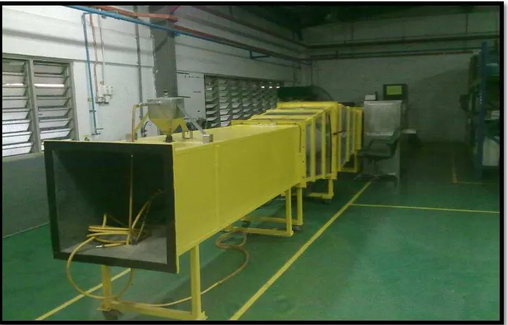
Figures 1.1: Filter testing with existing Duct System
Figures 1.2: Testing area with equipment
6
The data problem statements are getting from the customer complaint with Salutary Avenue Companyand from the experience while handling the system in my Industrial Training. For the complaint document is not provide in this report because it be the confidential.
The major problem is the time taken while handling the system which in term of installing the filter, running the test and collecting data. The time process are not ergonomics that means the scientific discipline concerned with the understanding of interactions among humans and other elements of a system, and the profession that applies theory, principles, data and methods to design in order to optimize human well-being and overall system performance.
Tocomplete the testing procedure or step, it must need at least three people to in charge the process. The new target for the new ducting system will capable running only uses 2 or 1 person. By reducing man power it also affected the cost in implementation the quality testing.
Another problem that occurs in the duct testing system is the design problem. The old design have difficult problem in maintenance. For the maintenance, after completing the dust and water testing the problems happen in cleaning up the body. And the leaking problem in piping also occurs after the test.
The body is capable to test only 2 stage filter, meanwhile the customer request the process are in 3 stage in one time process which is include pre, fined and HEPA filters.
Due to the problem, a study and analysis for the existing product must be done to make the improvement of duct testing design with smart installation. A new design is expected to solve the problems that happen earlier.
7
The objectives of this study are to design and analysis a new duct system testing with a new concept of duct system by focusing on smart installation method.
1.6 SCOPE OF PROJECT
The scopes for this project are:
i. Study and analyze the existing design of ducting system.
ii. Design a new concept of duct testing system with smart installation method.