Faculty of Electrical Engineering
DESIGN AND DEVELOPMENT OF SIT-TO-STAND
TRAJECTORY AND CONTROL OF HUMANOID ROBOT
Mohd Bazli Bin Bahar
Msc. of Science in Mechatronic Engineering
DESIGN AND DEVELOPMENT OF SIT-TO-STAND TRAJECTORY AND
CONTROL OF HUMANOID ROBOT
MOHD BAZLI BIN BAHAR
A thesis submitted in fulfilment of the requirements for the award of
The degree of Master of Science in Mechatronic Engineering
Faculty of Electrical Engineering
UNIVERSITI TEKNIKAL MALAYSIA MELAKA
DECLARATION
I hereby declare that this thesis entitled ―Design and Development of Sit-To-Stand Trajectory and Control of Humanoid Robot‖ is the result of my own research except as cited in the references. The thesis has not been accepted for any degree and is not concurrently submitted in candidature of any other degree.
Signature :………
ii APPROVAL
I hereby declare that I have read this thesis and in my opinion this thesis is sufficient in terms of scope and quality for the award of Master of Science in Mechatronic Engineering.
Signature :………
iii
DEDICATION
i ABSTRACT
Sitting position is an important feature in a humanoid robotic system as it is more stable when compared to standing position, resulting in less energy consumption since no actuator is needed to stabilize the robot. Sitting is crucial especially for humanoid robot in security and domestic robotics field where the robots are used for a long period. In order to return to standing position, sit to stand (STS) motion is needed. One of the main challenges in STS is during the lift-off; i.e. the moment when the robot’s thigh is lifted from the chair’s surface. During lift-off, a sudden change of the position of centre of mass (CoM) causes instability to the STS motion. Furthermore, the limitation of body and joint will exacerbate the problem by limiting the ability to move the CoM to appropriate position. Due to this issue, the first objective of this research is to develop and validate a system that autonomously able to identify a trajectory to transfer the CoM to an appropriate position before lift-off from any chair height. The method works by autonomously calculate the horizontal distance between the CoM and the support polygon. With the estimated distance, flexion of hip and ankle joints is made to bring the CoM into the support polygon. The arrangement of the motion is based on Alexander STS technique. Second objective is to develop and validate a control system to balance the robot from tumbling down during STS motion due to stability issue. The proposed control system employs the IF-THEN rules as the action selector. The rules are set based on CoP position and feedback from body’s angular direction in y-axis on sagittal plane. The rules set three variable i.e. HAT (Head-Arm-Torso) direction, HAT velocity, and proportional controller gain. To determine the gain for the proportional controller, the gain identification method implements the partitioning of CoP position into a number of regions. The coefficient at each region is set differently to increase the sensitivity of the controller. To verify the effectiveness of the proposed method, experiments using NAO robot were conducted. The stability of the robot was measured based on the position of Centre of pressure (CoP) within the feet area and the angle y reading. Results show that the robot was able to perform the STS motion when height of chair is varied from 9.95cm to 16.25cm. The CoP position also shows that the pressure point is always within the feet area. However, the system failed to perform the task when the height of chair is lower than 96.60% of the robot’s shank length due to the
ii ABSTRAK
Posisi duduk merupakan ciri penting bagi robot humanoid kerana ia lebih stabil berbanding dengan posisi berdiri, dan ini menyebabkan penggunan tenaga yang kurang kerana tiada unit penggerak diperlukan untuk mengekalkan kestabilan. Kriteria ini penting untuk robot yang digunakan bagi tujuan keselamatan dan domestik yang beroperasi dalam jangka masa yang lama.Untuk kembali ke posisi berdiri, pergerakan bangun atau ‘sit to
iii
ACKNOWLEDGEMENT
First and foremost, I would like to take this opportunity to express my sincere acknowledgment to my supervisor Dr. Muhammad Fahmi Bin Miskon from Faculty of Electrical Engineering Universiti teknikal Malaysia Melaka for his supervision, support and encouragement towards the completion of this thesis.
I would also like to express my gratitude to Engr, Norazhar Abu Bakar from Faculty of Electrical Engineering Universiti teknikal Malaysia Melaka, co-supervisor of this project, members of CERIA laboratory, Dr. Ahmad Zaki Bin Shukor, and Dr. Fariz Bin Ibrahim for advices and suggestions during completing this thesis.
Special thanks to UTeM, study leave department, Faculty of Electrical Engineering and Kementerian Pelajaran Malaysia (KPM) for the financial and technical support given throughout this project.
iv
TABLE OF CONTENT
PAGE
DECLARATION i
APPROVAL
DEDICATION
ABSTRACT i
ABSTRAK ii
ACKNOWLEDGEMENT iii
TABLE OF CONTENT iv
LIST OF TABLES viii
LIST OF FIGURES ix
LIST OF APPENDICES xi
LIST OF ABBREVIATIONS xii
LIST OF PUBLICATION xiii
CHAPTER
1. INTRODUCTION 1
1.1 Research Background 1
1.1.1 STS problem. 2
1.2 Problem statement 4
v
1.4 Scope of research 7
1.5 List of contributions 7
1.6 Significant of study 8
2. LITERATURE REVIEW 9
2.1 Introduction 9
2.2 Robotic system overview 9
2.3 STS motion 11
2.3.1 Challenges in STS motion 12
2.3.2 Trajectory planning to perform STS motion 13
2.3.3 Control mechanism in STS motion 16
2.3.4 Benefit of STS motion study 22
2.4 Conclusion 23
3. RESEARCH METHODOLOGY 25
3.1 Introduction 25
3.2 System configuration 25
3.2.1 CoM position 26
3.2.2 Region boundaries 27
3.3 The Proposed STS Method 29
3.3.1 CoM transferring 31
3.3.2 Stabilization strategy 39
3.4 Research Methodology: Laboratory Experiment 48
vi
3.4.2 General experimental setup 51
3.5 Summary of Chapter 3 56
4. RESULTS & DISCUSSION 57
4.1 Introduction 57
4.2 Validation of problem statement 57
4.2.1 Results 58
4.2.2 Discussion 59
4.3 Implementation of Alexander STS technique (forward hip bend) 59
4.3.1 Results 61
4.3.2 Discussion 61
4.4 Implementation of Alexander STS technique (upward ankle bend) 62
4.4.1 Result 63
4.4.2 Discussion 63
4.5 Horizontal Distance Identification (HDI) and Joint Angle
Determination (JAD) Algorithm 64
4.5.1 Results 65
4.5.2 Discussion 68
4.6 STS control algorithm using IF-THEN rules 70
4.6.1 Results 71
4.6.2 Discussion 73
4.7 The effect of implementing hip and ankle joint change limitation 74
vii
4.7.2 Discussion 77
4.8 Gain coefficients identification. 78
4.8.1 Results 78
4.8.2 Discussion 82
4.9 STS motion from multi chair height. 85
4.9.1 Result 86
4.9.2 Discussion 89
5. CONCLUSIONS & RECOMMENDATIONS 93
5.1 Conclusions 93
5.2 Recommendations 95
REFERENCES 97
APPENDIX A – Experiment on power consumption 106
APPENDIX B – Inertial Unit Datasheet 108
APPENDIX C1 – CoM transferring phase algorithm 112
APPENDIX C2 – Whole body velocity representation algorithm 115
APPENDIX D – Alexander STS technique 117
APPENDIX E1 – Robot motion at 11.00cm 118
viii
LIST OF TABLES
TABLE TITLE PAGE
1.1 3.1 4.1 4.2 4.3
4.4
4.5
Lower limb joint maximum flexion. 4
DH parameter for lower limb of NAO robot. 49
Angle y and CoP reading when chair height is varied. 65 The effect of increasing change time to the angle y trajectory. 68 Actual environment (AE) results with implementation of the IF-THEN
rules. 71
Actual environment result with implementation of joint change
limitation. 75
ix
Basic of robotics system. 10
STS cycle diagram, phase, activity and event marker definitions. 14 Position of HAT, thigh and shank mass ( ��, , ) located at the
centre of the link. 26
Robot footsole. 27
Experiment result using NAO robot. 28
Overall system overview for autonomous sit to stand motion 30 Overall system overview for stable sit to stand motion 31 The initial position of NAO robot at sitting position. 31
Position of � , , and . 34
The first graph represents the displacement of a joint from -10 degree to 45 degree within 2 seconds. The second graph is the velocity
trajectory and the last one is the acceleration trajectory of the joint. 38 Region defines at robot foot base on CoP position. 40
Coefficient label in the defined region. 43
Position of coefficient 1, 2, and 3 refer to the motion trajectory. 45 Location of weight, m and the link of whole body link, and body
link, . 46
NAO robot dimension (Front). 49
Position of FSR at the robot foot. 50
Overview of angle y and angle x position. 51
General system overview with plan experiment position. 52
The initial sit position of NAO robot. 53
x
Angle y graph for plan and actual trajectory when using NAO robot. 59 Trajectory of hip, knee, and ankle joints. Hip joint starts 0.5 second
earlier to bend forward. 60
Angle y graph for plan and actual trajectory when using NAO robot
with hip joint flexion. 61
Trajectory of hip, knee, and ankle joints. Hip joint and ankle joint start
0.5 second earlier to bend forward and upward. 62 Angle y graph for plan and actual trajectory when using NAO robot
with hip and ankle joint flexion. 63
Trajectory of hip, Knee and Ankle joint in the CoM transferring phase. 67 The trajectory of angle y. From 0 to 0.25 second, the change came from
the hip joint motion. From 0.25 to 1.25 second the change came from the ankle joint motion and from 1.25 second onwards is the change of
the whole body motion to the targeted position. 70 Graph of relation between average RMSE with standing period, � . 73 Relation between averages RMSE with standing period, � . 77 Average RMSE versus coefficient value for 3. 79 Average RMSE versus coefficient value for 1. 79
Average RMSE versus coefficient value for 2. 80
Coefficient, 1 = 1000, 2 = 1000, 3 = 1000. (a) The angle y
trajectory and (b) CoP position. 81
Coefficient , 1 = 1000, 2 = 1000, 3 = 2500. (a) The angle y
trajectory and (b) CoP position. 81
Coefficient, 1 = 3000, 2 = 1000, 3 = 2500. (a) The angle y
trajectory and (b) CoP position. 82
Gain curve with the coefficient and CoP position. 83
Graph of average RMSE versus chair height. 89
xi
LIST OF APPENDICES
Appendix A – Experiment of power consumption. Appendix B – Inertial unit datasheet.
Appendix C1 – CoM transferring phase algorithm.
Appendix C2 – Whole body velocity representation algorithm. Appendix D – Alexander STS technique.
xii
LIST OF ABBREVIATIONS
AE Actual environment ANN Artificial neural network AT Alexander technique
B Back region CoM Centre of mass CoP Centre of pressure
F Front region
FSR Force sensitive resistor HAT Head-arm-torso system
HDI Horizontal distance identification JAD Joint angle determination
M Middle region
PID Proportional, integral, and derivative RMSE Root mean square error
SE Simulation environment SL Shank length
SP Support polygon STS Sit to stand
xiii
LIST OF PUBLICATION
Conference paper
1. Mohd Bazli B., M. F. Miskon, Norazhar A. B., Ahmad Zaki S. & Fariz A. 2013. Horizontal Distance Identification Algorithm for Sit to Stand Joint Angle Determination for Various Chair Height Using NAO Robot. In: The 8th International Conference on Robotic, Vision, Signal Processing & Power Applications, H. A. Mat Sakim & M. T. Mustaffa, eds. 10-12 November, Pulau Pinang. Springer Science+Business Media Singapore.
Journal
1. Mohd Bazli B., M. F. Miskon, Norazhar A. B., Ahmad Zaki S. & Fariz A. 2014. Path Generation of Sit to Stand Motion using Humanoid Robot. In: Australian Journal of Basic and Applied Sciences, Volume (8) issue (2) 2014.
1 CHAPTER 1
INTRODUCTION
1.1 Research Background
The purpose of this thesis is to develop a method to perform sit to stand (STS) motion using humanoid robot. STS motion is defined as the standing up motion of human or humanoid robot from a chair (Huanghuan et al., 2007, Banerjee et al., 2010, Mughal and Iqbal, 2008c, Mughal and Iqbal, 2008a) i.e. motion in between the sitting position to standing position where all joints from hip to ankle are parallel to each others. This motion is also called the chair rise motion (Marcello et al., 1994).
The study of sit to stand motion (STS) gives high impact to the robotics field particularly in rehabilitation in order to understand the motion behaviour (Chuy et al., 2006, Guangming et al., 2007, Saint-Bauzel et al., 2009a), exoskeleton (Strausser and Kazerooni, 2011, Dellon and Matsuoka, 2007, Hasegawa et al., 2010, Chu et al., 2005) as well as humanoid robotics in order to implement the STS motion in the exoskeleton and humanoid system. In humanoid robotics field, the STS study has not been given emphasis until year 2010.
Several groups have been identified to study STS using humanoids. They are M. Mistry who studied STS based on vision feedback from the human volunteer (Mistry et al., 2010) with discuss on virtual holonomic constraints in (Mettin et al., 2007), K. Qi analysed the state transition with generalized function set (Kaicheng et al., 2009), S. Pchelkin discussed a constructive procedure for planning human-like motions of humanoid robots
2
MDDs through simulations to acquire robot action rules (Sakai et al., 2010), X.Gu et al. proposed biologically inspired control model with three different ways of motor synergies over multiple motor routines to perform the STS motion (Xue and Ballard, 2006), and P.Faloutsos proposed an explicit model of the "pre-conditions" where it was based from the learning theory by Support Vector Machine (SVM) (Faloutsos et al., 2003).
There are also STS motion research that implemented learning process, such as the research done by K. Kuwayama using HOAP-1 (Kuwayama et al., 2003), and adaptive allocation method of basic functions for reinforcement learning (Iida et al., 2004a). M. Sugisaka studied STS control system using different humanoid robot that were equipped with artificial muscles (Sugisaka, 2007, Sugisaka, 2009). Apart from using simulation of humanoid robot or actual robot, the research was also done by using a 3D biped simulation model, that was develop by these authors (Andani et al., 2007, Mughal and Iqbal, 2006a, Prinz et al., 2007, Konstantin Kondak, 2003, Fu-Cheng et al., 2007, Riener and Fuhr, 1998).
1.1.1 STS Problem.
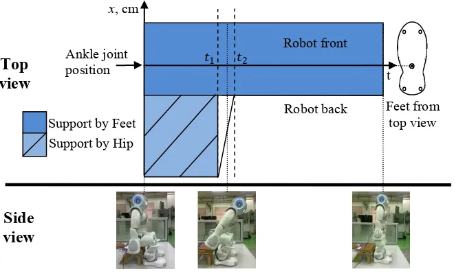
The main challenge in STS is addressing the robot’s lift-off from chair. The lift-off is a state when the hip that touches the chair’s surface starts to lift. System’s support polygon area becomes smaller since the feet are the only surface that is still in contact with the ground when the robot hips lift from the chair surface. The illustration of the lift-off is shown in Figure 1.1. The top part of the figure described the transition of the support polygon from the top view starting from the robot at sit position to standing. The period between 1 and 2 is nearly to zero where fast transition happened. The bottom part of the
3
Figure 1.1: Lift-off from chair occur between 1and 2.
In solving the problem, two main components of the humanoid STS motion system were observed; the (1) phase and trajectory planning and (2) control scheme. Both components have to be considered to ensure stable motions which in turn allow the robot to stand successfully.
4
synchronizing all the joints so that only a small amount of force acts on each joints (Pchelkin et al., 2010).
The second component is the control scheme which can be divided into two parts, (1) joint control and (2) stability control. The function of joint control is to reduce the error between the trajectory given to the robot and the actual trajectory produced by the robot on each joints. In stability control, the focus of the control scheme is to follow exactly the motion that has been planned while keeping the stability of the robot. A control scheme is also crucial in managing when and how a system should react to keep a stable motion.
The study will benefit many, not only those in the field of humanoid robot advancement but also its immediate applications such as experimental tool for medical STS studies in joint motion analysis, body trajectory, and chair design analysis.
1.2 Problem statement
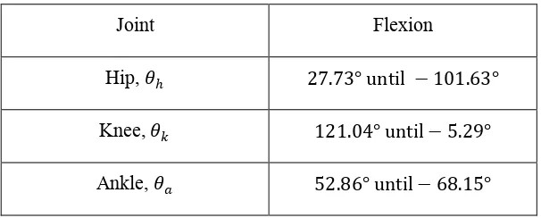
This section contains a detailed elaboration of the problem by using a NAO robot as the humanoid robot platform in the experiment. The robot is 0.573 high and has 25 degree of freedom. Focusing on lower body system, all joints are designed to be aligned to each other and the maximum flexion of each joint as in Table 1.1.
Table 1.1: Lower limb joint maximum flexion.
Joint Flexion
Hip, � 27.73° until −101.63°
Knee, � 121.04° until−5.29°
5
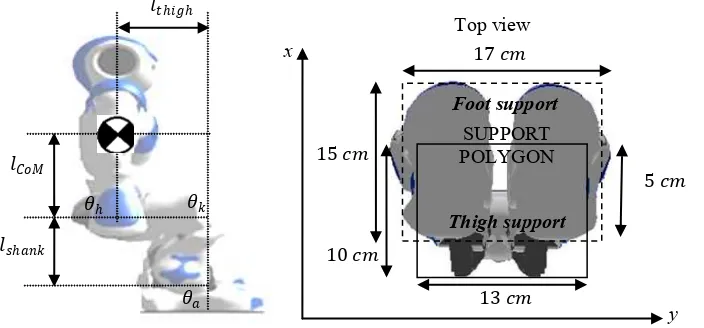
In order for any humanoid robot to maintain a stable upright position, its Centre of Mass (CoM) needs to be within an area called the support polygon (SP). Generally a support polygon (SP) is an area where ground in touch with any limb of the robot. However, at sitting position another support is provided by the chair that in touch with the thigh. Figure 1.2 shows the support polygon when the NAO robot is in a sitting position on the left figure and on the right is the view from bottom of the robot. At this position, the SP is an area of foot and thigh that contact with the ground and the chair surface respectively. In the head-arm-torso system (HAT), CoM is located at the centre of the robot’s body, where � = 15.0 as shown in Figure 1.2. = 10.0 is the length of the robot’s
thigh and the shank length represented by = 10.3 .
Figure 1.2: Position of Centre of Mass
When the robot thigh start to rise from the chair surface, the remaining SP is only area that support by the foot as mentioned in chapter 1.1.1 and illustrated in Figure 1.1. In order to ensure the HAT CoM always in the SP, proper trajectory planning is needed. The planning should consider on which joint and degree of flexion on each joint that should be controlled to prevent the robot from falling.
6
Apart from that, the trajectory planning must also able to consider the limitation of each joint flexion as mentioned in Table 1.1 and should operate automatically when the chair height is varied.
Thus, the research question is how to make a humanoid robot stand from a sitting position with its design limitations taken into consideration, with the assumption that there is no
external force acting on the robot?
Sit to stand motion also needs a control scheme after the lift-off to make sure CoM is always in the support polygon. Three joints (minimum) are needed for the NAO robot to stand but movements from these joints create disturbance that will disrupt the total velocity that is acting on the whole body. This disturbance is contributed by the change of direction in each joint during lift-off and causes imbalance by changing the CoM location from the SP.
The lift-off situation can be explained with an example of all joint being initially at; � = 90° for the knee joint, � =−75.6° for the hip joint and � =−7° for the ankle direction to anticlockwise. With all joint experiencing the same condition, an external momentum was generated. The momentum pushed the whole body of the subject to the front and may cause the subject to fall forward. The illustration of the lift-off problem is shown in Figure 1.1.