ISSN:1991-8178
Australian Journal of Basic and Applied Sciences
Journal home page: www.ajbasweb.com
Corresponding Author: Khalil Azha Mohd Annuar, Department of Electrical Engineering Technology, Faculty of Technology Engineering, Universiti Teknikal Malaysia Melaka, Hang Tuah Jaya, 76100 Durian Tunggal, Melaka, Malaysia.
E-mail: [email protected] Ph: 06-2346593
Thermal Analysis of Staggered Pin Fin Heat Sink for Central Processing Unit
1Khalil Azha Mohd Annuar, 1Mohamad Firdaus Mohd Ab Halim, 2Fatimah Sham Ismail, 1Madiha Zahari, 3Siti Halma Johari and 1Mohamad Haniff Harun
1
Department of Electrical Engineering Technology, Faculty of Technology Engineering, Universiti Teknikal Malaysia Melaka, Hang Tuah Jaya, 76100 Durian Tunggal, Melaka, Malaysia
2
Centre of Artificial Intelligence and Robotics, Faculty of Electrical Engineering, Universiti Teknologi Malaysia, 81310 Skudai, Johor, Malaysia
3
Department of Electronic & Computer Engineering Technology, Faculty of Technology Engineering, Universiti Teknikal Malaysia Melaka, Hang Tuah Jaya, 76100 Durian Tunggal, Melaka, Malaysia
A R T I C L E I N F O A B S T R A C T
The advancement of microelectronics technology in producing high clock speed and
power density’s central processor unit (CPU) indirectly related to thermal management issue. This is a major challenge to the manufacturers, designers and researchers to find the optimum design of the cooling system. If the problem is not being tackled, it will become a major setback to the development of electronic components and devices in the next five to ten years. The most popular technique used in the electronic devices is a metal heat sink with high heat transfer rate. The choice and suitable for the optimal heat sink design are needed in order to control and increase the heat dissipation. In this paper, 3D simulation staggered pin fin heat sink is designed and analyzed using COMSOL Multiphysics software. The finding of this study then is used to propose an optimal staggered pin fin arrangement of heat sink design that could give better thermal performance.
© 2015 AENSI Publisher All rights reserved. To Cite This Article: Khalil Azha Mohd Annuar, Mohamad Firdaus Mohd Ab Halim, Fatimah Sham Ismail, Madiha Zahari, Siti Halma Johari and Mohamad Haniff Harun., Thermal Analysis of Staggered Pin Fin Heat Sink for Central Processing Unit. Aust. J. Basic & Appl. Sci., 9(19): 68-73, 2015
INTRODUCTION
In embedded design, the most difficult
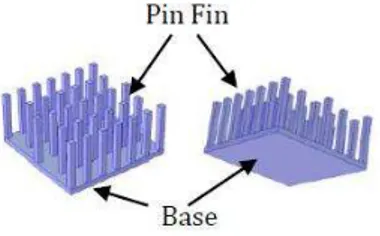
challenges to the semiconductor manufacturers are the demand to produce small package size, high speed and high power density CPU processor. There are many cooling techniques such as water cooling, heat pipes, liquid nitrogen and metal heat sink. The heat sink is one of the famous device that widely used as cooling technique in CPU processor unit due to its cost effective, simple and time consuming. The heat sink is a device that allows the transfer of heat away from the heat source (CPU). There are many designs in the market. But for the conventional heat sink model, it can be divided into two types, which are pin fin heat sink and plate fin heat sink.
There are many studies in the design of the heat sink model, especially in conventional arrangement plate fin and pin fin. A lot of questions by researchers and designers related to which type of heat sink that could give best in thermal performance. According to Kim et al. (2009), a comparison of the thermal performance between
two types of heat sink which are the plate fin and pin fin through an experiment. Various flow rates and width dimension have been used to find the thermal resistance performance. From the result, it is shown that pin fin model with lower heat source power dissipation will provide small thermal resistance. The plate fin model will produce small thermal resistance when the heat source power dissipated is high compared to pin fin type model.
simulation.
V.U. Patel and A.J. Modi (2012) study the heat transfer characteristics from fluid flow inside silicon
based micro channel heat sink by using
Computational Fluid Dynamic (CFD). This is a combination of conduction and convection heat transfer process by using water as a cooling fluid. This technique suitable for small component dimension and could gave optimal thermal problem solution when using micro channel heat sink model.
One of the most significant current discussions in power electronic system thermal management in three different types of heat sink which are extrusion fin, plain fin and cell fin. Lian-Tuu Yeh (2012) reported that by using CFD analysis to characterize each of the heat sink design. In recent years, several studies have focused on high power LED with different heat sink design. Fengze Hou et al. (2011) has demonstrated that thermal analysis of high of this paper was to study on the aerodynamic shape of cooling fins, to find the best method will reduce flow resistance of the heat sink. Kondo et al. (2000) studied zonal approach in optimizing the thermal performance of two types of heat sink with fix pumping power and dimension size. From the result shown, the optimal plate fin heat sink will produce 40% lower thermal resistance compared to pin fin type model heat sink. Based on the results presented from many studies in different type (Kim et al., 2009; Jonsson and Moshfegh, 2001; Zhou and Yang, 2008; Annuar et al. 2014; Kondo et al., 2000), mostly they concluded that the thermal performance of the pin fin heat sink will be given a better performance compared to plate fin model. However, the selection of these two types of heat sink is still not obvious.
Therefore, many researchers have been
conducted on the heat sink design has been executed in order to solve the thermal problem. There are many factors that affect the performance of the heat sink model design should be considered. The parameters are area, type of material used, airflow velocity and types of the heat sink shapes.
The aim of this study is to develop heat sink with the staggered arrangement of pin fin design by using COMSOL Multiphysics software package. The proposed heat sink models were tested on CPU Intel® Atom™ Processor N450. The simulation results, then proposed an optimal staggered pin fin that able to give better thermal performance compared to the conventional design. All the limitations values clearly are mentioned in this project.
Heat Transfer Equation:
The heat transfer is a part of dynamic process where heat or energy is transferred spontaneously from a hot area to the cool area. The rate of heat transfer is depending between two differences temperature areas. While the difference is increased, it will give high heat transfer rate. There are three types of heat transfer process, which are conduction, convection and radiation. In this study, COMSOL equation is described as equation (1).
(1) transfer (use airflow with heat sink) will allow high power processors to be cool in most of applications device. The equation for the air flow across the pin fin can be considered as follows:
(2)
Where n is the normal vector of the heat flux, h(Tamb-T) as known Newton law of cooling, which is used to specify the heat flux cause by forced (airflow) or natural convection process, and Tamb is ambient temperature. In this simulation, conduction and convection heat transfer are considered. Any other electronic components radiation effects such
as electromagnet heat dissipated by other
components near the CPU unit are not considered.
3D Heat Sink Model:
This study proposes 3D simulation, heat sink model with staggered pin fin arrangement using COMSOL Multiphysics software. The proposed heat
sink models were tested on CPU Intel® Atom™
Processor N450. The aluminium type of heat sink material is mounted on the top of the CPU processor chip. Various position pin fins of the heat sink are arranged in staggered.
the blower fan, heat sink design such as base, pin dimension and total number of pin, power dissipated from the chip and chip dimension.
The operating condition and model parameter
values for pin fin heat sink model are listed in Table 1. Figure 1 shows 3D staggered pin fin heat sink model.
Fig. 1: Example heat sink with staggered pin fin arrangement.
Table 1: Operation Condition and Model Parameter Values for Staggered Pin Fin Heat Sink Model.
Parameter Values
Air box Channel Length 6 cm
Width 5 cm
Height 2 cm
CPU
Length 2.2 cm
Height 0.1 cm
Power dissipated 5.5 W
Pin fin
Height 1.7 cm
Diameter 0.2 cm
Number of pin 36
Heat sink base Base thickness 0.2 cm
Diameter 4 cm
Air flow inlet Inlet velocity 10 cm/s
Inlet temperature 20 °C
Material Aluminium
a) Geometry of Heat Sink:
Geometrical pin fin of the heat sink model is drawn using COMSOL Multiphysics software. Another alternative way, it is also can be drawn and imported from another software tools such as CAD, Solid Works and others similar type software (.mphbin file).
Figure 2 shows that the heat sink model can be divided into two parts, which is the heat sink base and square pin fins. The heat sink base dimension is fixed to the width, depth and height. The total number of square pin fin selected in this simulation is 36 fins with various staggered positions on the heat sink base.
Fig. 2: Example of heat sink geometry.
b) Model Building:
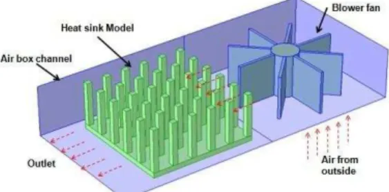
The heat sink is modelled by finite element method using the software package COMSOL Multiphysics under conjugate heat transfer interface module. This module provides a necessary tool to do the analysis the heat sink model under conduction and convection heat transfer. All other properties and parameter related are set by the user as shown in table 1.
Fig. 3: Actual process for experimental setup with blower.
c) Staggered Arrangement of Pin Fin:
There are about 25 models with a different position or design in staggered arrangement of pin
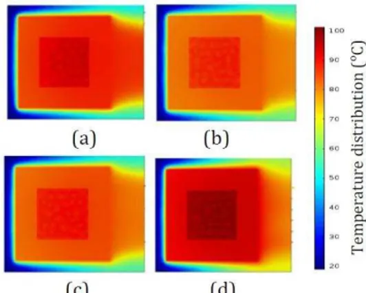
fin heat sink model were tested. Selected four (out of 25 models) staggered position pin fin of heat sink model are shown in Figure 4.
Fig. 4: Example staggered pin fin arrangement design.
Simulation Result & Discussion:
The simulation is done using COMSOL Multiphysics under Conjugate Heat Transfer Interface on a desktop computer equipped with 12 GB RAM and Intel i3-2120 3.30 GHz processor. The best thermal performance produced for this model is 88.83ᵒC shown as Figure 5(b). Figure 6 shows the bottom view temperature distribution for chip processor.
From the result we can observe that different arrangement of pin fin mounted on the base heat sink will give a different thermal performance
temperature even though total amount area and volume of each model are similar. These results show that good heat thermal performances depend on the geometry and position of the pin fin in order to create smooth air flowing on the surface of the pin fins heat sink.
Most of the staggered design will create turbulence airflow around the pin fin on the base heat sink. It can be seen in figure 7 (c), which can increase heat dissipated far away from the heat sink. However, for figure 7 (a) turbulence flow has increased the heat around the pin.
Fig. 6: Bottom view plot of temperature on chip and base of heat sink.
Fig. 7: Top view plot of temperature and airflow.
Conclusions:
This paper has presented thermal performance of various staggered pin fin heat sink design for the CPU processor. The heat transfer phenomena of the various staggered pin fin arrangements are investigated using COMSOL Multiphysics software. Based on the 3D simulation result thermal profile, we can analysed the output thermal performance of the heat sink. Simulation results showed that different design or position of pin fin arrangement will give different heat distribution. Model B design, staggered pin fin heat sink will give better performance which is 88.83ᵒC. The result states that the importance of choosing the suitable arrangement of pin fin as it gives better thermal performance for the CPU processor. Also by knowing the best performance pin fin heat sink will be increase and maintain the performance of the component. For future work can be use by using population based evolutionary algorithm optimization method in finding an optimal arrangement of pin fin.
ACKNOWLEDGMENT
The authors would like to thank for the support given to this research by Ministry of Education Malaysia and Universiti Teknikal Malaysia Melaka (UTeM) under PJP/2014/FTK(3B)/S01302 project.
REFERENCES
Kim, D.K., J.K. Bae and S.J. Kim, 2009. Comparison of Thermal Performances of Plate-Fin and Pin-Fin Heat Sinks Subject To An Impinging Flow. International Journal of Heat and Mass Transfer, 3510-3517.
Chen, C.T. and S.H. Jan, 2012. Dynamic Simulation, Optimal Design and Control of Pin-fin Heat Sink Processes. Journal of the Taiwan Institute of Chemical Engineers, 43: 77-88.
Patel, V.U. and A.J. Modi, 2012. Optimization of Heat Sink Analysis for Electronics Cooling. Proceedings of A National Conference on Advances in Mechanical Engineering (NCAME-2012). 64-69.
Lian-Tuu Yeh, 2012. Thermal Performance Evaluation of Various Heat Sinks for Air Cooling. Thermal and Thermomechanical Phenomena in Electronic Systems (ITherm), 13th IEEE Intersociety Conference, pp: 446- 449.
Fengze Hou, Daoguo Yang, G.Q. Zhang, Yang Hai, Dongjing Liu and Lei Liu, 2011. Thermal Transient Analysis of LED Array System with In-line Pin Fin Heat Sink. Thermal, Mechanical and Multi-Physics Simulation and Experiments in Microelectronics and Microsystems (EuroSimE), 12th International Conference pp: 1-5.
Behaviour of High Power LED. Quality Electronic Design (ASQED), 3rd Asia Symposium, pp: 21-24.
Hofinger, D., M. Jungwirth, H. Pflugelmeier and A. Eder, 2011. Heat Sink Design for Optimal Thermal Management. Thermal, Mechanical and
Multi-Physics Simulation and Experiments in
Microelectronics and Microsystems (EuroSimE), 12th International Conference, pp: 1-4.
Annuar, K.A.M. and F.S. Ismail, 2014. Optimal Pin Fin Arrangement of Heat Sink Design and Thermal Analysis for Central Processing Unit. Intelligent and Advanced Systems (ICIAS), 5th International Conference, pp: 1-5.
Zhou, J.H. and C.X. Yang, 2008. Design and Simulation of the CPU Fan and Heat Sinks. Components and Packaging Technologies, IEEE Transactions, pp: 890-903.
Kondo, Y., H. Matsushima and T. Komatsu, 2000. Optimization of Pin-Fin Heat Sinks for Impingement Cooling of Electronic Packages. J. Electronic Packaging, 122.