UNIVERSITI TEKNIKAL MALAYSIA MELAKA
THE APPLICATION OF C- SHAPED CURVE IN AIR FILTER
DESIGN: A CASE OF PERFORMANCE CAR
This report submitted in accordance with requirement of the Universiti Teknikal Malaysia Melaka (UTeM) for the Bachelor Degree of Manufacturing Engineering
(Manufacturing Design) with Honours.
By
JULIA ANAK LUMING B051110295 910410-13-5964
THE APPLICATION OF C-SHAPED CURVE IN AIR
FILTER DESIGN: A CASE OF PERFORMANCE CAR
JULIA ANAK LUMING
B051110295
UNIVERSITI TEKNIKAL MALAYSIA MELAKA
UNIVERSITI TEKNIKAL MALAYSIA MELAKA
BORANG PENGESAHAN STATUS LAPORAN PROJEK SARJANA MUDA
TAJUK: THE APPLICATION OF C-SHAPED CURVE IN AIR FILTER DESIGN
: A CASE OF PERFORMANCE CAR
SESI PENGAJIAN: 2014/2015 SEMESTER 2
Saya JULIA ANAK LUMING
mengaku membenarkan Laporan PSM ini disimpan di Perpustakaan Universiti Teknikal Malaysia Melaka (UTeM) dengan syarat-syarat kegunaan seperti berikut:
1. Laporan PSM adalah hak milik Universiti Teknikal Malaysia Melaka dan penulis. 2. Perpustakaan Universiti Teknikal Malaysia Melaka dibenarkan membuat salinan
untuk tujuan pengajian sahaja dengan izin penulis.
3. Perpustakaan dibenarkan membuat salinan laporan PSM ini sebagai bahan pertukaran antara institusi pengajian tinggi.
DECLARATION
I hereby, declared this report entitled “The Application of C- Shaped Curve in Air Filter Design: A Case of Performance Car” is the results of my own research except as cited in references.
Signature : ……….
Author’s Name : ………
APPROVAL
This report is submitted to the Faculty of Manufacturing Engineering of UTeM as a partial fulfillment of the requirements for the degree of Bachelor of Manufacturing Engineering (Manufacturing Process) with Honours. The member of the supervisory committee is as follow:
………
(Supervisor)
………
ABSTRAK
Secara teorinya, prestasi penapis udara adalah mengikut rekabentuk penapis udara, saiz penapis udara dan jenis bahan yang digunakan. Rekabentuk penapis udara dipilih sebagai kanta dalam kajian penyelidikan ini. Rekabentuk kon seperti Rezton dipilih sebagai rekabentuk yang sedia ada kerana prestasi dan rekabentuk yang sama jika dibandingkan dengan rekabentuk penambahbaikan. Prestasi penapis kon mengikut rekabentuk corong, sudut batang dan dimensi batang. Oleh itu, ciri-ciri ini diperlukan apabila merekabentuk penapis kon ini. Konsep berbentuk C peralihan keluk atau juga dikenali sebagai keluk berprofil tinggi kemudian dicadangkan untuk mengatasi masalah ini. SolidWorks adalah perisian yang digunakan dalam merekabentuk profil penapis udara sama ada secara sedia ada atau model rekabentuk penambahbaikan. Skim-skim struktur linear statik dan analisis “fatigue” digunakan untuk mengetahui kesesuaian struktur antara model dalam mod statik. Hasil ini menunjukkan bahawa apabila maksimum Von Mises tekanan dan anjakan adalah lebih rendah, justeru itu, nilai baik faktor keselamatan dapat dicapai. Selain itu, COMSOL Multiphysics 4.2a adalah pakej dinamik yang digunakan untuk menganalisis model-model dalam tujuan dinamik. Daripada hasil kajian ini, bagi input halaju yang sama
iaitu 6
ms
-1, halaju, tekanan dan kelikatan untuk rekabentuk penambahbaikan adalahABSTRACT
Theoretically, the performance air filter is in accordance to the shape design of air filter, the size of the air filter and the type of material used. The shape design of the air filter is selected as a lens on this research study. The conical design such as Rezton is chosen as an existing design due to its performance and similar design when compared to the improvement design. The performance of conical filter is mostly considered the design of the funnel, an angle of stem and the dimensions of stem. Thus, these characteristics are required when designing this conical filter. The concept of C-shaped transition curve or also known as high profile curve is then proposed to overcome this issue. SolidWorks is the software used in designing the air filter profile either in existing or in improvement design models. The structural schemes such as linear static and fatigue analyses are applied to find out the structural applicability amongst the models in static mode. The resulted showed that when the Maximum Von Mises Stress and displacement are lower, consequently, the good value of safety factor is achieved. Furthermore, the COMSOL Multiphysics 4.2a is the dynamic package that used to analyze the models in dynamic
purposes. As the results, for the same input velocity where initial velocity is 6
ms
-1, thevelocity, pressure and viscosity for improvement design are 82.152
ms
-1, 7848.8 Pa andDEDICATION
Specially dedicated to my father, Luming anak Giman and my mother. Sidot anak Andum who are very understanding, caring, patient and supporting for help me mentally. Also thanks to my dearest siblings, honorable lecturers and loyal friends for
ACKNOWLEDGEMENT
5.1.2 Creating the geometry in Model Builder for
COMSOL Multiphysics (Single Flow) 77
5.1.3 Turbulent Flow Defined in COMSOL Multiphysics 79
5.1.4 The Meshing Process of the Models 84
5.2 Velocity, Pressure and Viscosity amongst the Models 86
5.3 Coefficient of Variation of the Models 92
5.3.1 Coefficient Variation for Velocity 93
5.3.2 Coefficient Variation for Pressure 95
5.4 Conclusion 96
CHAPTER 6: CONCLUSION AND RECOMMENDATION 97
6.1 Conclusion 97
6.2 Recommendation 98
REFERENCES 100
LIST OF TABLES
4.1 The mesh information of existing and improvement designs 55
4.2 The properties of AISI 304 Stainless Steel 59
4.3 Stress and displacement results for existing and improvement designs 63
4.4 The results of stress and safety factor for both designs 65
4.5 The pressure applied and safety factor of both designs 68
4.6 Divided difference for newton interpolation polynomial for existing design 68
4.7 The initial pressure for both designs 69
5.1 Physical Properties of Air 78
5.2 The elements and minimum element quality of amongst the models 85
5.3 The results obtained using COMSOL MultiPhysics 4.2a 89
5.4 Statistical analysis in the design models (velocity) 93
LIST OF FIGURES
2.10 S-shaped transition curve 22
3.3 The process flow diagram of air filter’s profile design using
C-shaped transition curve 33
3.4 The 2D sketching (left) and 3D design model (right) of air filter’s
profile using C-shaped transition curve 34
3.5 The process flow diagram of 2D sketch and 3D design
model high performance air filter (REZTON) 35
3.6 The 2D sketching (left) and 3D design model (right) of the
REZTON air filter 36
3.7 The example TET10 elements in piston 37
3.8 The process flow diagram of linear static analysis for the design
models using SolidWorks software 39
3.9 The process flow diagram of fatigue analysis for existing and
improvement models 41
3.11 The overall flow diagram of the simulation process using
COMSOL Multiphysics 4.2a 44
3.12 The process flow diagram of dynamic analysis using COMSOL Multiphysics 4.2a 46
4.8 The loading condition on the existing (left) and improvement design (right) 58
5.5 Boundary condition surface for outlet of existing design (left) and
improvement design (right) 83 5.6 The meshing process in existing (left) and improvement (right) designs 85 5.7 Velocity volume for existing (above) and improvement (below) design at
-5.8 velocity streamlines for existing (above) and improvement (below)
design at v =6ms-1
i 87
5.9 Pressure contour for existing (above) and improvement (below) design atv =6ms-1
i 88
5.10 Wall resolution viscosity for existing (above) and improvement (below) designv =6ms-1
i 88
5.3 The equation of Reynolds number 80
5.4 The equation of inlet boundary condition 82
5.5 The equation of outlet boundary condition 83
5.6 The equation of Bernoulli’s Principle 92
LIST OF ABBREVIATIONS, SYMBOLS AND
OEM - Original Equipment Manufacturer
CFD - Computational Fluid Dynamics
CAGD - Computer Aided Geometric Design
CAD - Computer-Aided Design
FEA - Finite Element Analysis
FEM - Finite Element Method
2D - Two Dimensional
3D - Three Dimensional
FEA - Finite Element Analysis
CHAPTER 1
INTRODUCTION
The Chapter 1 focuses on the general ideas of the research study, which provided an overview of the air filter profile design using C shaped curve. In this chapter, it consists of the background of the project, problem statements, objectives and the scope of the research study.
1.1 Background of the Research Study
Air is not only vital in any life form on earth, but also the important mechanism in vehicles especially the performance of the car engine. Nonetheless, air is constantly contaminated with all sorts of pollutants such as fumes, dust, smoke and other atoms. For example, temperature and humidity, these particles are not always visible to the eye, but they are harmful to the engine. Chander et al. (2014) observes that these particles reduced the cleanliness of the air and can lead to severe damage of all engine components.
Basically, Julian (2011) stated that the air filter is an essential part of a car's intake system, as it is through the air filter that the engine "breathes". In addition, Julian (2011) also explained that the purpose of the air filter is to filter out dirt and other foreign particles in the air and improving the combustion efficiency. While an air filter is one of the essential components of engines as defined by Shukri et al. (2013).
material used. Therefore, the shape design of air filter is selected as the lens for this research study.
In general, profiles define as the surface elevation along an alignment. Profile design is important in designing the air filter because the profile design will affect the efficiency of an air filter performance (Bugli et al., 2004). According to Michael et al. (2000), it is impossible to maintain good air quality with a poorly designed of an air filter. This statement also supported by Julian (2011) that the poor air quality will significantly impact the performance of a car engine.
Nowadays, there are several types of air filter such as panel filter, cylindrical filter and conical filter. In general, the method designing of panel air filter was using rectangular shape. Mathematically, the volume of a rectangle is increased in contrast to its density is low. Therefore, the pressure loss in the air filter is low due to low air density. Generally, the air filter panel was designed to have a high cleaning efficiency, but it shows that pressure drop is low (Farr, 1940). Figure 1.1 shows the panel of the air filter.
Figure 1.1: Panel air filter (Anonymous, 2014)
the filter axially through a central opening of the filter (Sundquist, 1998). Mathematically, the density of the cylinder is low due to its volume is high. Figure 1.2 represents the cylindrical of air the filter.
Figure 1.2: Cylindrical air filter (Anonymous, 2014)
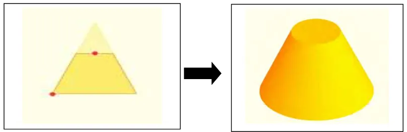
Moreover, the cone air filter was designed by using the cone method. Beyer (1987) said that the conical design is created by cutting the top off a cone (with the cut made parallel to the base) that displayed in Figure 1.3.
Figure 1.3: The slicing top off a cone (left) and final conical design (right) (Beyer, 1987)
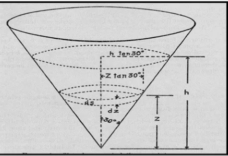
Figure 1.4: Cone and its application in conical filter (Bogaty and Carson, 1944)
The example of conical air filter such as Rezton’s air filter. Rezton’s air filter has applied cone as a basis model of designing it. According to Tadeusz et al. (2004), the pressure loss coefficient of the conical filter elements is higher than another type of the shape design while the air velocity is also increased. Figure 1.5 shows the Rezton’s air filter.
Figure 1.5: Conical air filter (Anonymous, 2014)