UNIVERSITI TEKNIKAL MALAYSIA MELAKA
MANUFACTURING, ASSEMBLY AND TRIAL OF CORE AND
CAVITY PLASTIC INJECTION MOULD FOR TWO-PLATE
FAMILY MOULD TESTING SPECIMENS
This report submitted in accordance with requirement of the Universiti Teknikal Malaysia Melaka (UTeM) for the Bachelor Degree of Manufacturing Engineering
Faculty of Manufacturing Process (Hons.)
by
KHAIRUL ANWAR ADHWA BIN MOHAMAD KASIM B051110340
870707135523
DECLARATION
I hereby, declare this report entitle “Manufacturing, Assembly and Trial of Core Plastic Injection Mould for Two-Plate Family Mould Testing Specimens” is the result of my own
research except as cited in the reference
Signature :………..
Author’s Name :………..
APPROVAL
This report is submitted to the Faculty of Manufacturing Engineering of UTeM as a partial fulfilment of the requirement for the degree of Bachelor of Manufacturing Engineering (Process) (Hons.). The member of the supervisory is as follow:
i
ABSTRAK
Projek ini dijalankan dengan tujuan untuk memahami proses mereka bentuk dan memesin plat acuan core dan cavity untuk dua plat family mould. Tujuan utama projek ini ada untuk menambah baik acuan lama dengan mereka bentuk dan fabrikasi dua plat family mould yang mengandungi empat bahan ujian iaitu tensile, flexural, impact, dan hardness. Kaedah pemesinan utama yang digunakan adalah CNC Milling
dan mesin yang digunakan adalah model Hass VF-1 yang terdapat di makmal pembuatan UTeM. Proses mereka bentuk dibuat dengan menggunakan bantuan perisian AutoCAD di mana ia menghasilkan lukisan kejuruteraan dua dimensi (2D) untuk acuan tersebut. Dengan menggunakan perisian EdgeCAM, lukisan 2D tadi di ubah menjadi tiga dimensi (3D) dan program arahan untuk mesin turut di hasilkan untuk di hantar kepada mesin untuk proses fabrikasi. Proses fabrikasi dimulakan dengan menebuk lubang untuk pin ejector, pembentukan profile bahan ujian, dan
ii
ABSTRACT
iii
DEDICATION
To my beloved parent, Mohamad Kasim Bin Arbain and Hasipah Binti Siri, my lovely sibling Khuwailid Ridha Bin Mohamad Kasim, Khamiludeen Redhwa Bin Mohamad Kasim and my only beautiful sister, Khairuneeza Nur Alia Binti Mohamad
Kasim, and all my loyal friend, all of tour love and prayer are my driving source and your guidance is enlightment to me.
iv
ACKNOWLEDGEMENT
Bismillahirrahmanirrahim
In the name of Allah, the most gracious and the most merciful,
Alhamdulillah and praise to Allah S.W.T. for the bless and enlightment that given to me to complete my Final Year Project (FYP) from the beginning of my step until end of my journey. The journey was hectic and full of challenges but Alhamdulillah every problems faced, has the solution thank, than to Allah, and everyone that help me all the way. First of all, an infinite thanks for Dr. Mohd Amran Bin Md. Ali, my supervisor for the guidance all the way in making this project a successful project. He has been my major enthusiast and reference for this project.
v
1.1Background of Project 1
1.2Problem Statement 2
1.3Objective of Project 3
1.4Scope 3
1.5Organization of the Report 3
CHAPTER 2: LITERATURE REVIEW
2.1 Injection Moulding 5
vi
2.7 Machining Process 14
2.7.1 Milling 14
2.7.1.1 Face Milling 14
2.7.1.2 End Milling 15
2.7.2 Drilling 15
2.8 Molten Material 15
2.8.1 Polypropylene (PP) 15
2.9 Product Defect 16
2.10 Summary 17
CHAPTER 3: METHODOLOGY
3.1 Introduction 18
3.2 Discussion and Conformation of the Project Title 20
3.3 Project Introduction 20
3.4 Literature Review 20
3.5 Designing the Mould 20
3.5.1 Predesign Concept 21
3.5.2 Designing the Core and Cavity Plate 21
3.5.2.1 Brainstorming Idea 21
3.5.2.2 Screening and Scoring 21
3.5.2.3 Concept Design Development 22
3.5.3 Detail Design 22
3.6 Mould Trial 25
3.7 Analyse and Data Collection 25
3.8 Material Selection 26
3.8.1 Core and Cavity Plate 26
vii CHAPTER 4 RESULT AND DISCUSSION
4.1 Design 28
4.2 Core and Cavity 28
4.2.1 Core Plate 28
4.2.2 Cavity Plate 29
4.3 Material Preparation 30
4.4 Machining Procedure 30
4.4.1 Process Planning 31
4.4.2 G-Code 32
4.4.3 CNC Milling 32
4.5 Mould Assembly 34
4.6 Injection Moulding Process 36
4.7 Product 38
CHAPTER 5 CONCLUSION AND RECOMMENDATION
5.1 Conclusion 40
5.1.1 Manufacturing, Assembly and Testing 40
5.1.2 Product Defect 40
5.2 Recommendation 41
5.2.1 Secondary Process 41
5.2.2 Marking 41
REFERENCES 42
APPENDICES
A Gantt Chart for PSM I B Gantt Chart for PSM II
viii F AutoCAD Drawing of Ejector Plate
ix
LIST OF TABLE
2.1 Mechanical Property of Mild Steel 8
2.2 Moulding Defect 16
4.1 Core Plate Checklist 31
x
LIST OF FIGURE
2.1 Schematic diagram of plastic injection moulding machine 6
2.2 Basic Mould Base 7
3.2 Process Flow Chart in Designing Mould 23
3.3 2-D AutoCAD design of the two-plate family mould core 24 3.4 2-D AutoCAD design of the two-plate family mould cavity 24
3.5 2-D AutoCAD design of expected product 25
4.4 Machining process in progress 33
4.5 Complete machining of the core plate 34
4.6 Cavity plate assemble with its base 35
4.7 Core plate assemble with its base 35
xi 4.11 The core plate and base clamped in assembly area 38 4.12 The product at the core plate before ejected 39
xii
LIST OF ABBERVATIONS, SYMBOLE AND
NOMENCALTURE
ASMT - American Society for Testing and Materials CAD - Computer-Aided Design
CAM - Computer-Aided Manufacturing
CATIA - Computer Aided Three-dimensional Interactive Application CNC - Computer Numerical Control
EDM - Electric Discharge Machine G-Code - Programming language HDPE - High-density polyethylene
HSS - High Speed Steel
PP - Polypropylene
1
CHAPTER 1
INTRODUCTION
This chapter includes the introduction of the background of project for manufacturing the two-plate injection mould, the problem statement of the project, its main objective that should be archived and the project scope.
1.1 Background of Project
Injection moulding is one of the near nett process machining where little amount of secondary process is involve. Usually this process will produce excess of runner where the molten material such as molten polymer is injected into the mould to form desire shape. Ghosh (2011), stated thatthis process is subjected to high pressure so that the melted thermoplastic is injected by plunger action with the help of plunger system. The material is first heated in a heating barrel where it is molten and mixed with additive such as colouring before the molten material is compress and forced into the mould by the ejector through the mould cavity and the molten material is let to cool off and harden before ejected from the mould. Injection moulding is commonly used in the manufacturing industries where it can produce a variety of product from the smallest part such as plastic nut and bold, to the largest parts such as car dashboard.
2 desire where the mould is first design with CAD software and the detailing is studied to overcome the machining problem and could produce the desire output. Thus, a proper research and study should be conducted to produce the optimum output can be archived.
There a several type of injection moulding mould available in the industries and in this case study a family moulding is conducted to study the design of the family moulding mould. Family mould is a mould where the mould consist more than one product design in the injection mould plate.
1.2 Problem Statement
3 1.3 Objective of Project
There are several sub-objective should be archived in this project such as:
i. To design a mould that consist four testing design, that is dumbbell shape for tensile test, coin shape for hardness test, plate shape for flexural test, and plate with notch for impact test.
ii. To machine the mould with CNC to produce the four shape required. iii. To assemble the mould cavity and core plate to the mould base with ease. iv. To run trial for the mould and produce all of the testing product.
1.4 Scope
This project focus is on redesign and fabricate the existing two-plate family mould of two tensile specimens into the new mould plate that consist 4 test specimens of tensile, flexural, hardness, and impact test. The design of the mould will be visualized by using AutoCAD software where the dimension of the test specimen is gather from the ASTM standard for test specimen. The main machining process to fabricate this mould is CNC milling and the G-Code is generated by using EdgeCAM software. The final stage of this project is to ensure the mould plate could be fitted to the base plate with ease.
1.5 Organization of the Report
To ensure the objective of this project is archived, there are 5 segment that consist in this project.
1. Chapter 1 explain the introduction of the report. This chapter include background, problem statement, objectives and project scopes.
4 3. Chapter 3 discuss the methodology. It cover all the procedure and
progress of the project from start until end including using software and machining process that involve during the project.
4. Chapter 4 display the result and discussion of the project and explain the comparison of results.
5
CHAPTER 2
LITERATURE REVIEW
This chapter presents of review the theories involved in this project beside describe the basic of injection moulding process. Beside that the machining is be explained alongside the designing step of the mould, type of mould and its material and the machining process that involved in this mould fabrication.
2.1 Injection Moulding
Injection moulding is a process where high pressure molten plastic is injected into a mould cavity which will forced the molten plastic to fill the negative part of the product on the cavity thus producing the complete positive component. Injection pressure usually measure in pound per square inch (psi) unit. The mould need to be securely clamp due to high pressure from the injector.
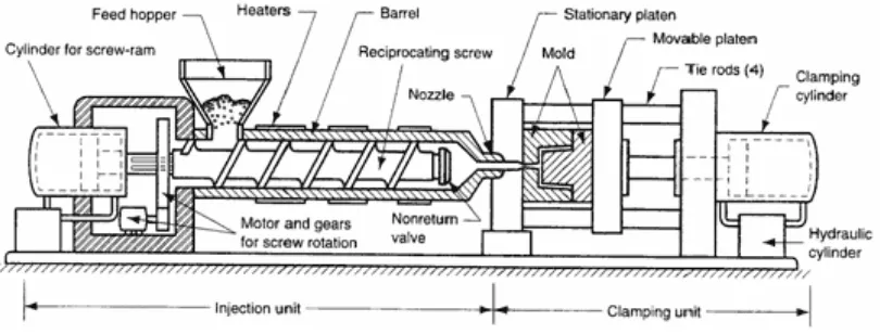
Plastic injection moulding machines composed of three components such as the injection unit, the clamping unit and the control system. In the injection unit section, it will melt and injects the polymer. At the same time, the clamping unit supports the mould, opens and closes the mould and clamping unit also has the part ejection system. By using the same clamping unit, different injection unit also can be assembled Harper (2000).
6 precisely controlled to produce high quality product with minimal possible cost. Besides, the process is very fast where it take less than a minute to complete a full cycle of the manufacturing process. By locating multiple cavity image on the mould, the output may increase at the same time (Bryce, 1998). The schematic diagram of plastic injection machine is shown in Figure 2.1.
Figure 2.1 Schematic diagram of plastic injection moulding machine.
(http://www.xcentricmold.com/aboutinjectmold.php)
Rosato (2003), state that the mould design is determine by product design and requirement. Some mould are built with standard parts and use different core and cavity insert so that the cost can be minimized in manufacturing many variant design of product. Many cavity may be provided in mould to reduce the cost while maintaining the production rate output. Thus, the more cavity produce in a mould, the more complex the moulds will be.
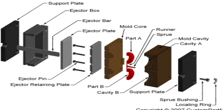
2.2 Mould Base
7
Figure 2.2: Basic Mould Base (CustomPartNet, 2007)
The machinery capacity requirement and the number of cavities in the mould are limited by its size and weight of parts to be moulded. Large clearance between the machines tie-rods are required corresponded to large exterior dimension of a single-cavity mould in the fabrication of large moulding parts. The number of single-cavity in multi-cavity mould are limited by the machine tie-rod clearance.
A mould has to be designed with capability to absorb the forces of clamping, injection, and ejection safely. Moreover, for obtaining the uniformity of product quality in continuous production cycles, the flow conditions of the plastic path had to be proportioned acceptably. The mould has to be able to absorb the heat from the plastic effectively while the solidification of the plastic product must be at controlled rate (Rosato, 2003).
2.3 Mould Material
8 classified into vary of type according to its chemical composition, heat treatment method, mechanical properties, thermal properties, surface finishing and many more.
The mould material usually focus on two main parts that is base plate, and core & cavity plate. The variation of material that available on the industries can provide many type of mould based on custom requirements that provide custom desired properties. For this mould, Plastic Injection Moulding Volume 3(Bryce, 1998) is used as reference and guideline to determine what type of material should be choose to fabricate the mould.
2.3.1 Mild Steel
The most common form of steel because its price is relatively low while it provides material properties that are acceptable for many applications, more so than iron. Low-carbon steel contains approximately 0.05–0.320% carbon making it malleable and ductile. Mild steel has a relatively low tensile strength, but it is cheap and malleable; surface hardness can be increased through carburizing
2.4 Mould Material Properties
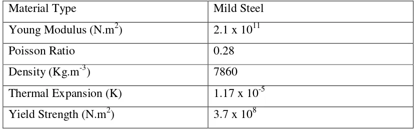
Below are the mechanical properties of Mild steel.
Table 2.1: Mechanical properties of Mild steel
Material Type Mild Steel
Young Modulus (N.m2) 2.1 x 10¹¹
Poisson Ratio 0.28
Density (Kg.m-3) 7860
9
2.5 Type of Mould
In industries there are many demand and consideration upon producing plastic product that required different type of mould. Generally there are six types of injection mould that available for plastic injection that is two-plate mould, three-plate mould, hot-runner mould, insulted hot-runner mould and stacked mould. Greener and Wimberger Friedl (2006), has provide the detail of the mould types for further study and review.
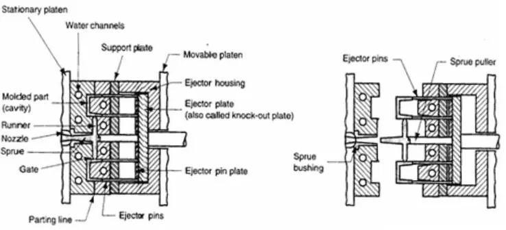
2.5.1 Two Plate Mould
This is the most common and basic type of injection mould that is selected for this project of family mould. This mould contain two-plate mould section where the core and cavity are mounted on either plate and it is fastened and secured to the press platens. Mould can contain a single cavity or multiple cavities to produce one or many part in a single shot. Figure 2.3 below shows the two-plate mould.
Figure 2.3 Two-plate mould (http://www.sinotech.com/injectionMolded.html)