UNIVERSITI TEKNIKAL MALAYSIA MELAKA
DESIGN VALIDATION AND
DEVELOPMENT OF PLASTIC
INJECTION MOULD CAVITY FOR
CONTAINER PLASTIC PRODUCT
Thesis submitted in accordance with the partial requirements of the
Universiti Teknikal Malaysia Melaka for the
Bachelor of Manufacturing Engineering (Manufacturing Design)
By
CHIN KAT MENG
ii
DECLARATION
I hereby, declare this thesis entitled “Design Validation and Development of Plastic Injection Mould Cavity for Container Plastic Product” is the results of my own
research except as cited in the reference.
Signature : ………
Author’s Name : CHIN KAT MENG
iii
APPROVAL
The thesis submitted to the senate of UTeM has been accepted as partial
fulfillment of the requirement for the degree of Bachelor of Manufacturing
Engineering (Manufacturing Design). The members of the supervisory
committee are as follows:
……… Main Supervisor: Mr. Hassan Attan
Date : ………..
iv
ABSTRACT
Plastic Injection Moulding is one of the popular commercial manufacturing in plastic industry, it has the ability to produce any complex design product. This project, aims to validate design of the plastic container to be manufactured by using plastic injection molding. The design of the product needs to convert into cavity and core of the mould and the form of mould cavity is done by using several advanced manufacturing processes to fabricate the product.
This project begins with the validation of the dimension of the mould by measuring the existing mould using CMM machine. The procedures of handling mould and the method to measure the mould dimension will be state out. The next step is modeled process using CAD/CAM software to construct the 3D model. The CAD/CAM software used in this modeling process is CATIA, because it has wide flexibility and capabilities in the 3D modeling. After the modeling, a process plan is generated and the mould fabrication processes will be carried out using various type of manufacturing process. The design feature and process parameter is analyzed and verified.
ABSTRAK
‘Plastic Injection Moulding’ adalah salah satu proses pembuatan komersial yang popular dalam perindustrian plastik, ia dapat menghasilkan pelbagai jenis produk rekabentuk kompleks. Projek ini, bertujuan untuk mengesahkan rekebentuk kotak plastik yang digunakan dalam mesin suntikan plastik. Rekabentuk plastik produk itu perlu ditukar dalam bentuk acuan dengan menggunakan beberapa jenis proses pembuatan termaju untuk menghasilkan produk ini.
Projek ini dimulakan dengan mengesahkan ukuran acuan dengan menggunakan mesin CMM. Seterusnya ialah menunjukkan langkan-langkah untuk menguruskan acuan dan cara-cara untuk mengukur ukuran acuan itu. Permodelan 3D akan menggunakan perisian CAD / CAM sebagai satu alat model untuk membina 3D model. Perisian CAD / CAM yang akan digunakan dalam proses permodelan 3D adalah CATIA, kerana ia mempunyai fleksibiliti yang luas dalam permodelan 3D. Selepas permodelan 3D, menghasilkan suatu proses rancangan dan proses fabrikasi acuan akan mengikut rancangan yang ditentukan. Fabrikasi acuan akan dijalankan dengan menggunakan berbeza jenis mesin dan proses.
vi
ACKNOWLEDGEMENT
First and foremost, I would like to express my thousand of thanks to my honorable supervisor, Mr. Hassan Attan, for this endless support and help throughout this project. Through his invaluable guidance and advice, this project has become a
vii
List of Abbreviations ...xvii
1. INTRODUCTION ...1
1.1 Background of the Problem ...2
1.2 Statement of the Problem ...2
1.3 Objectives ...3
1.4 Scope ...3
1.5 Importance of the Project ...3
1.6 Organization of the Report ...4
1.7 Flow Chart of the Project ...6
1.8 Schedule of the project ...6
1.9 Summary ...7
2. LITERATURE REVIEW ...8
2.1 Introduction ...8
2.2 Mould Development Process ...8
2.3 Mould Design ...14
2.3.1 Number of cavities and Surfaces Finish ...17
2.4 Introduction of Mould ...19
viii
2.4.1.1 Sprue and runner system ...21
2.4.1.2 Cavity Layout ...24
2.4.1.3 Parting Line ...24
3.2 Material Selection for Mould Cavity ...27
3.3 Measure the Dimension of the Mould ...29
3.3.1 Release Mould from the Machine ...29
3.3.2 Open Mould to separate core and cavity side ...31
3.3.3 Mould Structure of Plastic Container ...32
3.3.4 Meas ure the Mould Cavit y B y Using CMM and Digital Calipers ...34
3.3.4.1 Coordinate Measuring Machine ...34
3.3.4.2 Vernier Caliper ...39
3.4 Design Validation 3 . 3 . 1 D i f f e r e n t i a t e D i m e n s i o n b e t w e e n m e a s u r i n g original mould and measuring product ...44
3.5 Part Modeling ...46
3.5.1 3D MODELING SOFTWARE: CATIA ...46
3.5.2 MOULD MODELING METHODS ...47
3.5.2.1 Sketcher ...47
ix
4.2 Process Plan for Cavity Mould ...58
4.3 Process Plan for Die No.1 ...70
4.3.1 Die No.1 Stock Dimension ...70
4.3.2 Calculation for Material Removed ...70
4.3.3 Die No.1 Fabrication Steps ...71
4.3.4 Second Part of Die No.1 Fabrication Procedures...74
4.4 Process Plan for Die No.2 ...75
4.4.1 Die No.2 Stock Dimension ...75
4.4.2 Calculation for Material Removed ...76
4.4.3 Die No.2 Fabrication Steps ...77
4.5 Process Plan for Die No.3 ...81
4.5.1 Die No.3 Stock Dimension ...81
4.5.2 Calculation for Material Removed ...82
4.5.3 Die No.3 Fabrication Steps ...83
4.6 Process Plan for Die No.4 ...87
4.6.1 Die No.2 Stock Dimension ...87
4.6.2 Calculation for Material Removed ...88
4.6.3 Die No.1 Fabrication Steps ...89
4.7 Summary ...92
5. RESULT ...93
5.1 Introduction ...93
5.2 Dimension of Mould Cavity ...93
5.3 Produced Mould Cavity and Die...94
5.4 Summary...97
6. DISCUSSION...98
6.1 Introduction ...98
6.2 Procedure of Handling Mould ...98
6.3 Process Planning...99
x
6.3.2 Screw Threading...102
6.3.3 Milling Process...102
6.3.4 EDM Die-sinking...105
6.4 Process Sequent...107
6.5 Work Piece Alignment...109
6.6 EDM Die Alignment...110
6.7 Design Improvement...112
6.8 Action Taken to Ensure Core and Cavity are Matched...113
6.9 Summary...113
7 CONCLUSION AND RECOMMENDATION ...114
7.1 Introduction...114
7.2 Recommendation...115
7.3 Future Work...115
REFERENCE...116
APPENDIX A...119
xi
LIST OF FIGURES
1.1: Flow Chart of project...6
1.2: Schedule of project...6
1.3: Schedule for the second part of the project...7
2.1: New Mould Design Process, Z.lou, H,Jiang, X. Ruan (2004)...9
2.2: Flow Diagram in Mould-base Design...10
2.3: Parting Design Module, [L.Kong, J.Y.H. Fuh, K.S. Lee, X.L. Liu, L.S. Ling, Y.F. Zhang, and A.Y.C. Nee (2003)]...12
2.4: Design and Process Planning Message Exchange for Integration...14
2.5: Mould Design Procedure...15
2.6: Mould Structure provide by DSM...18
2.7: Basic Injection Mould Structure...20
2.8: Sprue Brush...22
2.9: Runner, and Gate illustration...22
2.10: Cold Slug Designation...23
3.1: Electrical Lifter...29
3.2: Mould mounting to the machine...30
3.3: Open the Clamp Screw...30
3.4: Type of clamp used...30
3.5: Using Trolley to move the mould...30
3.6: Core Plate...32
3.7: Core Insert...32
3.8: Ejection Plate...32
3.9: Spacer Block...32
3.10: Plastic Container Mould...32
3.11: Ejector Plate...32
3.12: Cavity Plate...32
3.13: Clamp Plate/Guide Pin...32
3.14: Accessory of the mould...33
xii
3.16: CMM Model: Wenzel LH 54...35
3.17: Measure Method for Distance Two Surfaces...36
3.18: Measure Method for Outer Diameter of a circle...36
3.19: Measure Method for Inner Diameter of a circle...37
3.20: Measure Method for Correct Pointing for Angle Between Two Surface....37
3.21: Measure Method for Wrong Pointing for Angle Between Two Surfaces...38
3.22: Measure Method for Distance Between Two Circle Center...38
3.23: Mitutoyo Vernier Caliper...40
3.24: Defined dimension in Front View of the mould...40
3.25: Defined dimension in front of the mould...41
3.26: Defined dimension in side View of the mould...42
3.27: Defined dimension in isometric of the mould...43
3.28: Side View of Product...44
3.29: Front View of the Product...44
3.30: Used of Square, Round, Line, Axis, Mirror and Fillet feature...48
3.31: Used of Project 3D Elements, Constraint Definition and Constraint...49
3.32: Pad Feature in CATIA...50
3.33: Fillet Definition in CATIA...51
3.34: Plane Creation in CATIA...51
3.35: Hole in CATIA (can used to create taper, counter-bored, and counter-sunk in the TYPE icon...51
3.36: Pocket in CATIA(the Reverse Side icon is used to control the direction the removal of part inside the profile or outside the profile).Above figure is the Reverse Side arrow in direct inside the profile so the removal process will be in the profile..52
3.37: Used the same function in the Pocket feature but this time the Reverse Side arrow is direct to outside of the profile so the removal process will done on the outside area of the profile...52
3.38: Isometric View of the Mould Cavity...53
3.39: Different view of model...54
3.40: Top View of the 3D model...54
4.1: Stock Material...58
xiii
4.3: Location of screw thread...59
4.4: Taps...59
4.5: Hand Tap Tool...59
4.6: Tapper Position...59
4.7: First bulk material being removed...60
4.8: Path of the cutting tool...60
4.9: Removal of bulk material...61
4.10: Path of the Cutting tool...61
4.11: EDM machining (Die No.1)...62
4.12: Cross Section View...62
4.13: Side View...62
4.14: EDM machining (Die No.1 modification)...63
4.15: Cross Section View...63
4.16: Side View...63
4.17: Shape of mould after milling process...64
4.18: Top View...64
4.19: EDM machining (Die No.2)...65
4.20: Front View...65
4.21: Cross Section View...65
4.22: Remove of extra material...66
4.23: Illustration of cutting area after finish the EDM Die-sinking...66
4.24: The black line show in the above picture is the tool path of the end mill...66
4.25: EDM machining (Die No.3)...67
4.26: Side Section View,work piece is placed on the machine’s table vertically...67
4.27: Work Piece is placed on the machine’s table horizontally...67
4.28: Frequent of the machining steps...68
4.29: Frequent of the machining steps...69
4.30: Die No.4...69
4.31: Die No.1 stock material dimension...70
4.32: Shown the ways of the material removal from the stock...71
4.33: Ways of remove extra material from the stock to obtained required length...72
xiv
4.35: Location screw threads on the one of the work piece surface...73
4.36: Schematic illustration of the triangle slot...74
4.37: Schematic illustration of the bending process; a) front view; b) isometric view...75
4.38: Die No.2 stock material dimension...75
4.39: Die No.2 dimension and specification...76
4.40: Remove extra length from the work piece Die No.2...77
4.41: Remove extra width from the work piece Die No.2...78
4.42: Schematic illustration of way to locate the gauge block and the red area is the material need to remove from the work piece...79
4.43: Square shape area need to remove from the work piece...79
4.44: Shape of the work piece after step 8...79
4.45: Position of the work piece and read area show the material will be removing from the work piece...80
4.46: Shape of the work piece after the step 10...80
4.47: Screw thread location...81
4.48: Die No.3 stock dimension...81
4.49: Die No.3 dimension and specification...82
4.50: Remove extra length from the work piece Die No.2...83
4.51: Remove extra width from the work piece Die No.3...84
4.52: Remove extra height from the work piece Die No.3... 84
4.53: Schematic illustration of red area is the material need to remove from the work piece...85
4.54: Schematic illustration of way to located the gauge block to achieve 480....85
4.55: Square shape area need to remove from the work piece...86
4.56: Screw thread location...86
4.57: Size of the screw thread (M6)...87
4.58: Die No.4 Stock Dimension...87
4.59: Die No.4 Dimension...88
4.60: Remove extra width of die No.4...89
4.61: Remove extra height of die No.4...89
xv
4.63: Method to align the work piece into 480...90
4.64: Schematic illustration of the chamfer the 4 edges of the work piece with 480...91
4.65: Screw thread location...91
4.66: Drill tap on the center of the work piece. The diameter of the hole is 5 mm and deep of the hole is 6 mm...92
4.67: Form of screw thread with M6 screw taper...92
5.1: Finished mould...94
5.2: Finished mould with 2 long screw which attached to the tap-hole...94
5.3: Top view of the mould...95
5.4: Set of Die using in the EDM...95
5.5: Die 2 use in the EDM...96
5.6: Die 4 use in the EDM...96
5.7: Cavity of the mould...96
5.8: Die 3 use in EDM...96
5.9: Die 1 use in the EDM...96
6.1: Open the mould mounting screw. The mould is support by a trolley...99
6.2: Shown the 6 mm corner radii at the sharp corner...104
6.3: a) Circle area is the area of sharp corner and edge, b) magnify the circle area to have a clear view on the sharp edge and corner...105
6.4: a) Circle area is the area of sharp corner, b) magnify the circle area to have a clear view on the sharp corner...105
6.5: Shown the stock will undergo a series of processes between milling and EDM process... 108
6.6: Shown the process sequent to machine the EDM Die...108
6.7: Method of alignment the work piece X and Y-axis...109
6.8: Method of alignment the die X, Y, and Z –axis...110
6.9: Show the path of the indicator’ probe during the alignment...110
6.10: Existing Mould Cavity...112
xvi
LIST OF TABLES
2.1: Part and Mould Characteristic...16
2.2: Mould Accuracy Standard...17
3.1: Mould and Product Differentiate Dimension...45
xvii
List of Abbreviations
LDPE = Low Density Polyethylene HDPE = High Density Polyethylene PP = Polypropylene
PMP = Polymethylpentene PVC = Polyvinylchloride PC = Polycarbonate PS = Polystyrene
SAN = Styrene Acrylonitrile
ABS = Acrylonitrile Butadiene Styrene RP = Rapid
1
CHAPTER 1
INTRODUCTION
This project is to design and develop a cavity insert of mould for the container plastic product by using CAD/CAM software and advanced manufacturing process. Develop a mould cavity is require combination of several stages until to the final product and is aimed to the mould are able to function as well. In the design and develop of a mould which needed many of the computer-aided design or manufacturing software and machine to complete the design and development of a mould. Listings below show the stages of design and development of a cavity mould:
•Design and determination on specification and dimension of the product •Technical Drawing Generation in 2D and 3D with full scale of dimension •Study the structure of the mould, characteristics
•Modeling the mould cavity for the product •Mould fabrication and construct
•Select the appropriate process for fabrication and planning the process
2
1.1Background of the Problem
This project is continuous of previous study. Previous study is focus on the analysis and design the mould for Container Plastic Product. While in this project will concentrate on the validate the previous design’s dimension and plan a process to develop the mould for container plastic product. The development process of the mould is generally a critical way for the newcomer in the mould industry. Mould development require years of experience and knowledge or either the effort or money are sacrificed will just waste it without any return rate. So it is very difficult for a new comer in this field to develop a mould without years of experience.
1.2 Statement of the Problem
The most efficient way to improve the knowledge in the mould development is research on the existed mould development procedure in the market. Apply these methods or the systems into the mould development process. From the development process try to analysis all the failure and successful factor and sure its all these result and study will be the best experience and knowledge base for the next mould development process. Below is the list of the problems statement:
• Unsure dimension accuracy provided by the previous study.
3
1.3 Objectives
In this final project objective is to study on design and develop cavity of a mould, the objectives are listing below:
1.3.1 Learn to use CAD/CAM software to design a mould
1.3.2 Understanding the Mould Structure and its function especially in the cavity side of the mould.
1.3.3 Learn to choose most appropriate manufacturing process for the mould construction.
1.3.4 Aims to obtain tolerance of the mould dimension become as precise as possible
1.4 Scope
The scope of this final project is listing below:
1.4.1 Study, verify the dimensions of container plastic product. Confirmation on the dimension is precise and suitable for fabricated.
1.4.2 Study function of the components and configuration of the mould. These include understand all the components in the mould and its each function.
1.4.3 Developed cavity of the mould by using most suitable manufacturing process.
4
1.5Importance of the Project
This project enable to widen the knowledge in the injection moulding process including design and development of a mould. Form this project surely will improve the understanding the whole mould structure, components, features and its components function. Beside that, through this project can gain more understanding in the mould design and mould development process. All these knowledge are very useful when involve in the mold making industrial.
1.6 Organization of the Report
Chapter 1: Introduction
In this chapter, will explain the objective and the scope of this project. Beside, in the introduction has been stated out the problems statement of the se project and the importance of this project for the future study.
Chapter 2: Literature Review
Literature review will study on all the research and study has been done and relevant to this project. The literatures are providing very useful information and knowledge to important to finish project.
Chapter 3: Methodology
5
Chapter 4: Development of Cavity mould and Dies
In this chapter, will explain the process plan to machining the mould cavity and dies by using several manufacturing process.
Chapter 5: Result
Finished mould cavity and the dies will be show at this chapter. Chapter 6: Discussion
In this chapter, will discuss on the adjustment and few considerations should be concerns of. These factors will help to improve the quality and the accuracy of the mould.
Chapter 7: Conclusion and Recommendation
6
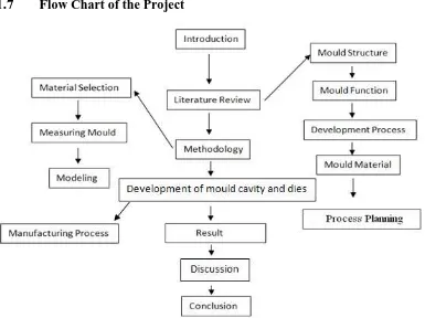
1.7 Flow Chart of the Project
Figure 1.1: Flow chart of the project
1.8 Schedule of the project
Figure 1.2 below show the plan of schedule for the first part of the project:
Task/Week 1 2 3 4 5 6 7 8 9 10 11 12
Literature Review Mould Study
Data Collection Refinement
Analysis
Verification
Drawing
Writing Up
7
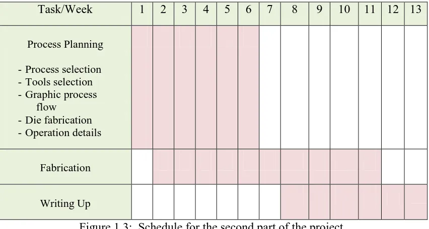
Figure 1.3 below show the plan of schedule for the second part of the project:
Figure 1.3: Schedule for the second part of the project
1.9 Summary
Overall in this project will more concentrate on the mould design, material selection for product and the mould base, analysis and modeling the cavity mould, measure the existing mould by using CMM, study the injection moulding machine function and selection development process for the mould fabrication.
Task/Week 1 2 3 4 5 6 7 8 9 10 11 12 13
Process Planning
- Process selection - Tools selection - Graphic process
flow
- Die fabrication - Operation details
Fabrication