UNIVERSITI TEKNIKAL MALAYSIA MELAKA
Design Validation And Development Of Hand Phone
Housing Plastic Injection
Mould (Cavity
)
Thesis submitted in accordance with the partial requirements of the Universiti
Teknikal Malaysia Melaka for the Bachelor of Manufacturing Engineering
(Manufacturing Process)
By
Mohd Zulhilmi Bin Nawang
(B050410326)
Faculty of Manufacturing Engineering
UTeM Library (Pind.1/2007)
UNIVERSITI TEKNIKAL MALAYSIA MELAKA
%& & ,
Design Validation And Development Of Hand Phone Housing
Plastic Injection Mould (Cavity)
' '-.*% *- , /001+/002
MOHD ZULHILMI BIN NAWANG
" !+ + #
& 3 ! ! "& !# 4 ,
5$ & 3 ! ! $
/$ & 3 ! !
$ 6$
$ 7$ " #
&
'()*
*8 '()* "!
! *8 * (*) * (* ! 591/#
"! '()*
+ #
" *- * *-.*- '-& #
* ,
- : 8 //0/0 %
, /0 !*; /002
,
" *- * *-.*- '-;' *#
< ( ,
DECLARATION
I hereby, declared this thesis entitled “Design validation and Development of Hand phone Housing Plastic Injection Mould (Cavity).” is the results of my own research
except as cited in the reference.
Signature : ………
Author’s Name : MOHD ZULHILMI BIN NAWANG
APPROVAL
This PSM submitted to the senate of UTeM and has been as partial fulfillment of the requirements for the degree of Bachelor of Manufacturing Engineering (Manufacturing Process). The members of the supervisory committee are as follow:
ABSTRACT
ABSTRAK
DEDICATION
For my beloved parents, my family and to those who always gives me courage and
ACKNOWLEDGEMENTS
Alhamdulillah and Thank to Allah S.W.T. with all His Gracious and His Merciful for giving me strength and ability to accomplish this project research successfully. I would like to take the utmost opportunity to express my sincere and gratitude to my supervisor, Mr. Hassan Bin Attan who is always giving me supports and guidance throughout the year in completing this Final Year Project 1 & 2 until up to this stage in victory.
Also with the greatest thanks to my beloved parents and family who always pray and give the encouragement while pursuing my research and project. Their sacrifices are never being forgotten.
Besides, thanks a lot to Prof. Dr. Mohd Razali Bin Muhamad, Dean of Manufacturing Engineering Faculty, Universiti Teknikal Malaysia Melaka, Dr. Thoguluva Raghavan Vijayaram, and also Mr. Mohd Amri bin Sulaiman as well as to all lecturers of Faculty of Manufacturing Engineering. I also would like to convey my biggest appreciation to all FKP technicians for supporting me in accomplishes my Final Year Project without hesitation. All knowledge and experience I gained would not be forgotten.
TABLE OF CONTENTS
Abstract………... i
Dedication………... iii
Acknowledgement……….. iv
Table of Contents……… v
List of Figures………... ix
List of Tables……….. xii
Sign and Symbols………... xiii
1. INTRODUCTION……… 1
1.1 Project Background ……….………... 1
1.2 Problem Statement……….………. 2
1.3 Objective………..………... 2
..1.4 Scope………... 3
2. LITERATURE REVIEW………... 4
2.1 Type of Mold ………. 4
2.1.1 Cold Runner Mold ………... 6
2.1.1.1 Two Plate Mold……….. 6
2.1.1.2 Three Plate Mold……… 7
2.1.2 Hot Runner Molds……… 9
2.2 Mold Design….………...………... 9
2.2.1 Runner Design
………
92.2.2 Gate Design……….. 10
2.2.3 Location of Gates………. 10
2.2.4 Types of Gates……….. 11
2.2.6 Mold Venting……….. 12
2.2.7 Mold Cooling……….. 12
2.2.8 Ejector System……… 13
2.2.9 Part Design Consideration……….. 14
2.2.10 Molding Parameters……… 14
2.2.11 Mold Design Flow……….. 15
2.2.12 Feeding System Design……….. 16
2.2.13 Parting Design Module………... 17
2.3 Material Selection………... 18
2.3.1 Material for Product………. 18
2.3.2 Material for Construction of Mold………... 21
2.4 Software for 3D Modeling………... 22
2.5 CNC Machining……….. 25
2.5.1 Type of Instruction……….... 27
2.5.2 Movements……….... 27
2.5.3 Tool Changes……… 28
2.6 Rapid-prototyping……….. 28
2.6.1 Stereo-lithography……… 28
2.6.2 Selective Laser Sintering……….. 29
2.6.3 Three Dimensional Printing……….. 29
2.6.4 Ballistic Particle Manufacturing………... 29
2.6.4 Photo Chemical Machining……….. 29
2.6.6 Solid Ground Curing……… 30
2.6.7 Laminated Object Manufacturing……… 30
2.6.8 Fused Deposition Modeling………. 30
3. METHODOLOGY………... 31
3.1 Process Flow Methodology……… 32
3.2 Validation for 3D Model
…….
………... 333.5 Design of Cavity………. 38
3.5.1 Determination of the Parting Direction……….... 38
3.5.2 Recognition and Patching the “through” Holes……… 38
3.5.3Determination of parting lines and the extruding directions…….... 38
3.5.4 Generation of the Parting Surfaces………... 39
3.5.5 Creation of containing box………... 39
3.5.6 Generation of Cores and Cavities………. 39
3.6 Conduct Rapid Prototyping Process………... 40
3.7 Conduct the Machining Process ……… 40
4.
RESULT AND ANALYSIS
... 414.1 Introduction………... 41
4.2 Validate 3D Model Hand phone using Parametric Software and Modified The Previous Drawing……….... 41
4.3 Design of Feeding System……….. 47
4.4 Conduct mold flow analysis part by par………. 51
4.5 Part Arrangement and Feeding System Design……….. 58
4.6 Design The Cavity Plate of The Mold……… 65
4.6.1 Create parting line……… 65
4.6.2 Shut off surface……… 66
4.6.3 Create parting surface………... 66
4.6.4 Insert a tooling split……….. 67
4.6.5 Core and cavity plate………... 68
4.6.6 Cavity plate………... 68
4.6.7 Result of separating a mold into core and cavity plate………. 69
4.7 Rapid Prototyping………... 72
4.8 Process Planning………. 74
6. CONCLUSION AND RECOMMENDATION... 81
REFERENCES………. 82
LIST OF FIGURES
2.1 Mold assembly 4
2.2: Two plate mold in closed position 6
2.3: Two Plate Mold in open positions 7
2.4: Two plate mold 7
2.5: Three Plate Mold in Closed position 8
2.6: Hot Runner Vertical Mold 9
2.7: Ejector Pin System 13
2.8: System infrastructure for the mold design application 15
2.9: Parting design module 17
3.1: The original part of hand phone housing 33 3.2: The 3D part model of hand phone housing using SolidWorks 34
3.3: Defect on previous drawing 34
3.4: Example of Runner, gate design and part arrangement 36
3.5:
Example of mold flow analysis. 373.6: Example of mold flow analysis for part arrangement 37 4.1:
Front cover and back cover are not matching.
42 4.2:Battery slider and back cover is not matching
434.3: Battery cover (after modified) 44
4.4: Slider (after modified) 44
4.5 Camera cover (after modified) 45
4.6 Front cover (after modified) 45
4.7 Part assembly (isometric view) 46
4.8 battery cover mass properties 47
4.9 Mass properties of slider 48
4.10 Mass properties of Camera cover. 49
4.11 Mass properties front cover 50
4.12 Unsuitable node location for battery cover 51 4.13 Suitable node location for battery cover. 52
4.15 Camera cover with not suitable injection node 54 4.16 Camera cover with suitable injection node 54 4.17 Camera cover with suitable injection node 55 4.18 Mold flow analysis result for front cover 56 4.19 Mold flow analysis result for front cover 57 4.20 Example part that use circular gate. 58
4.21 part arrangement 1 59
4.22 Mold flow analysis for part arrangement 1. 59 4.23 Part arrangement 1 other gate location 60
4.24 Part arrangement 2 61
4.25 Mold flow analysis Part arrangement 2 61 4.26 Mold flow analysis after increasing size of gate. 62
4.27 Part arrangement 3 63
4.28 Part arrangement 3 with 1st idea of feeding system 63 4.29 Complete fill for part arrangement 2nd idea of gating system 64
4.30 Example of parting line 65
4.31 Example of Shut of surface 66
4.32 Parting surface 66
4.33 Tooling split 67
4.34 Solid body of cavity and core plate 68
4.35 Cavity plate 68
4.36 Cavity and core plate for battery cover 69
4.37 Cavity and core plate for slider 69
4.38 Cavity and core plate for front cover 70 4.39 Cavity and core plate for camera cover 70
4.40 Cavity plate for hand phone housing 71
4.41 Simulation movement of core and cavity, 71 4.42 Cavity Plate produce by 3D printer 72
4.43 3D printer during operation. 73
4.44 3D printer Machine. 73
5.3 The critical features for mold design 78 5.4 The critical features for mold design 79
5.5
Lifter system
795.6 A lifter shown with the mold closed 80
LIST OF TABLES
2.1 Acrylonitrile Butadiene Styrene/Polycarbonate Alloy - ABS/PC properties
19
LIST OF ABBREVIATIONS, SYMBOLS, SPECIALIZED
NOMENCLATURE
ABS - Acrylonitrile Butadiene Styrene
ABS/PC - Acrylonitrile Butadiene Styrene/Polycarbonate Alloy CAD - Computer Aided Design
CAM - Computer Aided Manufacturing CNC - Computer Numerical Control EDM - Electrical Discharge Machining PVC - Polyvinyl Chloride
LIST OF APPENDICES
A
Project Planning for PSM 1 and PSM 2
84
CHAPTER 1
INTRODUCTION
1.1
Project Background
Plastic industry is one of the world’s fastest growing industries, ranked as one of the few billion-dollar industries. Almost every product that is used in daily life involves the usage of plastic and most of these products can be produced by plastic injection molding method.
Plastic injection molding process is well known as the manufacturing process to create products with various shapes and complex geometry at low cost. The plastic injection molding process is a cyclic process. There are four significant stages in the process. These stages are filling, packing, cooling and ejecting. The plastic injection molding process begins with feeding the resin and the appropriate additives from the hopper to the heating/injection system of the injection plastic injection molding machine. This is the “filling stage” in which the mould cavity is filled with hot polymer melt at injection temperature. After the cavity is filled, in the “packing stage”, additional polymer melt is packed into the cavity at a higher pressure to compensate the expected shrinkage as the polymer solidifies. This is followed by “cooling stage” where the mould is cooled until the part is sufficiently rigid to be ejected. The last step is the “ejection stage” in which the mould is opened and the part is ejected, after which the mould is closed again to begin the next cycle.
must have correlation and suitable with the process that use plastic injection molding. The application of the mold design is applied according to the first to the last process. First, the sample parts and 3D drawing must be providing. Then, the 3D drawing of the product and mold is analyzed using the 3D modeling software. And lastly, for this study the machining process using CNC machines or EDM machine will be conduct to produce the final product.
1.2
Problem statement
The mold and part design of plastic parts for injection molding is a complicated process, considerations for producing a part ranging from cost and speed of production to structural, ergonomics and aesthetic requirements. One of the routines faced by a designer when designing quality into a part is the process of cavity balancing. This entails controlling the plastic flow in the filling phase such that the melt front reaches the boundaries of the mold at the same time. So That the design of the mold must start from validate the part and mold design to increase the quality of product and reduce the cost and production time. This study is focus on building cavity plate and design of feeding system for Nokia hand phone housing model 6680 that continuity of previous student project that focuses on Reverse Engineering, 3D modeling and machining simulate. The previous drawing of hand phone housing Nokia 6680 must be validating first. This is because the dimension of part need to precise and tolerance before mold making.
1.3
Objectives
to analyze the important of each part in hand phone cover to improve its design and to analyze the injection molding process to produce the product. The main objectives of the research are:
To build of a cavity plate for Hand phone housing.
To generate 3D model of a hand phone housing cavity plate. To do analysis of part arrangement with feeding system
1.4
Scope of Study
The scopes of study for this project are follows:
Validate the design of the hand phone housing (Model Nokia 6680).
Development of mold plastic injection molding for hand phone housing (Model Nokia 6680).
CHAPTER 2
LITERATURE REVIEW
This chapter is shows all about the information that related to this study such as method that will use in complete this study. All of this information is important to guide this study on gaining the objective of the study. This research is including the mold core and cavity and 3D solid modeling tools. The most suit mold to produce a hand phone housing product is the Three Plate mould.
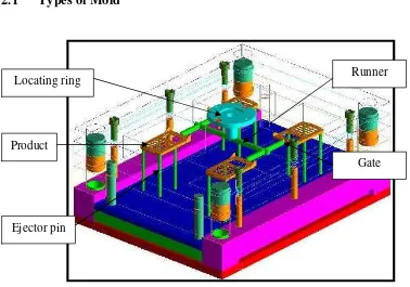
[image:22.612.118.496.390.655.2]2.1
Types of Mold
Figure 2.1: Mold assembly Locating ring
Product
Runner
Gate
A mould may have one cavity or several, even as many as 100, depending largely on part size. Multi-cavity moulds normally produce identical parts, though one type, known as a "Family" mould, is used to produce an assortment of parts later assembled as a single article. The main structural components of a mould are the mould plates, which, with the aid of pins and bushings, lock together to support and align the internal working parts of the mould. In operation, one mould half remains in a fixed position on the molding machine while the other is moved to and from the fixed half to accomplish mould closing and opening.
The fixed half of the mould contains a system of channels for delivery of melted resin to the mould cavity. This system consists of an entry port (sprue) which couples with 5 passages (runners) that convey resin from the sprue to the entrance way (gate) of the cavity. The part ejection mechanism is usually installed in the moving half of the mould. Moulds are equipped with a cooling system designed to withdraw heat from the melted resin in the cavity and thus cause the part or parts to solidify. Rapid cooling reduces machine cycle time and accelerates production, while uniformity in the rate of cooling throughout a part prevents warpage or undue shrinkage. Uniform part cooling requires that the most concentrated cooling take place in the vicinity of the hottest areas of the cavity (i.e. near the sprue and gates and, in parts of unequal thickness, in the areas of greatest thickness). Injection molding has two different types that were [2]:
1. Cold runner (two plate and three plate designs)
2. hot runner (the more common of the runner less molds)
2.1.1 Cold Runner
Molds Compared to the hot runner system, the cold runner mold type is very simple and cheaper. Due to its simplicity, that is why the mold requires less maintenance and less skill to set up and operate. Color changes easily since all the plastic in the mold is ejected with each cycle. So the product will be exchanged easily every time needed. The two plate and the three plate designs are the two major types of cold runner molds.
2.1.1.1
Two Plate mold
[image:24.612.144.482.428.672.2]The first type of cold runner molds is the two plates which is the simplest type of mold. Two plate molds has one parting line and two sections or halves. The runner system is be located on this parting line and the part must be gated on its perimeter as shown as Figure 2.2, Figure 2.3 and Figure 2.4. The runner is ejected together with the part for each time operates.
Figure 2.2: Two plate mold in closed position Stationary plate Water channels
Moveable plate
Ejector housing
Ejector plate
Ejector pin plate
Ejector pins Parting line
Cavity
Runner
Gate