UNIVERSITI TEKNIKAL MALAYSIA MELAKA
DESIGN FLEXIBILITY STUDY FOR PRODUCT
DEVELOPMENT USING DIRECT MODELING CAD SYSTEM
This report submitted in accordance with requirement of the Universiti Teknikal Malaysia Melaka (UTeM) for the Bachelor Degree of Manufacturing
Engineering Technology (Product Design) (Hons.)
by
TEE CHEE HONG B071210504 880114-43-5087
UNIVERSITI TEKNIKAL MALAYSIA MELAKA
BORANG PENGESAHAN STATUS LAPORAN PROJEK SARJANA MUDA
TAJUK: Design Flexibility Study for Product Development Using Direct Modeling CAD System
SESI PENGAJIAN: 2015/16 Semester 2
Saya TEE CHEE HONG
Mengaku membenarkan Laporan PSM ini disimpan di Perpustakaan Universiti Teknikal Malaysia Melaka (UTeM) dengan syarat-syarat kegunaan seperti berikut:
1. Laporan PSM adalah hak milik Universiti Teknikal Malaysia Melaka dan penulis. 2. Perpustakaan Universiti Teknikal Malaysia Melaka dibenarkan membuat salinan
untuk tujuan pengajian sahaja dengan izin penulis.
3. Perpustakaan dibenarkan membuat salinan laporan PSM ini sebagai bahan pertukaran antara institusi pengajian tinggi.
4. **Sila tandakan ( )
SULIT
TERHAD
TIDAK TERHAD
(Mengandungi maklumat yang berdarjah keselamatan atau kepentingan Malaysia sebagaimana yang termaktub dalam AKTA RAHSIA RASMI 1972)
(Mengandungi maklumat TERHAD yang telah ditentukan oleh organisasi/badan di mana penyelidikan dijalankan)
(TANDATANGAN PENULIS)
FAKULTI TEKNOLOGI KEJURUTERAAN
PENGKELASAN LAPORAN PSM SEBAGAI SULIT/TERHAD LAPORAN PROJEK SARJANA MUDA TEKNOLOGI KEJURUTERAAN PEMBUATAN (PRODUCT DESIGN): TEE CHEE HONG
Sukacita dimaklumkan bahawa Laporan PSM yang tersebut di atas bertajuk
“Design Flexibility Study for Product Development Using Direct Modeling
CAD System” mohon dikelaskan sebagai *SULIT / TERHAD untuk tempoh
LIMA(5) tahun dari tarikh surat ini.
2. Hal ini adalah kerana ianya merupakan projek yang ditaja oleh syarikat luar dan hasil kajiannya adalah sulit.
Sekian dimaklumkan. Terima kasih.
Yang benar,
________________
Tandatangan dan Cop Penyelia
v
DECLARATION
I hereby, declared this report entitled “PSM Title” is the results of my own research except as cited in references.
Signature : ………
Name : ………
vi
APPROVAL
This report is submitted to the Faculty of Engineering Technology of UTeM as a partial fulfillment of the requirements for the degree of Bachelor of Manufacturing Engineering Technology (Product Design) (Hons.). The member of the supervisory is as follow:
vii
ABSTRACT
viii
ABSTRAK
ix
DEDICATIONS
x
ACKNOWLEDGMENTS
xi
TABLE OF CONTENTS
DECLARATION ... v
APPROVAL ... vi
ABSTRACT ... vii
ABSTRAK ... viii
DEDICATIONS ... ix
ACKNOWLEDGMENTS ... x
TABLE OF CONTENTS ... xi
LIST OF FIGURES ... xv
LIST OF SYMBOLS AND ABBREVIATIONS ... xviii
CHAPTER 1 ... 1
1.0 Introduction ... 1
1.1 Background ... 1
1.2 Objective ... 2
1.3 Scope ... 2
1.4 Research Flow ... 2
CHAPTER 2 ... 4
2.0 Introduction ... 4
2.1 Multiple-CAD System ... 4
2.1.1 Ship Layout Design System ... 4
xii
2.1.4 Locomotive Design System ... 11
2.1.5 Overview for Design Systems ... 13
2.2 CAD Interoperability ... 14
2.2.1 Product Life Management (PLM) ... 14
2.3 Overview of CAD/CAM/CAE ... 16
2.3.1 Rapid Prototyping ... 16
2.3.2 Finite Element Modeling... 17
2.4 Data Translation Formats ... 18
2.4.1 Initial Graphic Exchange Specification ... 19
2.4.2 Standard for the Exchange of Product Model Data ... 20
2.4.3 Stereo Lithography ... 21
2.4.4 Drawing Exchange Specification ... 22
2.5 Overview Injection Molding ... 23
2.5.1 Two-Plate Molds ... 23
2.5.2 Three-Plate Molds ... 24
2.5.3 Side-Action Molds ... 25
2.6 Materials foe Injection Molding ... 26
2.6.1 Thermoplastics ... 27
2.6.2 Thermosets ... 28
CHAPTER 3 ... 29
3.0 Introduction ... 29
xiii
3.1.1 Traditional Modeling Concept ... 30
3.1.2 Direct Modeling Concept ... 31
3.2 Product Design ... 32
3.2.1 Design Brief and Project Constraint ... 33
3.2.2 Redesign & Free Sketches ... 33
3.3 Product Development ... 34
3.3.1 Upper Body Frame ... 35
3.3.2 Lower Body Frame ... 40
3.3.3 Base Part... 43
3.4 System Level Design ... 46
3.4.1 Configuration Design ... 46
3.4.2 Parametric Design of Multi-CAD System ... 47
3.5 Detail Design ... 49
3.6 Evaluation and Refinement ... 49
3.6.1 Ergonomics Study ... 50
3.6.2 Injection Mold Design Consideration ... 50
3.6.3 Final Design Product ... 51
CHAPTER 4 ... 53
4.0 Introduction ... 53
4.1 Technical Result ... 53
4.1.1 Ergonomic Factor ... 53
4.1.2 Manufacturing Process ... 57
xiv
5.0 Justification of Objective ... 65
5.1 Review of Method ... 65
5.2 Review of Findings ... 67
5.3 Design Tool Contribution ... 67
5.4 Design Tool Limitation ... 67
5.5 Implication ... 68
5.6 Recommendations ... 68
APPENDIX A ... 69
APPENDIX B ... 72
xv
LIST OF FIGURES
CHAPTER 2
Figure 2.1: A Data Structure for Solid Models ... 5
Figure 2.2: Siemens CAD/CAM/CAE Software for Automotive Industry ... 7
Figure 2.3: A High-Speed Civil Transport (HSCT) ... 9
Figure 2.4: An Aeroelastic iteration loop in the CAD system ... 10
Figure 2.5: The Engine Intake Port System ... 12
Figure 2.6: Concept of PLM ... 15
Figure 2.7: A Complex Aircraft Profile ... 17
Figure 2.8: Data Loss File IGES and STEP during Translating Data ... 19
Figure 2.9: The Components List of the STEP Standard ... 20
Figure 2.10: An Incorrect Solid Model with STL File ... 21
Figure 2.11: A PCB frame with DXF File ... 22
Figure 2.12: The Bill of Material for Two-Plate Mold ... 24
Figure 2.13: An Opening View of Three-plate Mold ... 25
Figure 2.14: An Exploded View of the Side-action Mold ... 26
Figure 2.15: Market Segments for Injection Molded Products in Europe ... 27
CHAPTER 3 Figure 3.1: A Sample of Prototype ... 29
Figure 3.2: Traditional Flow Process ... 31
Figure 3.3: Direct Modeling Flow Process ... 32
Figure 3.4: A Sheet Metal Model in SolidWorks ... 33
Figure 3.5: Housing of Hand Dryers’ Free Sketches ... 34
Figure 3.6: SolidWorkss’ CAD File ... 35
Figure 3.7: Imported File in Platform SpaceClaim ... 36
Figure 3.8: Separated Half Model ... 36
Figure 3.9: Rounded Model ... 37
xvi
Figure 3.12: The New Pattern of Curved Surface ... 39
Figure 3.13: A Redesign Model for Upper Body ... 40
Figure 3.14: A Separated Lower Body ... 41
Figure 3.15: Rounded Lower Body ... 42
Figure 3.16: A Preview of Model Combination ... 42
Figure 3.17: Viewports for Upper and Lower Body Frame ... 43
Figure 3.18: A Direct Model for Sheet Metal ... 44
Figure 3.19: Viewports for Upper and Lower Body Frame ... 44
Figure 3.20: Single Viewport and Wireframe View for Product Assembly ... 45
Figure 3.21: Adjustment and Modification for Assemble Parts ... 48
Figure 3.22: Detail Drawing Features ... 49
Figure 3.23: Delmia Virtual Ergonomics Study for Hand-dryer Users ... 50
Figure 3.24: Draft Analyses of Parts ... 51
Figure 3.25: Samples of Rendering Product Model for Hand-dryer ... 52
CHAPTER 4 Figure 4.1:Translation from SpaceClaim to CATIA... 54
Figure 4.2: Simulation for Vision Assessment and Hands Movement ... 54
Figure 4.3: Recommended Height Installation of Hand-dryer... 56
Figure 4.4: Degree of Rising Hands Versus Wall-Height Installation Chart ... 56
Figure 4.5: A Translation from SpaceClaim to SolidWorks ... 58
Figure 4.6: A Run of Draft Analysis in the SolidWorkss ... 58
Figure 4.7: A Run of Undercut Analysis in SolidWorks ... 59
Figure 4.8: A Failure of DraftXpret Feature in SolidWorks ... 60
Figure 4.9: A Data Translation from SpaceClaim to KeyShot ... 61
Figure 4.10: Final Product Image after KeyShot Rendering... 62
Figure 4.11: The KeyShots’ Design Features & Platform ... 63
Figure 4.12: Washroom Background for Product Application ... 64
xvii
LIST OF TABLE
CHAPTER 3
Table 3.1: List of Standard Parts and Components ... 46
CHAPTER 4
xviii
CAD = Computer Aided Design
CAM = Computer Aided Manufacturing
CAE = Computer Aided Engineering
CFD = Computational Fluid Dynamics
2D = Two-Dimensional
3D = Three-Dimensional
STEP = Standard for the Exchange of Product
Model Data
STL = Stereo Lithography
IGES = Initial Graphic Exchange Specification
DXF = Drawing Exchange Format
SCDOC = SpaceClaim Document
NURBS = Non-Uniform Rational B-Spine
1
CHAPTER 1
INTRODUCTION
1.0 Introduction
Computer Aided Design (CAD) system is started around the mid-1970s to provide more efficiency than manual drafting with electronic drafting. Now, CAD systems are used to develop a geometric model of the product from the conceptual ideas. Especially for manufacturers, design product can be developed to include material and manufacturing information with a geometric model of a design. In CAD design system, an integral part that can be considered is the geometric modeling that can be built with a wire-frame model, surface model or solid model. But, most of the industries are related to the multi-disciplinary projects that involving a large of sharing data information among vendors for designing various parts of their end product.
1.1 Background
2
to study the CAD interoperability issues for handling CAD conversion, geometric translation and its feature-based design in a CAD system.
1.2 Objective
The need for sharing information which involving in a multi-disciplinary project has been requested by manufacturers or suppliers, to choose a flexibility CAD system that can be developing a CAD model with quickly and efficiently. This concept is chosen as the CAD system developer because it represents an average CAD system which to access manufacturers and suppliers acceptance if such a CAD system. The purpose of this report is to identify the result of a state-of-the-art investigation of a 3D modeling CAD system product development. This report is including a demonstration of the practical side of its process.
.
1.3 Scope
The main consideration in proposing a flexibility CAD system provided a CAD data transfer that fulfils the need to satisfy each of these functions even in a different uses of CAD data formats. The CAD system must have giving benefits such as quick action, easy to use, and acceptance by each of users. Other aspects like the function of CAD models and the CAD simulation analysis will not be covered in this project. The CAD system should be focus mainly by CAD to CAD users in developing and presenting their product development models.
1.4 Research Flow
3
4
CHAPTER 2
LITERATURE REVIEW
2.0 Introduction
This chapter will discuss mainly on the various knowledge of theoretical and experiences of experimental in Multiple-CAD System, CAD Interoperability, Overview of CAD/CAM/CAE, Data Translation Formats, Overview Injection Moulding, and Material for Injection Moulding.
2.1 Multiple-CAD System
This section describes the current situation how manufacturers to develop a model of product with existing various parts of different CAD data file. In a multi-CAD system, it holds a lot of multi-CAD data file. The purpose of using multiple types of file is given a heavy data load can be distributed as many different files instead of having all information in one file. Because of many heavy industries like the automotive, aerospace, shipbuilding, heavy equipment manufacturer and their supplier are using multi-file types to handle the separate tasks required for modeling versus detailing simplifies the interaction between both tasks.
2.1.1 Ship Layout Design System
5
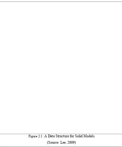
used to develop a ship’s infrastructure; Not only architectural analysis software can make it, even the general-purpose computer aided design system such as AutoCAD, Eagle, or Inventor also can be considered to build it. In fact, a large of components that creates part by part for the internal geometry of the ship including its representation and utilization. In the design stage, designers are not necessarily required to their design and functionality of a tool into a most suitable model. Because of the designers were thought about the design reconsideration and subsequently redesign for improvement purpose (Koningh, 2011).
Figure 2.1: A Data Structure for Solid Models
6
non-manifold solid model as Figure 2.1 given above. Each of the solid models, manifold and non-manifold, has their pros and cons. But, the multiple representation methods are used to apply on the ship layout design and its software system. The important thing is, designers should focus on the representation of the internal geometry of the ship. It likely rooms, spaces, holds or compartments are either modeled as volumetric entities or with the aid of bulkheads and decks or the mixed use of volumes and planes. There are various ship hull representations even different file types solid models (volume), surface models (plane), or wireframe model (plane). They need convert all different format files into a neutral file such as Standard for the Exchange of Product Model Data (STEP), Initial Graphic Exchange Specification (IGES), Stereo Lithography (STL) and other CAD data that can readable and can be applied in parts combination of a product model. Even having a neutral file as their standard rule for saving files, they offer higher chance given the greater possibility of interoperability issues to their CAD system.
2.1.2 Automotive Design System
7
team instead of purchasing extra CAD software or third-party data converter which is expensive (General Motors Co., n.d.).
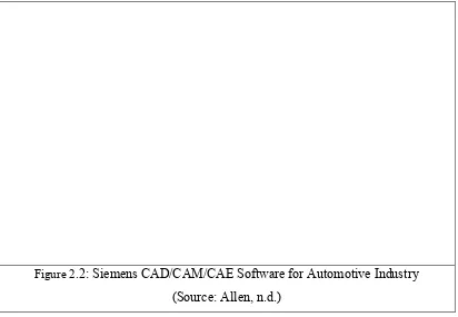
Figure 2.2: Siemens CAD/CAM/CAE Software for Automotive Industry
(Source: Allen, n.d.)
An example of the literature review from Siemens CAD/CAM/CAE software shown that the automotive manufacturers are used their software technology apparatus. To develop the important parts of car or components likely car body, chassis, engine, architectural structure, styling frame, and wiring planning in the CAD system. The following Figure 2.2 shown as above, a general process flow of making a car started from the product development stage to the manufacturing planning and fulfilment stage. A way that designers that can predict and minimize the errors or problems of making a car; to ensure the final products can be exposure and good performance in the competitive markets. Unlike the customers, which focus mostly on the car performance and market price. The automotive manufacturers often have an intrinsic interest in the detailed specification for fulfilling customer demands and have been professionally successful in the field of automotive industry compared to the competitors.