UNIVERSITI TEKNIKAL MALAYSIA MELAKA
DESIGN AND ANALYSIS OF SHAFT AND HOUSING
FOR FLYWHEEL HYBRID MODULE
This report submitted in accordance with requirement of the Universiti Teknikal Malaysia Melaka (UTeM) for the Bachelor's Degree in Mechanical Engineering
Technology (Automotive Technology) (Hons).
by
MUHAMMAD AIMAN BIN ABD NASIR
B071110395
910730-146507
DECLARATION
I hereby, declared this report entitled “Design and Analysis of Shaft and Housing
for Flywheel Hybrid Module”
is the results of my own research except as cited in references.
Signature : ……….
Author’s Name : ………
APPROVAL
This report is submitted to the Faculty of Engineering Technology of UTeM as a partial fulfillment of the requirements for the Bachelor's Degree in Mechanical Engineering Technology (Automotive Technology) (Hons). The member of the supervisory is as follow:
i
ABSTRAK
ii
ABSTRACT
The development of hybrid technology in vehicle nowadays are growing fast due to the hike of petrol price and increasing in environmental cautiousness among people in the world. Hybrid vehicles come with alternative power sources instead of only depending to the power produced by internal combustion engine to move a vehicle. Mechanical hybrid technology is a type hybrid technology that undergoes progressive development these days. This hybrid technology is used in Formula One Racing as the concern of Federation Internationale de l'Automobile (FIA) to the environmental cautiousness. This project aims to design and analyse the shafts and housing of Flywheel Hybrid module that will be integrated into front wheel of conventional motorcycles. The design stages of all the components follows the flow of mechanical engineering design process. The method used for concept selection is the scoring matrix or usually called as the Pugh Method. During benchmarking process, the specifications of shafts is studied. Then, the product development specification is determined to set the limit of dimensions for the whole Flywheel Hybrid module. Morphological chart consisting of ideas is prepared so that the ideas for every function in the module can be generated to form sets of components from different ideas to form a complete module in concept generation stage. Several concepts are selected based on the scores accumulated by the concept. Finally the sketching of conceptual design for the selected ideas combination is made to get the overview system of the Flywheel Hybrid module.
iii
DEDICATION
iv
ACKNOWLEDGEMENT
v
2.4 Bearing as the Friction-Reduction Component 8
2.5 Computer-Aided Design(CAD) and Finite Element Analysis(FEA) as the
Tool of the Study 10
CHAPTER 3: RESEARCH METHODOLOGY 11
3.1 Flowchart of the Bachelor's Degree Project 11
3.2 Benchmarking Process 13
3.3 Product Development Specifications 14
3.4 Conceptual Design 15
3.4.1 Morphological Chart 15
vi
3.7.1 Modelling of Shaft-Housing Unit 23
3.8 General Idea of FEA 24
3.9 Modelling of Shaft and Housing 25
3.10 Analysis of Shaft and Housing Using FEA 26
3.11 Material Properties 26
3.12 Finite Element Modelling 27
3.13 Setting the Boundary Conditions(Constraints) and Loads 29
3.13.1 Constraints 29
3.13.2 Loads 30
3.14 Computational Setup 31
CHAPTER 4: RESULT AND DISCUSSION OF FEA 33
4.1 Relationship between Angular Velocity and Displacement of Elements 33 4.2 Relationship between Angular Velocity and Von Mises Stress, and Von
Mises Strain of Elements 37
CHAPTER 5: CONCLUSION AND FUTURE WORK 46
REFERENCES 47
vii
LIST OF TABLES
3.1 Benchmark of three shafts manufacturers 13
3.2 Morphological Chart with scores given to each idea 16
3.3 Concept Generation Chart 18
3.4 Concept selection chart 19
3.5 Concept designs and their sketching 20
3.6 Mechanical properties of AISI 1018 Mild/Low Carbon Steel
21
3.7 Parameters and dimensions for the shaft and housing 22 3.8 Material properties of AISI 1018 Mild/Low Carbon Steel 27
3.9 Conversion of velocity 32
4.1 Contour of displacement of elements 33
4.2 Graph of magnitude of displacement at each element plot points
35
4.3 Element's von mises stress according to the pattern of contour
37
4.4 Element's von mises strain according to the pattern of contour
38
4.5 Graph of magnitude of von mises stress at each element plot points
41
4.6 Graph of magnitude of von mises strain at each element plot points
viii
LIST OF FIGURES
1.1(a) Yamaha LC135 V1 2
1.1(b) Yamaha LC135 V2 2
2.1 Shaft configuration to support and locate the two gears and two bearings
7
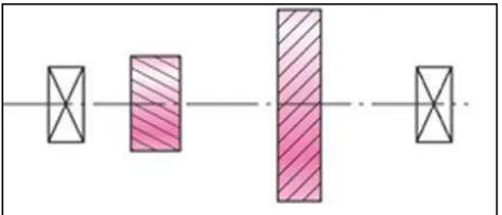
2.2 Example of stepped shaft 7
2.3 Example of ball bearings 9
2.4 Exploded view of a ball bearing and bearing outline in cross-sectional side view
9
3.1 Flowchart of the Bachelor's Degree Project 12
3.2 Flywheel hybrid module assembly 23
3.3 Multi view of the Shaft-Housing unit 24
3.4 Model of shafts and housing in CATIA V5R19 25
3.5 View of shaft and housing from the other angle shows that both part as a one piece component
25
3.6 Meshed Body of Shaft and Housing 28
3.7 Close-up view of the meshed body 28
3.8 Constraints and load 29
3.9 Position of rotation center 30
4.1 Plot points where the displacement value is picked up 34 4.2 Magnitude of element's displacement according to the plot points 36 4.3 Contour pattern seen from the other side of the body 39 4.4 Plot points where the value of element's von mises stess is
picked up
40
4.5 Plot points where the value of element's von mises strain is picked up
40
ix
4.7 Bar chart of maximum Von Mises Strain induced 43
4.8 Stress over strain for A = 41.0 rad/s 44
4.9 Stress over strain for A = 68.4 rad/s 45
1
CHAPTER 1
1. INTRODUCTION
1.1 Background of Study
The automotive industry nowadays has evolved basically from resources and human transportation to a whole new level such as racing events and researches. This trend of development is important to fulfill the demands of human needs. We cannot argue that the automotive industry plays a big role to move the world to current state of technology and economic structure. However, the current state of the environment, gas prices, and dependence on foreign oil leads the automotive industry to counter the drawbacks of its own development. The oil price worldwide is impossibly maintained nor reduced and the same goes to the current environment condition. These situations lead the people to greatly reduce the usage of fuel as well as reducing the emission level. By considering those factors, a hybrid vehicle is invented and widely used around the world. A hybrid vehicle is any vehicle that uses more than one fuel source. As such, an electric hybrid vehicle use two motors to make the vehicle run, an internal combustion engine that uses gasoline, and an electric motor. The electric motor is recharged during driving, both from the fuel burning in the engine and through the kinetic energy that is recaptured during braking. As a result, most current hybrid vehicles do not need to be plugged in to an electrical outlet to recharge the batteries.
2 battery to accumulate energy. The energy is absorbed during braking process using the regenerative braking system which is then released back when needed for acceleration As a result, most of the energy that is usually wasted during braking is used as a power to move the vehicle for a certain period of time. This somehow helps to reduce the fuel consumption and also the release of emission gas significantly. This technology also can be used in conventional motorcycles because currently in Malaysia, the percentage of motorcyclist is greater than that of the car users. All in all, the real advantage of flywheel energy is the high rate of energy input and release possible. This is particularly advantageous on regenerative braking system. This mechanical hybrid system also eliminates the use of wiring electronic control system that can make the system become more complex.
1.2 Problem Statement
The Flywheel Hybrid System will be installed into the front wheel of the system so that it will not interrupt the power transmission from the engine. The motorcycles model that is to be implemented with this system must be specific because each motorcycle has different size of front fork. Also, only motorcycle with front wheel brake disc system is chosen so that the whole part of the Flywheel Hybrid System can be placed in between the fork of the front wheel. The model of the motorcycle must also widely used nowadays to secure market place for this system. For this case, the most suitable motorcycle model is the Yamaha LC 135 which meet all the requirement above.
3 Both Yamaha LC135 V1 and Yamaha LC135 V2 have similar front wheel dimension. The flywheel hybrid system that will be produced should fit into both motorcycle models as they have the same wheel dimensions and configurations.
When designing the shaft and the housing of the Flywheel Hybrid module, lots of factors must be taking into account optimize the efficiency of the Flywheel Hybrid System. Those factors are:
Shafts are subjected to torque due to power transmission and bending
moment due to reactions on members that supported by them. The design and material selection of the shafts should be optimized so that they will not undergo stress deformation because of these factors.
Factor such as friction induced in rotating shaft may cause wear and generate excessive heat and loss to the surroundings. So, the shaft that is to be
designed must be able to transmit power as efficient as possible.
The flywheel hybrid module must be kept in a durable container such as housing to give protection from any external unwanted moving objects from the surrounding to keep it in optimal condition.
1.3 Objectives
There project consists of two objectives
1. To design the shaft and housing for flywheel hybrid module.
This will cover the design stages of all the components follows the flow of mechanical engineering design process.
2. To analyze the shaft and housing for flywheel hybrid module.
4
1.4 Project Scope
The Flywheel hybrid module will be used on the front wheel of conventional motorcycles. This project consists of designing and analysing the Flywheel Hybrid Module by following the engineering design process:
i. Conduct series of benchmarking for flywheel shafts and housing available in market and study the type, design and material of each shaft and housing product.
ii. Determine the customer requirements for flywheel shafts and housing and design several set of shafts and housing that meet the characteristics.
iii. Produce several conceptual designs of shafts and housing based on multiple parameters and types.
iv. List out several selected configuration design by referring to parameters such as orientation and dimension, solid or hollow circular cross-section etc. v. Generate an observable three dimensional design for each variable
characteristics and configurations using 3D CATIA software.
5
CHAPTER 2
2. LITERATURE REVIEW
2.1 Flywheel Hybrid System
Flywheel hybrid system is a hybrid system that uses a mechanical flywheel storage device instead of an electric battery. Both mechanical and conventional hybrid system applies the same concept of regenerative braking system. During braking process, the brake energy would normally be dissipated and wasted as heat during braking in a conventional vehicle. In contrast, vehicle with hybrid system would take benefit of that energy to aid it during acceleration (Lee, 2005).
6
2.2 Shaft as the Mechanism to Transfer Power
A shaft is a rotating member, usually in cylindrical shape, used to transmit power or motion. It provides the axis of rotation, or oscillation, of elements such as gears, pulley, flywheel, sprockets and many more. Ideally, shaft would be required to possess these criteria:
i. High strength
ii. Low notch sensitivity
iii. The ability to heat treated and case hardened to increase wear resistance of journals
In determining on an approach to shaft sizing, it is necessary to realize that a stress analysis at a specific point on a shaft can be made using only the shaft geometry in the vicinity of that point. So, the geometry of the entire shaft is not required. In design it is usually possible to locate the critical areas. Then, size these to meet the strength requirements. Finally, size the rest of the shaft to meet the requirements of the shaft-supported elements.
This project is focusing on designing a hollow shaft. This is because the (shaft) weight decreases more rapidly than the strength because the material near the center is not highly stressed and carries only a relatively small part of the total bending and torque loads. The reliability of the material is increased by using hollow shafts.
7 shoulder provides a solid support a solid support to minimize deflection and vibration of the components.
Figure 2.1: Shaft configuration to support and locate the two gears and two bearings
Shaft is usually made to have circular cross-section and could be either solid or hollow. Straight shaft is the most commonly used for power transmission. It is usually designed as stepped cylindrical bars with various diameters along its length. The stepped shaft corresponds to the magnitude of stress which varies along the length. Furthermore, the various diameters of a stepped shaft are designed to be compatible with assembly, disassembly and maintenance process. The design of stepped shaft would ease the fastening of the parts fitted to them, particularly the bearings. This is because bearings cannot be restricted against sliding in axial direction. The cross-section for each step in a stepped shaft must be that each part fitted onto the shaft has convenient access to its seat.
Figure 2.2 Example of stepped shaft
8
2.3 Housing as the Front Motorcycle Rim
A wheel or specifically a motorcycle rim is a circular device that is capable of rotating on its axis, facilitating movement while supporting a load or performing labor in machines. A wheel works together with an axle overcomes friction by facilitating motion by rolling motion. In order to make the wheels rotate, a moment needs to be applied to the wheel about its axis, either by means of gravity, or by applying another external force. Commonly the term is used for other circular objects that turn or rotate, such as steering wheel, fan blades, bicycle's wheel and flywheel. Steel disc wheel is a rim which possesses the steel-made rim and the wheel into by welding. It is mainly used for mopeds vehicle especially equipment tires (Saurabh & Sameer, 2013).
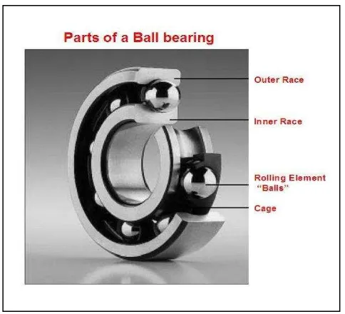
2.4 Bearing as the Friction-Reduction Component
Bearing used to hold shafts that rotate relative to fixed supports such as a housing. It is divided into two broad groups: journal and rolling contact. Journal bearings have no rolling elements. Instead, the shaft basically rotates within a polished sleeve that is lubricated by oil or another fluid. On the other hand, Rolling contact bearing comprises the following components:
An inner race
An outer race
Rolling elements in the form of balls, cylinders or cones.
9 Figure 2.3: Example of ball bearings
To illustrate how is the components of a rolling contact bearing function, the shaft and the bearing's inner race rotates together, while the outer race and the case are fixed (Lewis & Wickert, 2013).
10
2.5 Computer-Aided Design(CAD) and Finite Element Analysis(FEA)
as the Tool of the Study
11
CHAPTER 3
3. RESEARCH METHODOLOGY
3.1 Flowchart of the Bachelor's Degree Project
12
Start
Benchmarking Process
Product Development Specification
Morphological chart
Concept generation
Concept selection (concept scoring)
BDP 1
BDP 2 Conceptual sketching
conceptual design
Detailed Design
Analysis(CAD & FEA)
End
Parametric Design Configuration Design