UNIVERSITI TEKNIKAL MALAYSIA MELAKA
AUTOMATED STREETLIGHT MALFUNCTION ALERT
SYSTEM (ASMAS) BY USING GSM
This report is submitted in accordance with the requirement of the Universiti Teknikal Malaysia Melaka (UTeM) for the Bachelor Degree in Engineering
Technology (Electronic Industrial) with Honours
By
MOHAMAD HAFIZ BIN MAT B071210173
900913-03-5077
UNIVERSITI TEKNIKAL MALAYSIA MELAKA
BORANG PENGESAHAN STATUS LAPORAN PROJEK SARJANA MUDA
TAJUK: AUTOMATED STREETLIGHT MALFUNCTION ALERT SYSTEM (ASMAS) BY USING GSM
SESI PENGAJIAN: 2015/16 Semester 1
Saya MOHAMAD HAFIZ BIN MAT
mengaku membenarkan Laporan PSM ini disimpan di Perpustakaan Universiti Teknikal Malaysia Melaka (UTeM) dengan syarat-syarat kegunaan seperti berikut:
1. Laporan PSM adalah hak milik Universiti Teknikal Malaysia Melaka dan penulis. 2. Perpustakaan Universiti Teknikal Malaysia Melaka dibenarkan membuat salinan
untuk tujuan pengajian sahaja dengan izin penulis.
3. Perpustakaan dibenarkan membuat salinan laporan PSM ini sebagai bahan pertukaran antara institusi pengajian tinggi.
4. **Sila tandakan ( )
SULIT
TERHAD
TIDAK TERHAD
(Mengandungi maklumat yang berdarjah keselamatan atau kepentingan Malaysia sebagaimana yang termaktub dalam AKTA RAHSIA RASMI 1972)
(Mengandungi maklumat TERHAD yang telah ditentukan oleh organisasi/badan di mana penyelidikan dijalankan)
(TANDATANGAN PENULIS)
iv
DECLARATION
I hereby, declared this report entitled “Automated Streetlights Malfunction Alert
System (ASMAS) by using GSM Modem” is the results of my own research except
as cited in the references.
Signature :………...
Name : MOHAMAD HAFIZ BIN MAT
v
APPROVAL
This report is submitted to the Faculty of Engineering Technology of UTeM as a partial fulfillment of the requirements for the degree of Bachelor of Engineering Technology (Industrial Electronics) (Hons.). The member of the supervisory is as follows:
vi
ABSTRACT
vii
ABSTRAK
viii
DEDICATIONS
In the name of ALLAH the Most Gracious the Merciful Thousands of appreciation to ALLAH for giving me strength, strong, ideas and knowledge that helps me to finish this project.
ix
ACKNOWLEDGMENTS
x
xi
2.1.3 Relays ... 7
2.1.4 PIC16F877A Microcontroller ... 8
2.1.5 Global System for Mobile (GSM) ... 9
2.1.5.1 How to connect GSM Module with USB converter ... 10
2.1.5.2 How to testing GSM Modules ... 12
2.2 Short Message Services (SMS) ... 15
2.3 C Language ... 16
2.4 Hardware & Software for this system ... 16
2.5 How to construct interface for GSM by software ... 17
2.6 Related project research ... 19
2.6.1 Automatic Street Light Control System Using Microcontroller ... 19
2.6.2 Development Vehicle Tracking System using GSM/GPS Modem ... 19
2.6.3 Vehicle Location Finder using GSM and GPS ... 19
CHAPTER 3 ... 20
3.0 Flow Chart ... 20
3.1 Hardware Development ... 22
3.1.1 Light Sensor ... 22
3.1.2 Relay Interface ... 23
3.1.3 The Switching Malfunction System ... 24
3.1.4 PIC16F877A Microcontroller ... 25
3.1.5 SIM900A GSM/GPRS ... 26
xii
3.2 Block Diagram ... 28
3.3 Software Development ... 29
3.4 System flow for this project ... 30
CHAPTER 4 ... 31
4.0 Introduction ... 31
4.1 The Street Light Testing ... 31
4.2 The Malfunction Alert System Testing ... 32
4.3 Sending SMS Testing ... 33
4.4 Analysis ... 34
CHAPTER 5 ... 36
5.0 Introduction ... 36
5.1 Discussion ... 36
5.2 Conclusion ... 37
5.3 Recommendation ... 38
APPENDIX A ... 40
APPENDIX B1 ... 41
APPENDIX C1 ... 42
APPENDIX C2 ... 43
xiii
Figure Title Pages
2.0: Block Diagram………... 5
2.1: Light-dependent resistor (LDR)……… 5
2.2: Schematic Diagram LDR……….. 6
2.3: Regulated Power Supply……….. 6
2.4: Relay component………... 7
2.5: Schematic Diagram for relay………. 7
2.6: PIC 18F4550 Microcontroller……… 8
2.7: SIM900A GSM/GPRS………. 9
2.9: Connection GSM Module with Serial to USB converter……….. 11
2.10: Connection Single Berg Wires to CP2102 module‟s………... 11
2.11: Window icon Realterm………. 12
2.12: Window Realterm serial……….... 12
2.13: Window selects Baud Rate………... 13
2.14: Window for COM port………. 13
2.15 Window for port start communication………. 14
2.16: Window for GSM module type AT command……… 14
2.17: Window for GSM module receive SMS………. 15
2.18: Flow chart of the module system………. 17
2.19: COMPIM serial port model to the serial interface of GSM module……… 18
3.0: Flow chart of the project………... 22
3.1: Schematic LDR sensor………. 23
3.2: Interface relay diagram………. 24
3.3: Switching malfunction alert system……….. 25
3.4: PIC16F877A Microcontroller……… 26
3.6: GSM modem installed in the system……… 27
3.7: Adapter………. 28
3.9: Block diagram of the system………. 28
3.10: Development C- Language……….. 29
3.11: System flow of the project……… 30
4.1: System street light, functional………32
4.2: Malfunction alert system………... 33
4.3: System sending SMS to the user……… 33
xiv
LIST OF TABLE
Table Title Pages
2.8: Pin description……….. 10
3.5: Port connection of the PIC microcontroller………. 26
3.8: Device voltage usage………. 28
1
CHAPTER 1
INTRODUCTION
1.0 Background
Capacity to detect the malfunction of the system and street lights automatically and the location where the malfunction occurred. Meanwhile, the number of street lighting systems around the world is too much. Thus, the development of street lighting malfunction alert system using Global System for Mobile Communications (GSM) modem implemented in order to enable authorities or maintenance to alert malfunction to the system automatically. The GSM specifications define the functions and interface requirements in detail but do not address the hardware. Where, the reason for this is to limit the designers as little as possible but still make it possible for the operators to buy equipment from different suppliers. For this network is divided into three major systems: the switching system (SS), the base station system (BSS), and the operation and support system (OSS).
1.1 Problem Statements
Too many demands on the use of street lighting led to oversee the work becomes more difficult and complex. During the surveillance camera system for street lighting is higher in cost (installation and maintenance).
2
1.2 Objectives
The objectives of this project are to:
a) To implement the interface PIC microcontroller with a GSM communication modem using the software.
b) To identify how GSM communication modem function for this system.
c) To analyze the system to be implemented using a wireless communications system its existing operation.
1.3 Scope
For this project, the model of street light made of simple timber and PIC microcontroller. This model uses instead of bulb 12V DC as a signaling device. This project also consists of a system that can detect alert bulb malfunction.
The bulb malfunction may happen because of the run in a long time. This system analyzes the output current of bulb and send to a PIC microcontroller.
3
This project can handle any weaknesses in the current street lighting system for wireless communications systems to track any damage or warnings automatically. Whereas, the system will automatically alert and this system will continue to send SMS to the authorities, including the location of the malfunction has been detected. Accordingly, with the wireless communication system, the malfunction can be repaired streetlights immediately upon notification.
1.5 Thesis Layout
This thesis was organized in six chapters. For detail explanation about the content of each chapter is as follows:
Chapter 1 to explain about the overview of the project about the alert malfunction of street lighting methods. This chapter contains the problem statement, objective, scope of project, project significant and thesis layout.
Chapters 2 focus on literature review on many previous projects related to this project. This literature review helps in giving the brief many ideas of this project.
Chapter 3 covers the methodology of this project, including the hardware development and software development.
Chapter 4 shows the result of this system. It consists the result of the hardware and software. Then, the discussion about the result was done.
Chapter 5 discusses about the management of the project. These chapters consist of the project Gantt chart for semester one and two.
4
CHAPTER 2
LITERATURE REVIEW
2.0 Introduction
Basically, street lighting is one of the important parts of a city‟s infrastructure where the main function is to illuminate the city‟s streets during the dark hours of the day. There are several factors need to be considered in order to design a good street lighting system such as night-time safety for community members and road users, provide public lighting at cost effective and the reduction of crime.
Furthermore, manual control is prone to errors and leads to energy wastages and manual dimming during midnight is impracticable. The current trend is the introduction of automation and remote management solutions to control street lighting.
This system consists of a central control system installed in command center; GSM mobile terminal networks. Information about the malfunction can be received from PIC microcontroller and send messages with the GSM network platform.
In this type sensor will be used as a light sensor. The light sensor detects darkness to turn ON / OFF switch, so the street lights would be willing to switch. LDR, which vary according to the amount of light falling on the surface, this is an inducement to whether it is a day-night time is controlled by PIC16F877A microcontroller and connected to a GSM modem.
5 authorities.
The block diagram as shown in Figure 2.0 on the street light system as shown consists of microcontroller, LDR sensor and GSM modem.
Figure 2.0: Block Diagram
2.1 Theoretical Background
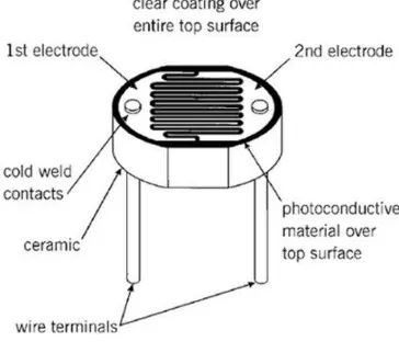
2.1.1 Light – Dependent Resistor (LDR)
The theoretical concept of the light sensor lies behind, which is used in this circuit as a darkness detector. The LDR is a resistor as shown Figure 2.1 and its resistance varies according to the amount of light falling on its surface. When the LDR detect light its resistance will get decreased, thus if it detects darkness its resistance will increase. (Ahmad Zaki bin Hj Shukor, October 2009)
6
Figure 2.1: Light – Dependent Resistor (LDR)
Figure 2.2: Schematic Diagram LDR
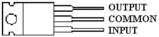
2.1.2 Regulated Power Supply
We start with an unregulated power supply ranging from a 9volt to 12volt DC. To make a 5volt power supply, KA8705 voltage regulator IC as shown Figure 2.3 has been used.
Figure 2.3: Regulated Power Supply
7
Relays are remote control electrical switches that are controlled by another switch, such as a horn switch or a computer as in a power train control module. Relays allow a small current flow circuit to control a higher current circuit. Relays, which come in various sizes, ratings, and applications, are used as remote control switches. This Figure 2.4 shows different types of relays. (Ahmad Zaki bin Hj Shukor, October 2009)
Figure 2.4: Relay Component
8
2.1.4 PIC16F877A Microcontroller
A microcontroller is a computer control system on a single chip. It has many electronic circuits built into it, which can decode written instruction and convert them to electrical signals. So, the microcontroller will then step through these instructions and execute them one by one. As an example of this a microcontroller we can use it to control the lighting of the street by using the exact procedures.
The microcontroller is now changing electronic design. Instead of hard wiring a number of logic gates together to perform some function we now use instructions to wire the gates electronically. The list of these instructions given to the microcontroller is called a program. These are different types of microcontroller, this project focus only on the PIC16F877A microcontroller where its pins as shown Figure 2.6.
9
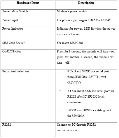
Global System for Mobile communications was a standard used in long distance data transfer with the use of cell network. (Firdaus bin Haji Sidek, 2010) Each network uses elevated tower that consists of transceivers which relays the data from one tower to another tower until it reaches the network provider. It is chosen as the medium for the transfer of location information. The simple and inexpensive Short Message Service (SMS) allows users to send up to 160 characters. It can be linked to a computer using DB9 header and simple RS232 board with the Hyper Terminal software. It uses AT command for SIM900A GSM/GPRS to configure the module as shown Figure 2.7 and as shown Table 2.8 is pin description.
10
Table 2.8: Pin description
Hardware Items Description
Power Main Switch Module‟s power switch
Power Input For power input, support DC5V – DC24V
Power Indicator Indicator for power. LED lit when the power
main switch is on.
SIM Card Socket For insert SIM Card
On/Off Switch Press for 1 second, the module will turn – on;
press for another 1 second, the module will turn – off.
Serial Port Selection i. STXD and SRXD are serial port
from SIM900A. LVTTL level (3.3V/5V)
ii. RTXD and RRXD are serial port for RS232 after IC SP3232 level conversion.
iii. DTXD and DRXD are debug port
for SIM900A.
RS232 Connect to PC through RS232
communication.
2.1.5.1 How to connect GSM Module with USB converter
11
other end of USB to CP2102 module‟s USB connector.
Figure 2.9: Connection GSM Module with USB converter
Therefore, the connect three Single Berg Wires to CP2102 module‟s RXD, TXD and GND pin as shown Figure 2.10. Then connect RXD wire to TXD of GSM module and TXD wire to RXD of GSM module. Make GND common by connecting the GND wire to GND pin of GSM module.