UNIVERSITY TEKNIKAL MALAYSIA MELAKA
MODELING OF HYDRO WIND TURBINE
This report submitted in accordance with requirement of the Universiti Teknikal Malaysia Melaka (UTeM) for the Bachelor Degree of Manufacturing Engineering
(Manufacturing Process)
by
NG KEN HOU B050710031
UNIVERSITI TEKNIKAL MALAYSIA MELAKA
BORANG PENGESAHAN STATUS LAPORAN PROJEK SARJANA MUDA
TAJUK: Modeling of Hydro Wind Turbine
SESI PENGAJIAN: 2010/11 Semester 2
Saya NG KEN HOU
mengaku membenarkan Laporan PSM ini disimpan di Perpustakaan Universiti Teknikal Malaysia Melaka (UTeM) dengan syarat-syarat kegunaan seperti berikut:
1. Laporan PSM adalah hak milik Universiti Teknikal Malaysia Melaka dan penulis. 2. Perpustakaan Universiti Teknikal Malaysia Melaka dibenarkan membuat salinan
untuk tujuan pengajian sahaja dengan izin penulis.
3. Perpustakaan dibenarkan membuat salinan laporan PSM ini sebagai bahan pertukaran antara institusi pengajian tinggi. atau kepentingan Malaysia yang termaktub di dalam AKTA RAHSIA RASMI 1972)
(Mengandungi maklumat TERHAD yang telah ditentukan oleh organisasi/badan di mana penyelidikan dijalankan)
Alamat Tetap:
DECLARATION
I hereby, declared this report entitled “Modeling of Hydro Wind Turbine” is the results of my own research except as cited in references
Signature :
Author’s Name : NG KEN HOU
APPROVAL
This report is submitted to the Faculty of Manufacturing Engineering of UTeM as a partial fulfillment of the requirements for the Degree in Bachelor of Manufacturing Engineering (Manufacturing Process). The member of the supervisory committee is as follow:
i
ABSTRAK
ii
ABSTRACT
iii
ACKNOWLEDGEMENT
First and foremost, I would like to express my deepest sense of gratitude and appreciation to my respected project supervisor, Associate Professor Ir. Sivarao A/L Subramonian, for his support, useful guidance, encouragement, valuable advice and constructive comments during the time this final year project was being developed. And not forget to my examiner and panel, Mr Mohd Fairuz Bin Dimin@Mohd Amin and Mr. Ammar Bin Abd Rahman respectively. Thank you for the guidance.
Next, I would like to thank all my course mates and friends, for their moral support and valuable help that they had offered to me throughout my course of studies.
Last but not the least, a special note of thanks is also dedicated to my classmate, Ow Yong Chia Hau in helping me to fabricate the hydro wind turbine model. Without his helping, the model will not fabricate successfully.
iv
DEDICATION
vi
3.2 Study of Existing Turbine 29 3.3 Conceptual Design 29
3.3.1 Concept One 29
3.3.2 Concept Two 30
vii
3.6.4.5 Wind Turbine Assembly 53
3.6.5 Water Turbine Fabrication 54
3.6.5.1 Turbine Blade 54
3.6.5.2 Frame 55
3.6.5.3 Water Turbine Assembly 55
3.6.6 Base Forming 56
3.6.7 Generator Fabrication 58
3.6.8 Hydro Wind Turbine Assembly 59
3.7 Test and Analysis 61
4.2.1 Assembly of CAD Components 68
4.2.2 Failure of Designed Hydro Wind Turbine 69
4.2.2.1 Incline Revolved Water Hose Overly Large 69
4.2.2.2 Water Hose and PVC Tube Diameter Excessively Big 69
viii
5. CONCLUSION & RECOMMENDATION 71
5.1 Conclusion 71
5.2 Recommendation 72
5.2.1 Wind Blade Design 72
5.2.2 Hose Cylinder Size 72
5.2.3 Slope of Revolved Hose 73
REFERENCES 74
APPENDICES 77
A 77
B 78
C 79
D 80
ix
LIST OF TABLES
2.1 Description of Nacelle Components 11
2.2 Description of Rotor Components 12
2.3 Description of Tower Components 13
2.4 Description of Balance of System Components 14
3.1 Concept Scoring Matrix 33
3.2 Materials Used for Water Turbine Fabrication 36
3.3 Materials Used for Wind Turbine Fabrication 37
3.4 Materials Used for Base Forming 38
3.2 Materials Used for Generator Fabrication 38
x
LIST OF FIGURES
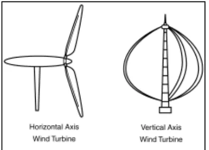
2.1 Two Basic Wind Turbines, Horizontal Axis and Vertical Axis 5
2.2 Components of a Wind Energy System 6
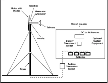
2.3 Wind Turbine Diagram 7
2.4 Schematic View of Wind Turbine 9
2.5 Schematic View of Wind Turbine Major components 9 2.6 Schematic View of Wind Turbine Major Subcomponents 10
2.7 Pelton Turbine with One Jet 16
2.8 Pelton Turbine with Four Jets 17
2.9 Francis Turbine 18
2.10 Kaplan Turbine 19
2.11 Working Mechanism of Hydro Plant 22
3.1 Flow Chart of Work 28
3.2 Schematic Diagram of Concept One 30
3.3 Schematic Diagram of Concept Two 31
3.4 Schematic Diagram of Concept Three 32
3.5 Main Parts of Hydro Wind Turbine 34
3.6a Third Angle Projection View of Hydro Wind Turbine 35
3.6b Detail Drawing of Hydro Wind Turbine 35
xi
3.24 Screwing of Lathed Shaft to the Frame 50
3.25 Complete Frame 50
3.26 Holes for Cable Tight 51
3.27 Tighten the Water Hose with Cable Tight 51
3.28 Complete Hose Cylinder 51
3.29 Riveting of Wind Blade 52
3.30 Completed Wind Blade 52
3.31a Wind Blade Screwing 53
3.31b Hose Cylinder Screwing 53
3.32 Assembled Wind Turbine 53
3.33 Sticking of Zinc Plate on Nut 54
3.34 Completed Turbine Blade 54
3.35 Water Turbine Frame 55
3.45 Position of Hydro Wind Turbine Components on the Fiber Base 59
3.46 Connection of Water Turbine and Generator 60
3.47 Assembled Hydro Wind Turbine Model 60
3.48 Head Specially Fabricated for Water Flow Testing 62
xii
3.50 Clamping Head Using Handrill 62
3.51 Water Flow Distance 63
4.1 Hydro Wind Turbine Model 65
A1 Gantt Chart for PSM I 77
A2 Gantt Chart for PSM II 77
B1 Detail Drawing for Wind Turbine 78
C1 Detail Drawing for Hydro Turbine 79
D1 Detail Drawing for Base 80
xiii
DG - Distributed Generators
HTGS - Hydro Turbine Generating Sets IG - Induction Generator
MHPP - Micro Hydro Power Plant
MIG - Metal Inert Gas
MPT - Maximum Power Tracking
MWPT - Micro Wind Power Turbine
NDE-HS - Nonlinear Differential Equations for Hydraulic System PMSG - Permanent Magnet Synchronous Generator
PVC - Polyvinyl Chloride RPM - Revolution Per Minute
SCIG - Squirrel Cage Induction Generator
SPS - Sim Power System
1
CHAPTER 1
INTRODUCTION
This chapter describes about the background of the project and briefly explains about the problem statement for this project. Then, the goals and scope of the project are identified. Finally, the proposed solution is briefly discussed.
1.1 Background
Renewable energy sources are the natural resources that are inexhaustible. Renewable energy sources have attracted attention world-wide due to soaring prices of fossil fuels. Renewable energy sources are considered to be important in improving the security of energy supplies by decreasing the dependency on fossil fuels and in reducing the emissions of greenhouse gases. Importantly, renewable energy produces virtually no greenhouse gas emissions. This can protect earth from pollution. Examples of renewable energy are wind, hydropower, solar, geothermal and biomass.
2
Hydropower is energy that comes from the force of moving water. The force of moving water can be extremely powerful. Hydropower is called a renewable energy source because the water on the earth is continuously replenished by precipitation. Hydro energy uses water to create power. Hydropower converts the energy in flowing water into electricity. Most hydroelectric power comes from the potential energy of dammed water driving a water turbine and generator. The quantity of electricity generated is determined by the volume of water flow and the amount of "head". “Head” is the height from turbines in the power plant to the water surface created by the dam. The greater the flow and head, the more electricity produced.
1.2 Problem Statement
The light of alert sign board that located at the dangerous and isolated area like sea is operated by using battery at night. But battery has the limitation of short usage lifetime and cannot provide a long term power generation. Furthermore, the replacement of new battery in this isolated place is trouble and inconvenience.
1.3 Objective
The objectives of this project are to: i. Design a hydro wind turbine.
ii. Develop a hydro wind turbine model. iii. Investigate the preliminary operation.
1.4 Scope
3
1.5 Proposed Solution
4
CHAPTER 2
LITERATURE REVIEW
This chapter contains of literature review on the types, development and application of wind turbine, hydro turbine and wind hydro turbine.
2.1 Wind Turbine
Wind turbines used to generate electricity come in a wide variety of sizes. Large wind turbines, which are usually installed in clusters called windfarms, can generate large amounts of electricity. Large wind turbines may even produce hundreds of megawatts of electricity, enough to power hundreds of homes. Small wind turbines which are generally defined as producing no more than 100 kW of electricity, are designed to be installed at homes, farms and small businesses either as a source of backup electricity, or to offset use of utility power and reduce electricity bills.
5
Patel, D. et al. (2010) have analyzed the impact of wind turbine generators on network resonance and harmonic distortion. First, a representative study system is devised where the impact of different elements of power system on system resonance frequencies is analyzed. Then the influence of system background harmonics on harmonic distortion is shown for the study system as well as for one of the actual Hydro One distribution feeder systems. It is shown that several scenarios are possible when these resonant frequencies align with harmonic frequencies that are likely to be injected by other power electronic based system equipment including distributed generators (DGs), thus causing unacceptable total harmonic distortion. Results for the study system further shows that the addition of a specific number of SCIG‟s may cause an unacceptable value of THD due to network resonance.
2.1.1 Types of Wind Turbine
There are two basic types of wind turbine which are horizontal axis wind turbines and vertical axis wind turbines. Figure 2.1 shows the two basic types of wind turbines. Horizontal axis turbines need to be aimed directly at the wind. Because of this, they come with a tailvane that will continuously point them in the direction of the wind. Vertical axis turbines work whatever direction the wind is blowing, but require a lot more ground space to support their guy wires than horizontal axis wind turbines. (Clarke, 2003).
6
2.1.2 Components of Wind Energy Systems
There are four basic components of typical wind energy system which are including rotor, gearbox, enclosure and tail vane. Figure 2.2 shows the basic components of a typical wind energy system. A rotor is consisted of blades with aerodynamic surfaces. When the wind blows over the blades, the rotor turns, causing the generator or alternator in the turbine to rotate and produce electricity. Gearbox is matched to the rotor speed to that of the generator or alternator. The smallest turbines which are under 10 kW usually do not require a gearbox. The function of enclosure or nacelle is to protect the gearbox, generator and other components of the turbine from the elements. A tailvane or yaw system is used to align the turbine with the wind. Horizontal axis wind turbine is mounted on a tower and vertical axis turbines are usually built on the ground. (Clarke, 2003).
7
2.1.3 Current Wind Turbines
Today‟s wind turbines use blades to capture the wind‟s kinetic energy. Wind turbines work because they slow down the speed of the wind. When the wind blows, it pushes against the blades of the wind turbine, making them spin. They power a generator to produce electricity. Most wind turbines have the same basic parts which are blades, shafts, gears, a generator, and a cable. Some turbines do not have gearboxes. These parts work together to convert the wind‟s energy into electricity. (National Energy Education Development Project, 2010).
Figure 2.3: Wind turbine diagram (National Energy Education Development Project, 2010).