“I have read this literary work and that in my opinion it is fully adequate, in scope and quality, as a masterpiece for the degree of
Bachelor of Mechanical Engineering (Structure & Material)”
MODELING AND SIMULATION OF HORIZONTAL WIND TURBINE BLADE
FAZLY BIN BUANG
This report submitted in partial
fulfillment of the conditions of the award of a Degree in Mechanical Engineering (Structure & Material)
Faculty of Mechanical Engineering Universiti Teknikal Malaysia Melaka
“I declared that this project report entitled “Modeling and Simulation of Horizontal Wind Turbine Blade” is written by me and is my own effort except the
idea and summaries which I have clarified their sources.”
v
ACKNOWLEDGEMENT
All praises to God for His blessings and guidance. Thanks for giving me strength to complete this project report. I am really grateful as I have completed this Projek Sarjana Muda with the help and support, encouragement and inspirations by various parties. All the knowledge and information that they give are really helpful.
Here I would like to express my gratitude to Mr. Nazri bin Md. Daud which is my supervisor for all his supports and advices during the completion of this project. All the helps, knowledge and advices through a few consultations increase my confident level in completing this project report.
vi
ABSTRACT
vii
ABSTRAK
viii
CONTENT
CHAPTER TOPIC PAGE
ACKNOWLEDGEMENT v
ABSTRACT vi
CONTENT viii
LIST OF FIGURES xi
LIST OF TABLES xiii
CHAPTER 1 INTRODUCTION 1
1.1 Background 1
1.2 Problem statement 2
1.3 Objectives 3
1.4 Scope 3
1.5 Project summary 3
CHAPTER 2 LITERATURE REVIEW 4
2.1 Introduction 4
2.2 Modeling of the wind turbine power
generating system 4
ix
CHAPTER TOPIC PAGE
2.5 Simulation of wind turbine blade 7
2.6 Two dimensional aerodynamics 8
CHAPTER 3 METHODOLOGY 9
3.1 Proposed project methodology 9
3.2 Design of horizontal wind turbine blade 11
3.3 Design specification 14
3.4 Blade analysis 15
3.5 Boundary condition 16
CHAPTER 4 RESULT AND DISCUSSION 19
4.1 Simulation result 20
4.1.1 Result for 0o angle of blade 21 4.1.2 Result for 30oangle of blade 23 4.1.3 Result for 45oangle of blade 25 4.1.4 Result for 60oangle of blade 27
4.2 Data analysis 29
4.3 Discussion 32
CHAPTER 5 CONCLUSION 35
REFERENCES 37
x
LIST OF FIGURE
NO. TITLE PAGE
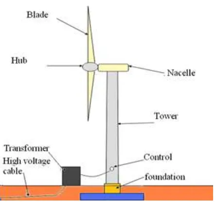
1 Major Turbine Components for a Wind Turbine 2
2 Performance Comparison between Twisted and
Non-Twisted Wind Turbine Blade 5
3 Blade 3-dimensional Shape 6
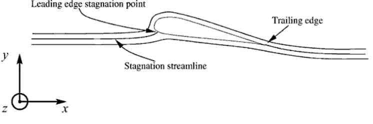
4 Schematic View of Streamline past an Aerofoil 8
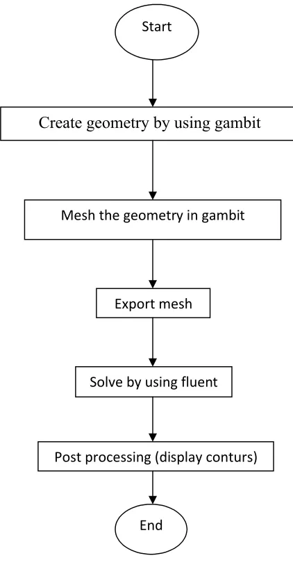
5 Flowchart of the Methodology 10
6 Isometric view of blade design 11
7 Blade with boundary 12
8 Meshed model 13
9 Dimension of wind turbine blade (top view) 14
10 Side view dimension 14
11 Step to set the unit 15
12 Definition of model properties 16
xi
NO. TITLE PAGE
14 Boundary condition setup 18
15 Pressure distribution for 6.5m/s wind speed 21
16 Pressure distribution for 7m/s wind speed 21
17 Pressure distribution for 7.5m/s wind speed 22
18 Pressure distribution for 6.5m/s wind speed at 30o angle 23 19 Pressure distribution for 7m/s wind speed at 30o angle 23 20 Pressure distribution for 7.5m/s wind speed at 30o angle 24 21 Pressure distribution for 6.5m/s wind speed at 45o angle 25 22 Pressure distribution for 7m/s wind speed at 45o angle 25 23 Pressure distribution for 7.5m/s wind speed at 45o angle 26 24 Pressure distribution for 6.5m/s wind speed at 60o angle 27 25 Pressure distribution for 7.0m/s wind speed at 60o angle 27 26 Pressure distribution for 7.5m/s wind speed at 60o angle 28
27 Maximum pressure (Pa) versus wind speed (m/s) 29
xii
LIST OF TABLES
NO. TITLE PAGE
1 Value of maximum and minimum pressure at the blade
for 0o angle 22
2 Value of maximum and minimum pressure at the blade
for 30o angle 24
3 Value of maximum and minimum pressure at the blade
for 45o angle 26
4 Value of maximum and minimum pressure at the blade
for 60o angle 28
5 Height of fluid difference of manometer 31
6 Maximum pressure (experimental) 32
7 Percentage error for 0o blade angle 33
8 Percentage error for 30o blade angle 34
9 Percentage error for 45o blade angle 34
1
CHAPTER 1
INTRODUCTION
1.1 Background
2
Figure 1:Major Turbine Components for a Wind Turbine
Many other countries such as America have used this kind of technology besides to have other choice of energy sources. Nowadays, all energy sources are reduced because of the age of the earth. Its need a new initiative to overcome this problem. Wind turbine is the one of the initiative that can replace the past energy source. The design of the drive train and the blade will affect the performance of the wind turbine.
1.2 Problem Statement
3
1.3 Objectives
The objective of this project involved is to determine the pressure distribution on the blade of small wind turbine with different angle.
1.4 Scopes
The scope that focus in this project are;
1. Determination the pressure distribution of horizontal wind turbine blade. 2. Comparison of pressure distribution for blade with different angle. 3. Simulation of horizontal wind turbine blade by using fluent software.
1.5 Project Summary
4
CHAPTER 2
LITERATURE REVIEW
2.1 Introduction
A literature review in this chapter will content with just a simple summary of the sources such as journal and papers related to the horizontal wind turbine. In this chapter, it will also include some of the details about horizontal wind turbine, the power generating system
2.2 Modeling of the Wind Turbine Power Generating System
5
2.3 Design of Non-Twisted Wind Turbine Blade
In this journal written by R. Lanzafame and M. Messina, ‘Design and Performance of a Double Pitch Wind Turbine with Non-Twisted Blades’, a new layout for small wind turbine blades has been presented. The new wind turbine blade is subdivided into two parts, each non-twisted, with a variable chord along the radius, a particular pitch angle, and a winglet to connect the two parts. The optimum choice of pitch angle provides the best blade aerodynamic condition and maximizes the power coefficient. To choose the correct pitch angles, a model-based design was needed. The code enabled the wind turbine power coefficient in the design wind speed to be maximized, and the wind turbine performances in all the off-design operating conditions to be evaluated. In the final stage, the performance of the new wind turbine was compared with those of standard non-twisted blades wind turbine which highlighted the advantages of the new design. It offers optimum aerodynamic flow and presents a power output gain in all the wind-speed ranges.
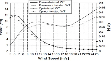
[image:17.612.214.449.493.622.2]Beside that, to create an inexpensive wind turbine, the blades can be non-twisted with a variable chord along the rotor radius. This type of wind turbine produces lower performances both in design and off-design operational conditions. There are some comparisons of the non-twisted and twisted wind turbine blade shown in Figure 2.
Figure 2: Performance Comparison between Twisted and Non-Twisted Wind Turbine Blade
6
2.4 Dual Rotor Wind Turbine Generator System
Reviewed from the J.H. Moon et.al (2009), “Modeling, Control, and Simulation of Dual Rotor Wind Turbine Generator System”, introduced a dual rotor wind turbine generator system which consists of two rotors. The one is small auxiliary rotor at the upwind location and the other relatively larger main rotor at the downwind location. The general equations of motion for the constrained multi-body system were used to obtain the dynamic model for this new wind turbine generator system, and a nonlinear simulation program was developed to predict its performance and test the pitch control algorithm. Blade element and momentum theory and a simple flow interaction model were used to calculate the aerodynamic forces and torques. The doubly fed induction generator was treated as a single rotating body requiring a torque for power production.
In this journal, it also explains about lift and drag forces created by the rotor blades that will eventually provide the thrust force and torque to the WTGS. As was mentioned, given the aerodynamic and geometrical characteristics of the rotor blades, the power and torque coefficients are calculated using the blade element and momentum theory. The properties of the blade will affect lift and drag forces and can make the performance higher. An example of the blade is shown in Figure 3.
7
2.5 Simulation of Wind Turbine Blade
According to Nilay Sezer-Uzol and Lyle N. Long (2006), “3D Time Accurate CFD Simulations of Wind Turbine Rotor Flow Fields”, Three-dimensional flow properties of rotating blades are an essential feature of any wind turbine aerodynamic simulation. While important information can be learned from two-dimensional and non-rotating simulations, some aspects of the physics of wind turbine aerodynamics and noise must be obtained from rotating blade simulations. Three dimensional flows over rotating blades can be significantly different than the flow over a wing, and there can also be dramatic differences between 2-D and 3-D simulations.
In addition, rotating blades can have significant radial flow and also the blade speed varies linearly from root to tip. The three-dimensional wake of a rotating blade can remain in close proximity to the blade for a long period of time compared to the wake of a wing. By incorporating time dependent boundary conditions, either a gust or turbulent incoming flow can be introduced. Chyczewski et.al have done this in the past with jet noise predictions, to simulate turbulence levels inside the nozzle and their effect on the jet shear layers and noise. For these reasons, time-accurate three-dimensional and compressible rotating blade simulations are essential. There have been several CFD studies of wind turbine flow fields using different approaches in the literature.
2.6 Two-Dimensional Aerodynamics
8
[image:20.612.145.518.254.378.2]In order to realize a 2-D flow it is necessary to extrude an aerofoil into a wing of infinite span. On a real wing the chord and twist changes along the span and the wing starts at a hub and ends in a tip, but long slender wings, like those modern gliders and wind turbine. Shown in Figure 4, the local 2-D data for the forces can be used if the angle of attack is corrected accordingly with the trailing vortices behind the wing. This effect will be dealt with later, but it is now clear that 2-D aerodynamics is of practical interest even though it is difficult to realize.
9
CHAPTER 3
METHODOLOGY
10
3.1 Proposed Project Methodology
[image:22.612.211.422.210.618.2]The project methodology of this project can be more easily described by producing a type of flowchart that consists of certain step involved to finish the project. This flowchart in Figure 5 will show the flow of the process of analyzing horizontal wind turbine blade with all method used in this project.
Figure 5 : Flowchart of the Methodology Create geometry by using gambit
Start
Mesh the geometry in gambit
Export mesh
Solve by using fluent
Post processing (display conturs)
11
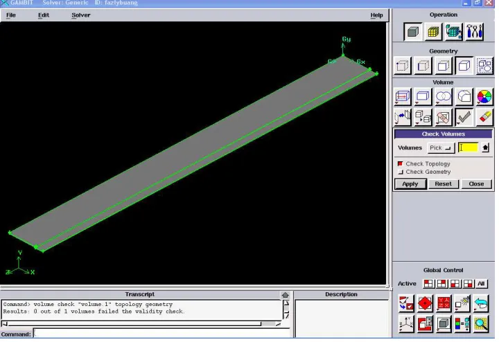
3.2 Design of Horizontal Wind Turbine Blade
The design of the blade will be created by using gambit in CFD software. From the gambit, the geometry created can be extruded by using sweep command. For the information, CFD is a part of Computer Aided Engineering (CAE) that have high demand in industry. This software included two dimensional and three dimensional cases. For this current project, it required to use three dimensional cases to valid the requirement of the title of project. There are some procedures or step that must be followed while create the blade geometry.
[image:23.612.149.509.440.687.2]Modeling is one of the critical stages due to the influence of the final results. Some action that might be important during the design process is creating the basic shape of the model. By using gambit, it must started by creating the vertex or coordinate for certain point. Then, it will be sweep to get a three dimensional model. This model will mesh with the same software.
12
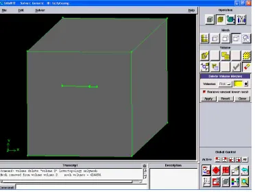
[image:24.612.145.517.282.562.2]For this kind of case, it is an external flow analysis. So, the geometry or model must have a boundary for the simulation to solve the case. In this project, the square boundary used to create the velocity inlet and outlet flow. Then, the geometry of the blade will be cut through to build a surface to be analyzed. This step will produce a hole with the shape of the blade. All the dimension of the model are followed based on the real dimension in milimeter.