A STUDY ON THE F AlLURE ANALYSIS OF THE TIG WELDING WITH DISSIMILAR JOINT
WAN AHMAD FITRI BIN JOHARI
This report submitted in partial
fulfilment of the requirements for the award of a Bachelor of Mechanical Engineering (Structures & Materials)
Faculty of Mechanical Engineering Universiti Teknikal Malaysia Melaka
I .a tt•.J•
... :
JUNE2012
SUPERVISORS DECLARATION
I hereby, declared that I have read this thesis and in our opinion this report is sufficient
in terms of scope and quality for the award of the degree ofBachelor of Mechanical
Engineering (Structure & Material)
Signature
Supervisor
Date
: Mr. NAZRI HUZAIMI BIN ZAKARIA
DECLARATION
I hereby, declared this report entitled "On The Failure Analysis Of The Tig Welding
With Dissimilar Joints, is the results of my own research as cited in references.
Signature
Author's Name
Date
WAN AHMAD FITRI BIN JOHARI
30TH
JUNE
2012©
UnlveriiU Teknlkal Malaysia Melalal111
To my lovely parents and friends.
ACKNOWLEDGEMENTS
In
the name of Allah, the most Gracious and most Merciful,I am really grateful as I have completed this Projek Smjana Muda I with the help
and support, encouragement and inspirations by various parties. All the knowledge and
information that they give are really helpful.
iv
Here I would like to express my gratitude to Mr. Nazri Huzaimi Bin Zakaria which is
my supervisor for all his supports and advices during completion of this project.
All the helps, knowledge and ad vices through a few consultations
especially in material field.
And lastly not forgotten my beloved family, person and all fellow friends, for all
their concern, contribution, encouragement and understanding.
v
ABSTRACT
This project focuses on dissimilar joints metal by using TIG welding between dual phase steel and low carbon steel where only involve one type of joint that is square butt joint. Dissimilar joints metal between low carbon steel and dual phase steel is a common material that use in many indust:Iy, because the combination of this metal offer a good mechanical properties. However, welding joint is the weakest point in a component because most of the component failures occur at welding joints, so the purpose ofthis research is to investigate the failure analysis at that joint. We are using three methods or test to understand the behaviour of the joining for dual phase steel and low carbon steel. The control parameter is very important to avoid porosity, minor crack, and inclusion during the welding and to overcome those problems a good understanding on the behaviour of the joining is required. This project flow must start from cutting sample at welding workshop, heat treatment to produce dual-phase steel sample, welding process, visual analysis, mechanical testing and the last is analyze the result from the test before conclusion.
vi
ABSTRAK
Projek ini memberi tumpuan pada sa.mbungan logam mengunakan kimpalan
TIG diantara dua fasa keluli dan keluli karbon rendah dan hanya melibatkan satu
jenis sambungan sahaja. Keluli karbon rendah dan keluli dua fasa adalah bahan
biasa yang digunakan dalam kebanyakan industri, kerana gabungan logam ini
menawarkan sifat mekanikal yang baik. Walau bagaimanapun, kimpalan adalah titik
yang paling lemah dalam sesuatu komponen kerana kebanyakan kegagalan dalam
satu komponen berlaku pada sambungan kimpalan, tujuan kajian ini adalah untuk
menyiasat analisis kegagalan penyambungan tersebut. Untuk mencapai objektif
projek ini, terdapat tiga kaedah atau ujian untuk menganalisis ciri-ciri sambungan
tersebut, iaitu ujian tanpa musnah,ujian kekuatan dan ujian tegangan. Parameter
kawalan bagi kimpalan TIG adalah sangat penting untuk mengelakkan kecacatan
seperti keliangan, retakan kecil, dan kemasukkan semasa proses kimpalan. Aliran
.<
projek perlu bermula dari memotong sampel di bengkel kimpalan, rawatan haba
untuk menghasilkan sampel keluli dua fasa, proses kimpalan, analisis visual, ujian
mekanikal dan terakhir menganalisis basil dari ujian sebelum kesimpulan.
Vll
CONTENT
CHAPTER TOPIC PAGE
TITLE PAGE
SUPERVISOR DECLARATION 11
DECLARATION iii
ACKNOWLEDGMENT IV
ABSTRACT v
ABSTRAK VI
CONTENT Vll
LIST OF TABLES X
LIST OF FIGURES XI
CHAPTER I INTRODUCTION 1
1.1 Background of study 1
1.2 Objective 2
1.3 Scope 3
1.4 Problem Statement 3
CHAPTER2 LITERATURE REVIEW 4
2.1 Introduction 4
2.2 Tungsten Inert Gas (TIG) Welding 5
2.2.1 Advantages 5
2.2.2 Disadvantages 5
2.2.3 Filler Rod 6
2.2.4 Equipment 7
2.3 Mechanical Test 10
2.3.1 Tensile Test 10
2.3.2 Hardness test 12
2.4 Heat Treatment 13
Vlll
2.4.1 Physical Processes
13
2.4.2 Techniques 15
CHAPTER3 METHODOLOGY 19
3.1 Introduction 19
3.2 Project Flow Chart 20
3.3 Material 21
3.3.1 Low Carbon Steel 21
3.3.2 Dual Phase Steel 22
3.4 Sample Preparation 23
3.5 Heat Treatment Process 25
3. 6 Welding Process 26
3.6.1 TIG Welding Parameter 26
3 .6.2 Type of Joint 27
3 .7 Non-Destructive Testing 28
3. 7.1 Penetrant Testing Procedure 28
3 .8 Tensile Test 30
3. 9 Hardness Test 31
3.9.1 Procedure 32
CHAPTER4 RESULT AND DISCUSION 33
4.1 Introduction 33
4.2 Visual Analysis (Penetrant Test) 33
4.2.1 Specimen A 34
4.2.2 Specinien B 25
4.2.3 Specinien C 26
4.2.4 Specinien D 37
4.3 Hardness Test 33
4.3 .I Result 40
4.3.2 Discussion 44
4.4 Tensile Test 46
4.4.1 Result 47
4.4.2 Discussion 51
CHAPTER 5 CONCLUSION AND RECOMMENDATION 53
5.1 Conclusion 5.2 Recommendation
REFERENCES
APPENDICES
©
UnlveriiU Teknlkal Malaysia Melalal53
54
55
X
LIST OF TABLES
NO. TITLE PAGE
3.1
The parameters ofTIG Welding
26
4.1
Causes of porosity at welding joints
38
4.2
Hardness test result for specimen A
40
4.3
Hardness test result for specimen B
41
4.4
Hardness test result for specimen C
42
4.5
Hardness test result for specimen D
43
4.6
Average hardness test result for all specimen
444.7
Tensile test result for specimen A
47
4.8
Tensile test result for specimen B
48
4.9
Tensile test result for specimen C
49
4.10
Tensile test result for specimen D
50
4.11
Tensile test result
51
XJ
LIST OF FIGURES
NO. TITLE PAGE
2.1 Schematic diagram of the TIG welding process 5
2.2 TIG welding equipment 10
2.3 Test specimen nomenclature 11
2.4 Universal testing machine
11
2.5 Time-temperature isothermal transformation diagram 14
3.1 Flow chart for methodology 20
3.2 Schematic microstructure ofDP steel 23
3.3 Plat size (150 m.m, 65 mm, 9 mm) 24
3.4 Band saw machine is use to cutting sample 24
3.5 Phase diagram of an iron-carbon alloying system 25
3.6 Square edge butt joint 27
3 .7 Rockwell hardness tester 32
4.1 Specimen A for penetrant test 34
4.2 Specimen B for penetrant test 35
4.3 Specimen C for penetrant test 36
4.4 Specimen D for penetrant test 37
4.5 Location of eleven points at the specimen 39
xu
4.6 Hardness test graph for specimen A 40
4.7 Hardness test graph for specimen B 41
4.8 Hardness test graph for specimen C 42
4.9 Hardness test graph for specimen D 43
4.10 Average hardness test graph for all specimen 44
4.11 INSTRON-Model 8802 46
4.12 Graph load vs. extension for specimen A 47
4.13 Graph load vs. extension for specimen B 48
4.14 Graph load vs. extension for specimen C 49
4.15 Graph load vs. extension for specimen D 50
4.16 Graph for the tensile test result 51
1
CHAPTER!
INTRODUCTION
1.0 BACKGROUND
Dissimilar metal joining offers the potential to utilize the advantages of
different materials often providing unique solutions to engineering requirements. The
main reasons for dissimilar joining are due to the combination of good mechanical
properties of one material. However, each joint or a combination of dissimilar
metal will reach a stage where it will be failure, so the purpose of this research is to
investigate the failure analysis of TIG welding between dual phase steel and low carbon steel. These researches only involve one type of joint that is only square edge
butt joint The square edge butt joint is the easiest to prepare and can be welded
without filler rod. It consists of "butting'' two pieces of metal up against one another
(no overlapping) and then welding along the seam between them. If the weld is to be
made without filler rod, extreme care must be taken to avoid burning through the
metal.
Low-carbon steels include those in the AISI series C-1 008 to C-1 025. Carbon
ranges from 0.10 to 0.25%, manganese ranges from 0.25 to 1.5%, phosphorous is 0.4% maximum, and sulfur is 0.5% maximum [1]. Steels in this range are most
widely used for industrial fabrication and construction. These steels can be easily
welded with any of the arc, gas, and resistance welding processes. The largest
category of this class of steel is flat-rolled products (sheet or strip), usually in the
cold-rolled and annealed condition
2
Dual phase steel is defined as high strength low alloy steel (HSLA). Microstructure of dual phase steel consists ferrite and martensite. These two phase combinations give higher strength and improved ductility of the material. Dual phase steel can be produced by intercritical annealing process and followed by rapid cooling. Dual phase steel is an alternative material to be used where it improves the mechanical properties of low carbon steel [ 4]. Other than that, it can overcome the problem of metal component failure due to fracture and dual phase steel also cheaper than other metal. Welding analysis of dual phase steel material will be carried out in order to obtain better results of the joints.
Tungsten inert gas (TIG) welding is the process of blending together reactive metals. TIG welding is commonly used for both high quality and manual welding. During the process ofTIG welding, an arc is formed between a pointed tungsten electrode and the area to be welded. As a result of the gas shield, a clean weld is formed. This prevents oxidization from occurring [11]. The type of gas shielding typically used for TIG welding is argon, helium, or a combination of both. When combined, these two gases can ensure a higher welding speed and welding penetration. Argon is the preference of most welders when it comes to TIG welding. It is often used simply because it is heavier than air and provides better coverage when welding.
1.2 OBJECTIVE
The objectives of this research are:
1. To investigate the behavior ofTIG welding joint of dissimilar metal joining. 2. To evaluate the strength and toughness of the welding joint.
3. To investigate the types of defect in a surface of joint after Tungsten Inert Gas (TIG) welding using Non Destructive Testing (NOT).
3
1.3 SCOPES
The scopes of this research are:
1. Literature review on related studies.
2. Intercritical annealing heat treatment to produce dual-phase steel sample. 3. Involve Tungsten Inert Gas (TIG) welding.
4. Testing of the mechanical properties (Tensile and Hardness Test).
5. Visual Analysis to investigate types of defect in a surface of joint (Non Destructive Testing (NDT).
1.4 PROBLEMSTATEMENT
Dual phase steel and low carbon steel is widely used in automotive and concrete structure industry. A lot of research have been done on dual phase steel and prove that dual phase steel have good mechanical properties. Similar with several methods of joining, like welding, have been broadly performed between these metals because of the low price and high quality of this process. However, welding joint is the weakest point in a component because most of the component failures occur at welding joints.
In this study, a failure analysis of TIG welding and Gas welding will be carried out in order to understand the behaviour of the joining for dual phase steel and low carbon steel. The control parameter is very important to avoid porosity, minor crack, and inclusion during welding and to overcome those problems a good understanding on the behaviour of the joining is required.
TIG welding is a traditional of welding for alloy steel. However, some problems would be formed, such as hot cracking in fusion zone due to segregation of alloying elements during solidification, as cast coarse microstructure, which result in the obvious decrease of mechanical properties of the joints. A critical study on the optimum parameter setting of TIG welding will be done to obtain a good quality of joining.
4
CHAPTER2
LIT.ERATURE REVIEW
2.1 INTRODUCTION
With a reference from various source such as books, journal, notes, thesis and internet literature review has been carry out to collect all information related to this project. This chapter discussed about Tungsten Inert Gas (TIG) welding, Heat Treatment, Mechanical testing, visual Inspection (Non Destructive Testing (NDT) and Material Properties.
2.2 TUNGSTEN INERT GAS (TIG) WELDING
Tungsten Inert Gas (TIG) welding has been used in modem indust:Iy, especially for welding hard to weld metals such as stainless steel, titanium alloys and other materials for high quality weld. TIG welding process has some advantages, including high quality, easy and precise control of welding parameters. As a result, TIG welding has mainly used for welding the workpiece with thickness less than 6
mm.
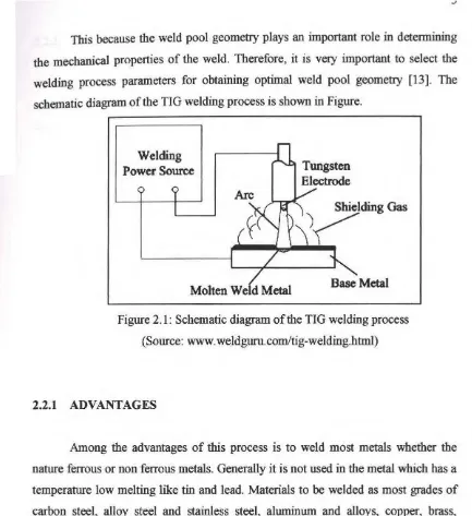
TIG welding which uses a nonconsumable tungsten electrode an inert gas for arc shielding is an extremely important arc welding process. Basically, TIG weld quality is strongly characterized by the weld pool geometry.
_,
This because the weld pool geomet:Iy plays an important role
in
determining the mechanical properties of the weld. Therefore, it is very important to select the welding process parameters for obtaining optimal weld pool geomet:Iy [13]. The schematic diagram of the TIG welding process is shown in Figure.Welding Power Source
[image:18.529.50.483.35.508.2]Molten
WeldMetal
Figure 2.1: Schematic diagram of the TIG welding process (Source:
www.
weldguru.com/tig-welding.html)2.2.1 ADVANTAGES
Among the advantages of this process is to weld most metals whether the nature ferrous or non ferrous metals. Generally it is not used in the metal which has a temperature low melting like tin and lead. Materials to be welded as most grades of carbon steel, alloy steel and stainless steel, aluminum and alloys, copper, brass, bronze, heat-resistant alloys, titanium, zikromium, gold and of silver [14].
Other advantage of this welding process is not occurring during the process of metal splashes the weld. This is because instead of the filler metal rod electrodes, so there is no metal across the arc as in the welding process, which using a consumable electrode. This process does not use the flux, so cleaning after welding is not normally required. Welding can be done at various positions [14].
6
2.2.2 DISADVANTAGES
The lack of this type of welding is slower than the process using a consumable electrode. Used in protective gas is supplied in separately. This increases the cost of welding, in addition to inert gas argon and helium used is expensive [14].
2.2.3 FILLER ROD
Filler metal is used to add metal to the weld zone during the the weld. It is found in the form of rods or wires. Filler metal may be coated with or without coating flux. The purpose of flux is used to delay oxidation on the surface of the welded components by gas protective zone around the weld. Flux also helps to dissolve and remove oxide and the workpiece, to produce a strong connection [15].
The resulting slag also protects the valley from the oxidation of the molten metal
as
it cools. In welding processes, filler metal consumption is important to help joint metal types, and vice versa. There are several types of metal common fillerssuch as:
1. Mixture of carbon steel with little or no mixture of carbon or no mixture of carbon (0.08 to 0.15% carbons)
2. Carbon steel
3. Low alloy steel Or high alloy stainless steel and manganese steel
4. Nickel and nickel-based alloys
5. Copper and copper-based alloy of cobalt-based alloy
6 . Aluminum 7. Magnesium 8. Titanium
7
In the selection of filler metal to help the merger of two iron type, there factors to consider:
• The importance of the nature of products.
• The features that should have a filler metal are selected.
• The extent to which the filler metal to assist in the welding process. • The effect of filler metal dilution on the quality of a connection. • Actual cost of the filler metal and the ability to be justified.
Selection of filler metals having compositions close to the metal Content the same is the best choice to influence the strength of a connection [ 15]. But the number of criteria must be followed in the selection:
• Filler metal during welding to maintain the structure and it will remain inert, insoluble, phase change and no catalytic activity.
• Filler metal has the same composition of the alloy content, or almost the same overall composition of the content of metal content to be welded. This is because the factors that determine a connection can connect to good or vice versa.
• Metal filler metal has helped to embed the same type or a differ in the automobile sector. Filler metal must be thermally stable and peruwapan no dilution process carried out.
• Filler metals in sufficient quantities at moderate prices uniform quality.
2.2.4 EQUIPMENT
The equipment required for the gas tungsten arc welding operation includes a welding torch utilizing a nonconsumable tungsten electrode, a constant-current welding power supply, and a shielding gas source.
8
2.2.4.1 Welding Torch
GT A W welding torches are designed for either automatic or manual
operation and are equipped with cooling systems using air or water. The automatic
and manual torches are similar in construction, but the manual torch has a handle
while the automatic torch normally comes with a mounting rack. Air cooling systems
are most often used for low-current operations (up to about 200 A), while water
cooling is required for high-current welding (up to about 600 A). The torches are
connected with cables to the power supply and with hoses to the shielding gas source
and where used, the water supply [20].
The internal metal parts of a torch are made of hard alloys of copper
or brass in order to transmit current and heat effectively. The size of the welding
torch nozzle depends on the amount of shielded area desired. The size of the
gas
nozzle will depend upon the diameter of the electrode, the joint configuration, and
the availability of access to the joint by the welder. The nozzle must be heat resistant
and thus is normally made of alumina or a ceramic material. Hand switches to
control welding current can be added to the manual GT A W torches [20].
2.2.4.2 Power Supply
Gas tungsten arc welding uses a constant current power source, meaning that
the current (and thus the heat) remains relatively constant, even if the arc distance
and voltage change. This is important because most applications of GT A W are
manual or semiautomatic, requiring that an operator hold the torch.
The preferred polarity of the GT A W system depends largely on the type of
metal being welded. Direct current with a negatively charged electrode (DCEN) is
often employed when welding steels, nickel, titanium, and other metals. It can also
be used in automatic GT A welding of aluminium or magnesium when helium is used
as a shielding gas.
9
The negatively charged electrode generates heat by emitting electrons which travel across the arc, causing thermal ionization of the shielding gas and increasing the temperature of the base material. The ionized shielding gas flows toward the electrode, not the base material, and this can allow oxides to build on the surface of the weld. Direct current with a positively charged electrode (DCEP) is less common, and is used primarily for shallow welds since less heat is generated in the base material [20].
2.2.4.3 Electrode
The electrode used in GT A W is made of tungsten or a tungsten alloy, because tungsten has the highest melting temperature among pure metals, at 3,422
oc
(6,192 °F). As a result, the electrode is not consumed during welding, though some erosion (called burn-oft) can occur. Electrodes can have either a clean finish or a ground finish-clean finish electrodes have been chemically cleaned, while ground finish electrodes have been ground to a uniform size and have a polished surface, making them optimal for heat conduction. The diameter of the electrode can vmy between 0.5 and 6.4 millimeters (0.02 and 0.25 in), and their length can range from 75 to 610 millimeters (3.0 to 24 in) [20].2.2.4.5 Shielding Gas
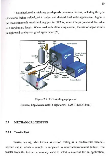
As with other welding processes such as gas metal arc welding, shielding gases are necessary in GT A W to protect the welding area from atmospheric gases such as nitrogen and oxygen, which can cause fusion defects, porosity, and weld metal embrittlement if they come in contact with the electrode, the arc, or the welding metal. The gas also transfers heat from the tungsten electrode to the metal, and it helps start and maintain a stable arc.
10
[image:23.529.57.481.22.635.2]The selection of a shielding gas depends on several factors, including the type of material being welded, joint design, and desired final weld appearance. Argon is the most commonly used shielding gas for GTAW, since it helps prevent defects due to a varying arc length. When used with alternating current, the use of argon results in high weld quality and good appearance [20].
Figure 2.2: TIG welding equipment
(Source: http://www.weld-it-rigbt.comffJGWELDING.html)
2.3 MECHANICAL TESTING
2.3.1 Tensile Test
Tensile testing, also known as tension testing, is a fundamental materials science test in which a sample is subjected to uniaxial tension until failure. The results from the test are commonly used to select a material for an application, for quality control, and to predict how a material will react under other types of forces. Properties that are directly measured via a tensile test are ultimate tensile strength, maximum elongation and reduction in area. From these measurements the following properties can also be determined: Young's modulus, Poisson's ratio, yield strength, and strain-hardening characteristics.
11
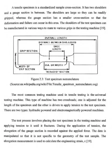
A tensile specimen is a standardized sample cross-section. It has two shoulders and a gauge section in between. The shoulders are large so they can be readily gripped, whereas the gauge section has a smaller cross-section so that the deformation and failure can occur in this area. The shoulders of the test specimen can be manufactured in various ways to mate to various grips in the testing machine [19].
GRIP SECTION
セwidtヲM
OF GRIP SECTIONOVERALL LENGTH
DISTANC :: BETWEEN SHOJLDERS
r
GAGEl
LENGTH
r
l ;--- ---;
セセセャa@ orwidhェ^セlNMMMセ@
.. REDUCED " SECTION
Figure 2.3 : Test specimen nomenclature
(Source:en.wikipedia.org/wiki/File:Tensile_specimen_nomenclature.svg)
The most common testing machine used in tensile testing is the universal testing machine. This type of machine has two 」イッウウィ・。、ウ セ@ one is adjusted for the length of the specimen and the other is driven to apply tension to the test specimen. There are two types: hydraulic powered and electromagnetically powered machines.
The test process involves placing the test specimen in the testing machine and applying tension to it until it fractures. During the application of tension, the elongation of the gauge section is recorded against the applied force. The data is manipulated so that it is not specific to the geometry of the test sample. The elongation measurement is used to calculate the engineering strain,
e
[19]. [image:24.529.62.489.42.611.2]