Dept. of Power Electronics and Drives, FKE, Universiti Teknikal Malaysia, Melaka, Skudai, Malaysia
∗∗
Dept. of Energy Conversion, FKE, Universiti Teknologi Malaysia, Johor, Skudai, Malaysia
∗∗∗
Dept. of Electrical Engineering, Universitas Ahmad Dahlan, Yogyakarta, Indonesia
†Dept. of Electrical Engineering, University of Akron, Akron, Ohio, USA
Abstract
This paper describes a hybrid induction motor drive system incorporating DTC-hysteresis and Direct Self Control (DSC) schemes to achieve excellent dynamic performance. The control scheme is switched from a circular to a hexagonal flux locus whenever a dynamic condition is encountered. On the other hand, when the motor operates under steady state conditions, a circular flux locus is used. Without major modifications to the simple structure of a basic DTC, hexagonal flux locus operation is established by modifying the flux error status, before it is fed to the look-up table. The feasibility of the proposed hybrid scheme to achieve excellent control performance is verified by experimental results.
Key Words: Direct Self Control, Direct Torque Control, Hexagonal flux locus, Induction Motor
I. INTRODUCTION
In recent years, the Direct Torque Control (DTC) scheme for induction motor drives has received an enormous amount of attention in industrial motor drive applications. The main reason for its popularity is due to its simple structure, espe-cially when compared with the field-oriented control (FOC) scheme, which was introduced a decade earlier. Since DTC was first introduced [1], several variations on its original structure have been proposed to overcome the inherent disad-vantages in any hysteresis-based controller such as, a variable switching frequency, a high sampling requirement for digital implementation and a high torque ripple [2]–[9].
The most popular variation on the DTC of induction motor drives is one that is based on space vector modulation (SVM), which is normally referred to as DTC-SVM [10]–[16]. Contin-uous improvements utilizing this technique have gained much momentum in order to facilitate DTC to operate in overmodu-lation mode to fully utilize the available DC voltage. In DTC-SVM it is possible to operate in overmodulation mode which is defined based on the reference voltage vectors generated
Manuscript received Oct. 20, 2010; revised May 20, 2011
Recommended for publication by Associate Editor Kyeong-Hwa Kim. † Corresponding Author: [email protected]
Tel: +330-972-6531, Fax: +330-972-6487, University of Akron
∗Dept. of Power Electronics and Drives, FKE, Universiti Teknikal Malaysia
Melaka, Malaysia
∗∗Dept. of Energy Conversion, FKE, Universiti Teknologi Malaysia, Skudai,
Malaysia
∗∗∗Dept. of Electrical Engineering, Universitas Ahmad Dahlan, Indonesia
by controller. However, in DTC-hysteresis based control, this is not possible simply because there is no reference voltage available.
In SVM, overmodulation mode starts whenever the refer-ence voltage vector goes beyond the hexagonal boundary of the voltage vector plane. It is well known that the operation of overmodulation is very important in many electric drive applications in order to improve the power output and dynamic performance. In fact, the fastest torque dynamic and the high capability of the torque in a flux weakening region can be achieved if the stator voltage is able to operate in six-step mode. For these reasons, many researchers had shown significant interest in developing methods for estimating the maximum possible reference voltage during torque dynamic [15]–[17]. For examples, [16] utilized predictive control of the stator flux error vector to estimate the reference voltage and [15] used dead-beat control with several complicated equations to generate the reference voltage in real-time. Among the various schemes proposed, only [16] and [18] can achieve fast torque dynamic control and maximum torque capability in the flux weakening region with six-step voltage operation. Unfortunately, all of the proposed methods [15]–[17] increases the complexity of the DTC control structure and deviates from the simple drive structure as originally proposed in [1].
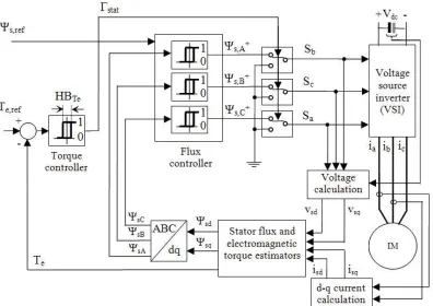
Fig. 1. Structure of Direct Self Control based induction machine.
Fig. 2. Typical waveforms in direct self control operation.
each scheme can be performed without the need for major modifications to the structure of basic DTC. In this paper, the principle of basic DTC will not be explained since this scheme is well-known and has been widely discussed in many technical papers. However, the principle of direct self control (DSC), which has similar operation to the hexagonal flux control in the hybrid scheme, will be briefly explained in Section II. In Section III of this paper, a detail explanation of the construction and operation of the proposed hybrid scheme will be presented. Section IV demonstrates the high performance of the hybrid scheme. Section V presents both its implementation and experimental results. Finally, a conclusion is given in Section VI.
(a) (b)
Fig. 3. Control of flux vector to a hexagonal shape with the appropriate voltage vectors. (a) Stator flux plane (b) Voltage vector plane.
Fig. 4. The structure of hybrid induction motor drive with the proposed block of ‘modification of flux error status’ (to perform DSC operation).
Fig. 5. The appropriate digital outputs in modified flux error status Ψs−
correspond to the optimized voltage vectors for every sub sector in each sector.
II. BASICPRINCIPLE OFDIRECTSELFCONTROL
The control structure of the direct self control (DSC) proposed by M. Depenbrock [18] is depicted in Fig. 1. Unlike DTC, DSC does not require sector identification and a lookup table for selecting the voltage vector. Moreover, it operates on the basis of hexagonal flux control where the active voltage vectors (v1, v2, v3,..,v6) used to form the hexagonal
shape are determined according to the appropriate digitized outputs (Ψs,A+, Ψs,B+ and Ψs,C+). The digitized outputs
generated from three units of hysteresis comparators are based on the command of the stator flux (Ψs,re f) and the phase
flux components (ΨsA,ΨsB andΨsC). Meanwhile, the torque
hysteresis comparator produces the signal that determines zero voltage vector (v0 or v7) when the output torque satisfies its
demand (Γstat=0). For a constant flux region, the generation
of the switching states (SaSbSc) which determine the voltage
vectors can be described by the following equations:
Sa=Ψ+s,A, Sb=Ψ+s,B, Sc=Ψ+s,C forΓstat=1 (1)
Sa=0, Sb=0, Sc=0 for Γstat=0. (2)
Fig. 7. Flux keeps the increase as it enters to sub sector 2 until it reaches to the pointc. (i.e. pathb-c) with theΨs,mod−=0.
which is useful for identifying the application of the voltage vector (by examining the switching pattern in Fig. 2). The use of the zero voltage vector, which represents the satisfaction of the torque demand, is ideally halting the flux vector, thus it will not affect the flux trajectory.
It is well known that DSC is suitable for high power applications since it offers a lower switching frequency (for high power efficiency) and is superior in torque dynamic response. The lower switching frequency corresponds to a lower numbers of commutation in the switching states (i.e. the switching state Sa only commutates for a half cycle of
the flux), which decreases as the hysteresis band of the torque increases. However, this scheme produces a high current total harmonic distortions (THD) even when operating in steady state conditions.
III. THEPROPOSEDHYBRIDSCHEME
The hybrid scheme is proposed to facilitate operation of the conventional DTC scheme in dual-mode flux control. This section will discuss how the hexagonal flux locus is obtained with minor modifications to the conventional DTC control structure. The mechanisms and conditions for the transitions between a circular and a hexagonal stator flux locus will also be presented.
A. Hexagonal Flux Control in the Proposed Hybrid Scheme
In general, it is possible to establish hexagonal stator flux locus control using the conventional DTC control structure. To accomplish this one has to modify the lookup table as well as redefine the stator flux sector. This means that it is possible to interchangeably operate between DTC and DSC using the same control hardware. However, this method is not suitable, especially when frequent switching and smooth transitions between the two schemes are required. To overcome this, the proposed hybrid scheme in this paper uses a simple
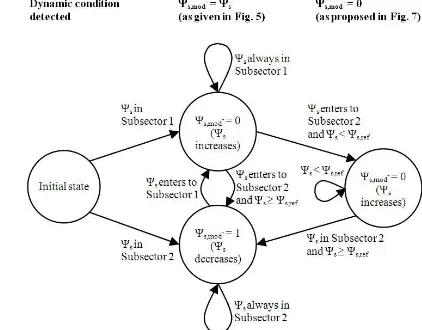
Fig. 8. State diagram of finite state machine that establishes the modified flux error status (Ψrms,mod−) to perform the proper hexagonal operation.
Fig. 9. Computation of references of torque and flux in the proposed hybrid scheme.
technique to establish a hexagonal flux locus without the need to modify the lookup table and redefine the stator flux sector. Fig. 4 shows the control structure of the hybrid DTC, which is similar to the conventional DTC control structure, but with an inclusion of the ‘modification of flux error status’ block. When the ‘modification of flux error status’ block is activated, the output of the hysteresis controller (i.e. the input to the block), Ψ+ is modified to Ψsnew and the stator flux locus
will be transformed to hexagonal. Otherwise, the block is not activated, Ψsnew = Ψ+ and the flux locus remains circular.
The activation of the block is performed whenever a dynamic condition is encountered and this is discussed further in part B of this section.
As can be seen in Fig. 5, each sector in the stator flux plane is divided into two sub sectors; subsector I (unshaded area) and subsector II (shaded area). The border of the sectors and the subsectors can be easily calculated using the threshold values of Ψs,qs, denoted asΨsq,1andΨsq,2, which are given as:
Ψsq,1=Ψss,d.tan(π/6) (3)
Ψsq,2=Ψss,d.tan(π/3). (4)
Fig. 10. The selection of flux error status in the block of modification of flux error status. (a) Original flux error statusΨ+s for circular locus. (b) Modified flux error statusΨs,mod− for hexagonal locus.
(a)
(b)
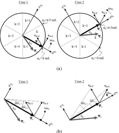
Fig. 11. Effects of selecting different switching under dynamic condition. (a) Stator voltage vector in stator flux. (b) Comparison of the load angle, δsr
generated by the same magnitude of appropriate voltage vectors.
Ideally, to produce a hexagonal flux locus, the stator flux error has to be set according toΨ−as illustrated in Fig. 5. For
example, the voltage vectorv4should be selected whenever the
flux is located between the middle of Sector II and the middle of Sector III. From the middle of Sector III to the middle of Sector IV, the voltage vector v5 should be chosen, and so forth. However, in practice the use ofΨs−to attain the desired
hexagonal flux locus as described above will not work. The locus of the flux may “shrink” as the speed increases although the motor should be operated in a constant flux region. This problem is illustrated by a simulation result as shown in the Fig. 6(a). In the simulation, the transition from a circular to a hexagonal locus starts at a (the middle of Sector II). At point b (the middle of Sector III), the flux fails to reach its reference. The reduction will continue as the flux moves from one vertex to another, and eventually, the size of the hexagonal is reduced. The shrinking of the hexagonal stator flux is due to the effect of the ohmic voltage drop that causes the trajectory of the flux motion to not align with the direction of the applied voltage vector. To explain this, consider the motion of the flux from point a (the middle of sector II) to point b (the middle
Fig. 12. More rapid motor acceleration achieved with the hybrid scheme when a step change of reference speed applied at time t1.
of sector III) as the vectorv4employed. A phasor diagram of
the related component vectors (i.e. change of the flux vector, applied voltage vector and ohmic voltage drop) is drawn based on the stator voltage equation, as depicted in Fig. 6(b). In this case the change of the flux vector fromatobcan be expressed as:
∆Ψa−b=vz.∆Tz+v4.∆T4−isrs.∆T (5)
wherevz is the zero voltage vector (this can be eitherv0 or
v7), and∆Tz and∆T4are the respective switching periods of
vz andv4. Hence, the time taken for the flux vector to travel
froma tobis given by:
∆T=∆Tz+∆T4. (6)
According to (5) and (6), the effect of the ohmic voltage drop (isrs), which causes the reduction of the flux, is affected
by ∆T, which is the summation of vz andv4. This indicates
that, the operation described above (the selection of Ψs− as
given in Fig. 5) can still become problematic even in the absence of the zero voltage vector. In fact, no matter how small the deviation angle between the vectors of the applied voltage and the flux change (φ), the locus of the hexagonal will still shrink (gradually) as the flux moves from one vertex to another.
It is desirable to keep the size of the hexagonal locus such that all six of the vertices are located on the circular reference in order to achieve proper torque control and hence maximum torque capability. The problem indicated in Fig. 6(a) can be solved if the applied active voltage for increasing the flux magnitude in subsector I is maintained until the flux reaches the circular reference, as illustrated in Fig. 7. In this case, the flux travels from point a to the point b by applying the flux error status as given in Fig. 5 (i.e. Ψs,mod−=Ψs−). However,
the flux error status, as given in Fig. 5, is modified to 0 (i.e. Ψs,mod−= 0) as the flux enters subsector II, until the flux
reaches point c. The generation of the modified flux error statusΨs,mod− to overcome the problem can be described by
a state diagram of a finite state machine as shown in Fig. 8.
B. Definitions of the dynamic conditions.
(a) (b)
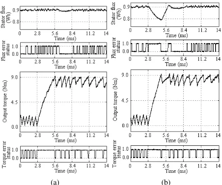
Fig. 13. Comparison by experimentation of dynamic torque performance obtained in (a) the basic DTC and (b) the hybrid scheme, when a dynamic torque control occurs at the middle of flux sector II.
(a) (b)
Fig. 14. Comparison of stator flux locus obtained between (a) basic DTC and (b) the proposed hybrid drive (for one complete flux wave cycle) when a torque dynamic condition occurs at the middle of sector II.
encountered. By doing so, the stator voltage will change to a six-step and hence the available DC voltage will be fully utilized. As will be discussed later, this will results in a better torque response and a faster motor acceleration. In this paper, two dynamic conditions are defined as follows:
1) Torque dynamic condition: this condition is detected when the torque error ETe is greater than twice the
hysteresis band of the torque controller, HBTe. It is
asserted that the definition of the torque dynamic used in the proposed method is straightforward enough to detect any sudden large change in the torque reference. In this case, the hybrid scheme works with the torque control loop as depicted in Fig. 4.
2) Motor acceleration condition: this condition is detected when the speed error Eω is greater than 5 rad./s. In this
case, the hybrid scheme works with the speed control loop, where the references of the torque and the flux are generated as depicted in Fig. 9.
On the other hand, the proposed hybrid scheme will change the control of the flux from the hexagonal to the circular locus when the error of the torque ETe (in the case of the torque
(a) (b)
Fig. 15. Comparison by experimentation of capability of torque obtained in (a) the basic DTC and (b) the proposed hybrid drive (Time scale: 400ms/div.).
control loop) or the speed Eω(in the case of the speed control
loop) reduces to zero. This means that the proposed hybrid scheme will be operated using the conventional DTC scheme when the motor runs in steady state conditions. Therefore, the current distortion due to the hexagonal flux shape (as explained in Section II) will only occur during torque transient or motor acceleration, which happen in a relatively short period of time. Fig. 10 illustrates the selection of flux error status in the block of modification of flux error status. The detection of the dynamic condition as explained earlier is determined using a two-level hysteresis comparator. For the torque dynamic condition (or the motor acceleration condition), the comparator output signal denoted asdynwill be equal to 1 when the error of torque Ex=ETe (or speed Ex=Eω) is greater thanεx=2HBTe
(orεx=5rad./s). If not, the signaldynwill be equal to 0 when the torque (or speed) error is reduced to zero. The selector will pick up the modified flux error statusΨs,mod− asΨsnew,
when dyn = 1, otherwise it will pick up the original flux error status Ψs+ as Ψsnew. Then, the new flux error status
Ψsnew, along with the sector information, is fed to the lookup
table to determine the most optimized voltages for excellent performance of induction machine drives.
IV. PERFORMANCE OFTHEHYBRIDDTC
This section explains on how the operation of a hexagonal flux locus utilizing the hybrid scheme can achieve excellent dynamic performance. For ease of explanation, the reasons will be given according to the conditions of the dynamic.
A. Fast torque dynamic control
(a) (b)
Fig. 16. Comparison of stator flux locus obtained in (a) the basic DTC and (b) the proposed hybrid DTC drive.
(a) (b)
Fig. 17. Comparison by experimentation of torque capability in flux weakening region obtained in (a) the basic DTC and (b) the proposed hybrid drive (Time scale: 400ms/div.).
(a) (b)
Fig. 18. Comparison of torque dynamic performance obtained in (a) the basic DTC and (b) the proposed hybrid drive (which is correspond to the results obtained in Fig. 17) (Time Scale: 40ms/div.).
zero voltage vectors are applied, rapid changes in the flux vector position and hence a quick dynamic torque response is achieved. However, this method does not give the fastest dynamic torque response simply because two active voltage vectors are switched during the dynamic condition. In order to achieve the fastest dynamic torque response only a single vector should be switched and held instead of two active voltage vectors.
For the purpose of studying the effect of the voltage vectors on the torque in DTC hysteresis-based drives, the torque equation will be expressed in terms of the stator flux and rotor flux magnitudes as given in (7).
Te=
3 2P
Lm σLsLrΨsΨr
sinδsr (7)
where σ is the total leakage factor and δsr is the angle
difference between the stator flux and the rotor flux vectors, which plays a vital role in controlling the output torque. The relationship between the rotor flux vector and the stator flux vector in the rotor flux reference frame can be written as:
Ψrr=
Lm/Ls
1+pσ τrΨ r
s (8)
whereτr is the rotor time constant. If the ohmic drop in the
stator voltage equation is neglected, then we can approximate the change in the stator flux as:
∆Ψs=vs∆t. (9)
Equation (9) indicates that the instantaneous angular veloc-ity of the stator flux is irregular due to the switching voltage vectors. According to (8), the rotor flux will follow the stator flux, but with the irregular motion removed due to the low pass filtering action.
Fig. 11 shows the space vectors of the stator flux and rotor flux linkages moving in the counterclockwise direction. The motion of the stator flux is dictated by the voltage vectors vk+1and vk+2. Case 1 is when the stator flux is about to enter sector k (at αk = 0 rad.) while case 2 is when the
stator flux is about to leave sector k (at αk = π/3 rad.). The
dynamic torque response can be studied by looking at the effects of applying the two voltage vectors on the angle∆δsr.
For this purpose, the vectors are redrawn as shown in Fig. 11(b). From Figs.11(a) and (b), it can be seen that vk+1 has
a larger tangential component to the circular flux locus, while vk+2 has a larger radial (negative) component in case 1. On
the other hand,vk+1has a larger radial component whilevk+2
has a larger tangential component to the circular flux locus in case 2. Fig. 11(b) highlights the effect of selecting different switching states on ∆δsr. Based on the continuous rotation
give faster dynamic torque responses in subsectors I and II, respectively. For this reason, the fastest torque dynamic control can be achieved with the proposed hybrid scheme since the optimized active voltage vector, which is determined by Ψs,mod−, is switched and held (instead of selecting two active
voltage vectors) during the torque transient. For example, if a torque dynamic occurs (i.e. the application of a step change in the torque reference) when the flux is in the middle of subsector II, the active voltage v4 is switched and held until
the output torque reaches its reference (i.e. ETe is reduced to
zero).
B. Faster motor acceleration
Theoretically, in a constant flux region, the back-emf will increase when the motor accelerates. Therefore, a larger stator voltage is needed to satisfy the torque demand in accelerating the motor. In the proposed hybrid scheme, whenever the speed dynamic is encountered, as define in part B of Section III, the stator flux locus will be transformed to a hexagonal shape. The torque demand will be naturally fulfilled by the controller, which will gradually drop the applications of the zero-voltage vectors as the speed increases. By transforming the stator flux locus to a hexagonal shape, room will be provided for the stator voltage to increase beyond the hexagonal boundary (overmodulation mode) and the torque demand will naturally transform the stator voltage from PWM to six-step mode [19-20]. Since the limit of the stator voltage increases to the six-step mode (which also increase the limit of the stator flux angular frequency), the constant torque region can be extended and hence results in a higher capability of the torque in a flux weakening region. This, consequently, provides faster motor acceleration.
Note that, the improved capability of the torque in the hybrid scheme uses a speed control loop, where, the reference torque is estimated by a PI controller, as shown in Fig. 9. However, the generation of the reference flux is slightly different when compared to the conventional method [21], where the flux magnitude has a step reduction of 13.4% as the motor speed reaches its reference (ωm,2). This reduction is to ensure that the output torque can be well-regulated to its reference with the proper level of flux reference as reported in [22]. The reference of flux (for flux weakening operation) is given by:
Ψs,ref=Ψs,rated
ωbase,hex
ωm (1−α.cos(π/6)) (11)
where Ψs,rated is the rated stator flux, ωbase,hex is the base
speed of the hybrid scheme, ωm is the motor speed and
Mutual inductance 291.9 mH
Number of poles 4
DTC-Hysteresis based or Hy-brid System
Flux hysteresis band, HB 0.045 Wb Torque hysteresis band, HBT e 0.9 Nm DC link voltage, Vdc 240 V
α is used to activate the step reduction. That is, α is set to 1 when the motor speed reaches its target; otherwise it is 0. For convenience sake, an illustration on how the flux reference is produced during motor acceleration, for both the conventional DTC and the proposed hybrid scheme, is shown in Fig. 12. The basic DTC uses the conventional flux weakening method, where the variation of the reference flux is inversely proportional to the motor speed [21]. Note that, the base speed for each scheme is defined as the maximum speed at which the maximum torque can be retained under the rated flux condition.
V. IMPLEMENTATION ANDEXPERIMENTALRESULTS
a step change in the reference speed is applied from 0.5 p.u to 2.8 p.u. Note that the per unit (p.u) of speed is defined as
ωm/ωbase, where ωbase is the base speed of the conventional
DTC scheme. From Fig. 15, it can be seen that the capability of the output torque in the proposed hybrid scheme is higher and hence gives faster motor acceleration. It can also be seen that the hybrid scheme provides an extension of the constant torque region and allows the stator voltage to operate in the complete six-step mode, particularly in a flux weakening region (as can be seen in the zoomed image). Fig. 16 highlights the locus of the stator flux for the conventional DTC and the proposed hybrid scheme and corresponds to the results obtained in Fig. 15.
Fig. 17 compares the output torque capability obtained with both schemes when the motor speed is subjected to a change from 1.25 p.u. to 2.33 p.u. (in a flux weakening region). Ob-viously, a higher capability of the torque and less acceleration time (i.e. ∆trr,2 < ∆trr,1) is achieved in the proposed hybrid
scheme. Moreover, the proposed hybrid scheme is able to produce the fastest torque dynamic response with the complete six-step mode operation in a flux weakening region, as shown in Fig. 18.
VI. CONCLUSIONS
A hybrid scheme for high performance motor control man-ages to perform in dual-mode operation. The mode control of a circular flux locus is utilized to get proper current regulation during steady state conditions. Conversely, the mode control of a hexagonal flux locus is employed to achieve excellent dynamic performance. By controlling the locus flux into a hexagonal shape, the DTC can be operated in the overmodulation mode up to the complete six-step voltage. The main benefit of the proposed hybrid scheme is its simplicity, since the overmodulation mode can be performed without the needs to estimate the reference voltage, unlike the DTC-SVM approach.
ACKNOWLEDGMENT
The authors would like to thank the Ministry of Higher Education (MOHE) of the Malaysian government, the Uni-versiti Teknikal Malaysia Melaka (UTeM) and the UniUni-versiti Teknologi Malaysia (UTM) for providing the funding and sponsorship for this research.
REFERENCES
[1] I. Takahashi and T. Noguchi, ”A new quick-response and high-efficiency control strategy of an induction motor,” IEEE Trans. Ind. Appl., Vol. IA-22, pp. 820-827, Sep. 1986.
[5] A. Tripathi, A. M. Khambadkone, and S. K. Panda, ”Torque ripple analysis and dynamic performance of a space vector modulation based control method for AC-drives,” IEEE Tran. Power Electron., Vol. 20, No. 2, pp. 485-492, Mar. 2005.
[6] N. R. N. Idris and A. H. M. Yatim, ”Direct torque control of induction machines with constant switching frequency and reduced torque ripple,” IEEE Trans. Ind. Electron., Vol. 51, No. 4, pp. 758-767, Aug. 2004. [7] J. Beerten, J. Verveckken, and J. Driesen, ”Predictive Direct Torque
Control for Flux and Torque Ripple Reduction,” IEEE Trans. Ind. Electron., Vol. 57, No. 1, pp. 404-412, Jan. 2010.
[8] J.-K. Kang, D.-W. Chung, and S.-K. Sul, ”Direct torque control of induction machine with variable amplitude control of flux and torque hysteresis bands,” in Electric Machines and Drives, International Con-ference IEMD ’99, 1999, pp. 640-642, 1999.
[9] A. Jidin, N. R. N. Idris, A. H. M. Yatim, M. E. Elbuluk, and T. Sutikno, ”Extending switching frequency for torque ripple reduction utilizing a constant frequency torque controller in dtc of induction motors,” Journal of Power Electronics, Vol. 11, No. 2, pp. 148-155, Mar. 2011. [10] A. Tripathi, A. M. Khambadkone, and S. K. Panda, ”Stator flux based
space-vector modulation and closed loop control of the stator flux vector in overmodulation into six-step mode,” IEEE Trans. Power Electron., Vol. 19,No. 3, pp. 775-782, May 2004.
[11] C. Lascu, I. Boldea, and F. Blaabjerg, ”A modified direct torque control for induction motor sensorless drive,” IEEE Trans. Ind. Appl., Vol. 36, No. 1, pp. 122-130, Jan./Feb. 2000.
[12] D. Casadei, G. Serra, and K. Tani, ”Implementation of a direct control algorithm for induction motors based on discrete space vector modula-tion,” IEEE Trans. Power Electron., Vol. 15, No. 4, pp. 769-777, Jul. 2000.
[13] S. Bolognani and M. Zigliotto, ”Novel digital continuous control of SVM inverters in the overmodulation range,” IEEE Trans. Ind. Appl., Vol. 33, No. 2, pp. 525-530, Mar./ Apr.1997.
[14] A. M. Khambadkone and J. Holtz, ”Compensated synchronous PI current controller in overmodulation range and six-step operation of space-vector-modulation-based vector-controlled drives,” IEEE Trans. Ind. Electron., Vol. 49, No. 3, pp. 574-580, Jun. 2002.
[15] T. G. Habetler, F. Profumo, M. Pastorelli, and L. M. Tolbert, ”Direct torque control of induction machines using space vector modulation,” IEEE Trans. Industry Appl., Vol. 28, No. 5, pp. 1045-1053, Sep./ Oct. 1992.
[16] A. Tripathi, A. M. Khambadkone, and S. K. Panda, ”Dynamic control of torque in overmodulation and in the field weakening region,” IEEE Trans. Power Electron., Vol. 21, No. 4, pp. 1091-1098, Jul. 2006. [17] G. Griva, T. G. Habetler, F. Profumo, and M. Pastorelli, ”Performance
evaluation of a direct torque controlled drive in the continuous PWM-square wave transition region,” IEEE Trans. Power Electron., Vol. 10, No. 4, pp. 464-471, Jul. 1995.
[18] M. Depenbrock, ”Direct self-control (DSC) of inverter-fed induction machine,” IEEE Trans. Power Electron., Vol. 3, No. 4, pp. 420-429, Oct. 1988.
[19] A. Jidin, N. Idris, A. Yatim, and M. Elbuluk, ”A novel overmodulation and field weakening strategy for direct torque control of induction machines,” in Industry Applications Society Annual Meeting, IAS ’08. IEEE, pp. 1-8, 2008.
[20] A. Jidin, N. R. N. Idris, A. H. M. Yatim, and M. E. Elbuluk, ”A wide-speed high torque capability utilizing overmodulation strategy for direct torque control of induction machines,” in Energy Conversion Congress and Exposition, ECCE 2009. IEEE, pp. 2757-2762, 2009.
[21] R. Joetten and H. Schierling, ”Control of the induction machine in the field weakening range,” Proc. IFAC, pp. 297-304, 1983.
cal Engineering from the University of Wollongong, Australia, his M.S. in Power Electronics from Bradford University, West Yorkshire, U.K., and his Ph.D. from the Universiti Teknologi Malaysia (UTM) in 1989, 1993, and 2000, respectively. He is an Associate Professor at the Universiti Teknologi Malaysia, and an Admin-istrative Committee Member of the Power Electron-ics, Industrial ElectronElectron-ics, Industrial Applications Joint Chapter of the IEEE Malaysia Section. His research interests include ac drive systems and DSP applications in power electronic systems.
Abdul Halim Mohamed Yatim received his B.S. in Electrical and Electronic Engineering from Portsmouth Polytechnic, Portsmouth, U.K., in 1981, and his M.S. and Ph.D. in Power Electronics from Bradford Uni-versity, Bradford, U.K., in 1984 and 1990, respec-tively. Since 1982, he has been a member of the Faculty of Electrical Engineering at the Universiti Teknologi Malaysia and is currently a Professor and Dean of the Faculty. His current research interests include power quality, renewable/alternative energy, and power electronics applications and drives. He was a Commonwealth Fellow during 1994–1995 at Heriot Watt University, Edinburgh, U.K., and a Visiting Scholar at the Virginia Power Electronics Centre, Virginia Polytechnic Institute and State University, Blacksburg, in 1993. Dr. Yatim is a Fellow of the Institution of Engineers Malaysia and a Registered Professional Engineer with the Malaysian Board of Engineers. He was the first Chapter Chair of the Malaysian Section of the IEEE Power Electronics, Industrial Electronics, Industrial Applications Joint Chapter formed in 2003.