Remote Terminal Unit (RTU) Hardware Design
and Implementation Efficient in Different
Application
1
W. N. S. E. Wan Jusoh,
2M.A. Mat Hanafiah, 3M.R. Ab. Ghani, 4S.H. Raman Faculty of Electrical Engineering,
Universiti Teknikal Malaysia Melaka (UTeM), Durian Tunggal, Melaka, Malaysia 1
[email protected], [email protected] [email protected]
Abstract— This paper introduces the design and the development of RTU module with small remote telemetry unit suitable for different application in low voltage system. The design based on microcontroller which represents the intelligent brain of any low cost RTU. Small sizes RTU are responsible for data acquisition in substations and accomplishment of central station commands. This paper presents a new hardware design for an RTU that performs based on a PIC16F877 device operating at 20MHz and runs from a 9-24V AC/DC supply. The design is composed of four main modules with its own components in the architecture which include communication interface, analogue input, digital input and digital output. All operational tasks will be handled by a non-expensive distribution automation system through it intelligent RTU by providing the best solutions without human intervention. Only Intelligent RTU together with the SCADA is capable to perform intelligent decisions on the distribution automation tasks. An intelligent Microcontroller based RTU for distribution automation system is proposed to innovate and renovate the downstream part of the power distribution system including the most advance communication networking system. This method utilizes automation concept of creating an intelligent RTU through modification and innovations.
Keywords—RTU; SCADA; Intelligent microcontroller;
Software; Communication networking.
I. INTRODUCTION
Electrical power systems used to deliver electricity to consumers in electric power distribution system. The distribution field of automation allows the utilities to
implement flexible control of distribution system to enhance efficiency, reliability, and quality of electrical services. The implementation of distribution automation system will be highlighted based on two factors which are the benefit of distribution automation system implementation and area of distribution automation system implementation. Transmit commands or instruction (binary plus type or continuous), set points, control variables and monitoring as a function of time [1].
The remote terminal unit (RTU) is a standalone data acquisition and control unit. The primary function is to control and acquire data from process equipment at the remote location and also to transfer that data back to a central unit. The data might be in electric parameter such as RMS value of voltage and current, frequency, active power etc. or in various quantities e.g. temperatures, oil level, switch status etc. recorded in the field of distribution transformer and feeder by using data acquisition device. The central computer control received the data via communication protocol e.g. is IEC 61850, DNP3 etc. and only acquired data will processed and displayed by Graphic User interface (GUI). The interconnection of distribution, control and communication system is shown in Figure 1.
Figure 1: Interconnection of distribution, control and communication system [2]
978-1-4673-5074-7/13/$31.00 ©2013 IEEE
2013 IEEE 7th International Power Engineering and Optimization Conference (PEOCO2013), Langkawi, Malaysia. 3-4 June 2013
RTU can monitor three types of data which are analog, digital and control. For analog, RTU measure data by kV, MWatt, MVar, Hz and Amps and the analog input has a different types including 420mA, 010V, -2.5 to -2.5V, 1-5V. Data types for digital might be in status, alarm or indication and data type for control are open and close, raise or lower and reset. The Figure 2 and Figure 3 show the incoming and outgoing signal into and from RTU.
Figure 2: Incoming signals into RTU [3]
Figure 3: Outgoing signal from RTU [3]
II. HARDWARE DESIGN OF SYSTEM
The RTU architecture comprises of a CPU, volatile memory and nonvolatile memory for processing and storing programs and data. It communicates with other devices via either serial ports or an onboard modem with I/O interfaces. It has a power supply with a backup battery, surge protection against spikes, real time clock and watchdog timer to ensure that it restarts when operating in the sleep mood. Figure 4 shows the block diagram of a typical RTU configuration.
Figure 4: Hardware Functionality in RTU [4]
Table 1: Hardware function part [2] Hardware
Part
Function
PIC16F877 The PIC 16F877 microcontroller has a 40 pins and can be programmed to accept either analogue or digital input; the other input output pins can interface digital inputs. The first step of implementing the proposed design of Ethernet system is to interface the microcontroller (16F877) with sensors, accessory part and Ethernet controller. The I/O consists of 8 opto-couplers with digital input, 8 open-collector digital outputs (to drive relays etc.) and 4 10-bit analogue inputs.
Data Collection Part
The data collection section is performed by interfacing the PIC16F877 with sensors. The sensors identify which data is to be collected such as voltage, current, temperature and etc. the 4-20mA current and voltage sensor were selected. There are also an on board temperature and incoming supply measurement.
Accessory Part
Adding a keypad and LCD display to the proposed RTU can indicate the data of voltage/current at RTU board and sent to the computer interface via communication media. The RTU keypad also can be used to set the password which means only the developer and the team could control or change the setting of the RTU.
2013 IEEE 7th International Power Engineering and Optimization Conference (PEOCO2013), Langkawi, Malaysia. 3-4 June 2013
Ethernet module part
The PIC16F877 can be connected to the computer network media via an Ethernet controller unit. Microchip ENC28J60 is a stand-alone Ethernet controller with SPI (Serial Peripheral Interface). The ENC28J60 meets all of the IEEE 802.3 specification, support one 10BASE-T port full duplex mode. ENC28J60 is used in the implementation on the proposed RTU [5].
Communicat ion Protocol
Communications uses RS422 multi-drop serial and allows up to 16 of them to share a serial line. The basic features are:
4 bit address
4 bit command identifier
8, 10 or 12 bit resolution of analogue input
8-12 bits resolution of counters Pulsing of digital outputs with single
command
Ability to read and write in EEPROM
III. SOFTWARE DESIGN OF SYSTEM
The general flowchart of the implemented program is shown in Figure 4, complex functions were given in subroutines. These routine easily give a good understanding of the main program. The program was implemented to reside in the ROM of tahe PIC16F877 which perform the operation of the data collection from sensors and transmitting data to the master station unit (RTU/SCADA) via communication protocol.
Figure 4: The implemented program in the RTU
There is no end stage in this flow chart because the RTU will always waiting for any request from the central unit/SCADA.
The complex function of program is based on the data input from the analogue and digital. The program data in PIC16F877 is set accordingly to the variable shown in figure 5:
Figure 5: ITIC (The Information Technology Industry Council) [6]
a. Voltage Swell
This region describes a voltage swell having RMS amplitude of up to 120% of the RMS nominal voltage, with duration of up to 0.5 seconds. This transient may occur when large loads are removed from the system or when voltage is supplied from sources other than the electric utility.
b. Voltage Sag
Two different RMS voltage sags are described. Generally, these transients result from application of heavy loads, as well as fault conditions, at various points in the AC distribution system. Sags to 80% of nominal are assumed to have a typical duration of up to 10 seconds, and sags to 70% of nominal are assumed to have duration of up to 0.5 seconds.
2013 IEEE 7th International Power Engineering and Optimization Conference (PEOCO2013), Langkawi, Malaysia. 3-4 June 2013
IV. DISCUSSION
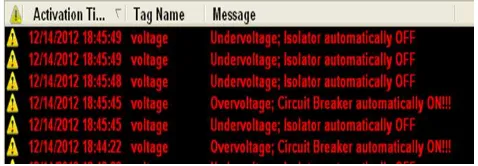
Generally, the operation start when the sensor sense the current/voltage at the substation either less than 240V or more than 240V, it detect as a fault. The program of RTU identifying the voltage less than 240V, it will represent under-voltage and process will go through the voltage transducer and analog sensor before RTU identifying the fault type. If the voltage is more than 240V, the circuit breaker will automatically detect over-voltage fault. The under-over-voltage and over-over-voltage data sampled in RTU memory before indicate at GUI interface. The GUI will present command from RTU and then display the type of fault and the action that have been taken. Besides, the GUI can also give a command to RTU e.g. to on/off the circuit breaker.
Figure 6: Alarm indicate fault and action
V. CONCLUSION
In this modern world, demand for electricity is in need continuously. Such this requirement is to be fulfilled every time. However, one cannot expect to get electricity every second in the every hour continuously. Electrical distribution system is where the electricity supply is received every time. Substations supply electricity to the distribution system includes [7]:
No proper protection system for the distribution system
No automation system for the distribution system
If fault occurs, it depends solely on human intervention, this practice takes long time and it involves the cost of intervention itself
Neural conductors are made of copper which are susceptible to thefts
If fault occurs to the system, the transformer must be disconnected otherwise over-voltages will result the transformer will be overheated and burned
All of the above problems can be solved by proposing non-expensive intelligent distribution automation system.
ACKNOWLEDGMENT
The authors would like to thank to the Ministry of Science, Technology and Innovation (MOSTI), Ministry of Higher Education (KPT), Government of Malaysia and the Universiti Teknikal Malaysia Melaka (UTeM) for the support and assistance given to this research.
REFERENCES
[1] Palak Parikh, “Distribution Automation System”, Ph.D. Scholar, Electrical and Computer Engineering Department, University of Western Ontario.
[2] B.L. Theraja et. all “A Textbook of Electrical Technology Vol.III, Transmission, Distribution and Utilization,” S. Chand & Co. Ltd., 2002. [3] Stuart A. Boyer, “SCADA Supervisory Control
and Data Acquisition,” 3rd Edition, ISA-The Instrumentation, System and Automation Society, 2004
[4] David Bailey, “SCADA for Industry,” Newnes, An imprint of Elsevier, Linacre House, Jordan Hill, Oxford 2003.
[5] Eng.Wael E. Matti and Dr. Jabir S.Aziz, “Design and implementation of general purpose RTU,” Global Journal of Researches in engineering electrical and electronic engineering, 2012 [6] IEEE Power Engineering Society, “Specification
and Analysis of Systems Used for Supervisory Control, Data Acquisition, and Automatic Control”, IEEE Std. C37.-1995, IEEE Standard Definition, New York, 1994, pp-12.
[7] Lee, Heung-Jae and Park, Y.M, “A Restoration Aid Expert System for Distribution Subsations”, IEEE Transactions on Power Delivery, 1996, Vol. 11, No. 4, pp 1.
[8] M.M.Ahmed, W.L.Soo, M.A.M Hanafiah and M.R.AGhani, “Customized FaultManagement System for Low Voltage (LV) Distribution Automation System”, Chapter of a book, Fault Detection, Intechweb.com,2010.
2013 IEEE 7th International Power Engineering and Optimization Conference (PEOCO2013), Langkawi, Malaysia. 3-4 June 2013
![Figure 1: Interconnection of distribution, control and communication system [2]](https://thumb-ap.123doks.com/thumbv2/123dok/530777.61367/1.612.328.550.594.674/figure-interconnection-distribution-control-communication.webp)
![Figure 3: Outgoing signal from RTU [3]](https://thumb-ap.123doks.com/thumbv2/123dok/530777.61367/2.612.326.562.66.286/figure-outgoing-signal-from-rtu.webp)
![Figure 5: ITIC (The Information Technology Industry Council) [6]](https://thumb-ap.123doks.com/thumbv2/123dok/530777.61367/3.612.326.549.184.447/figure-itic-information-technology-industry-council.webp)