UNIVERSITI TEKNIKAL MALAYSIA MELAKA
STUDY ON THE PARAMETERS EFFECT OF TOOL WEAR FOR
DIFFERENT CUTTING TOOL IN TURNING PROCESS
This report submitted in accordance with requirement of the Universiti Teknikal Malaysia Melaka (UTeM) for the Bachelor Degree of Manufacturing Engineering (Manufacturing
Process) with Honours.
by
NURULATIQAH BINTI ABDULLAH
FACULTY OF MANUFACTURING ENGINEERING
DECLARATION
I hereby, declared this report entitled “Study of the parameters effect of tool wear for different cutting tool in turning process” is the results of my own research except as cited in references.
Signature :
Author’s Name : UMMI NAZAHAH BINTI ROSLAN
APPROVAL
This report is submitted to the Faculty of Manufacturing Engineering of UTeM as a partial fulfillment of the requirements for the degree of Bachelor of Manufacturing Engineering
(Manufacturing Process) with Honours. The member of the supervisory committee is as follow:
1
CHAPTER I
INTRODUCTION
1.1 BACKGROUND
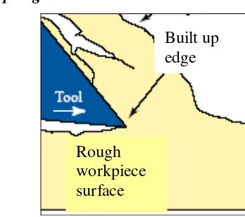
Austenitic stainless steel is a material from the grades of chromium-nickel steels which exhibiting a very high corrosion resistance and excellent mechanical properties. Austenitic stainless steels cannot be hardened by traditional heat treatment processes but they can be strengthened by cold working (Novak, 1978). AISI 304 steel is hard to machine. Machining operations of austenitic stainless steels are usually accompanied by a number of difficulties such as irregular wear and Built-Up-Edge (BUE) on the tool flank face and crater face respectively. The present of BUE will cause an increasing in tool wear rate and deterioration of the surface integrity of the work. The poor machinability of this material is usually accounted for some reasons such as having very low heat conductivity, high ductility, high tensile strength, high fracture toughness and high work hardening rate (Groover, 1990).
2
adhesion, abrasion, diffusion, oxidation and fatigue (Trent, 1991). Some authors affirm that the flank wear in carbide tools initially occurs due to abrasion as the wear progresses. High speed cutting always generates high temperature, which enhances diffusion and oxidation process of carbide tool (Venkatesh, 1980). The advantages of high speed machining are the ability to produce precise dimension, high productivity and good quality parts. Most of the heat generated was used to remove the chip while the temperature of cutting tools and work piece maintained at ambient temperature.
The quality of machined surface becomes more critical in view of very high demand to performance, lifetime and reliability. The components that used in automotive, aerospace and other industries were applied in highly stress and temperature. Hence, the surface integrity of machined component becomes more important because it could cause sudden fatigue failure. Therefore, further investigation in machined surface of hard steel components are highly required.
1.2 PROBLEM STATEMENT
3
affects the cutting tool characteristics differently. However, the machinist doesn’t know which cutter is appropriate for hard machining operations.
1.3 OBJECTIVES
To investigate the effect of cutting parameters (cutting speed, feed rate and depth
of cut) to the wear of tool.
To analyze the performance of the tool with different parameters given.
To propose the best cutting tool that can be used in machining of stainless steel
304.
1.4 SCOPE OF THE PROJECT
4
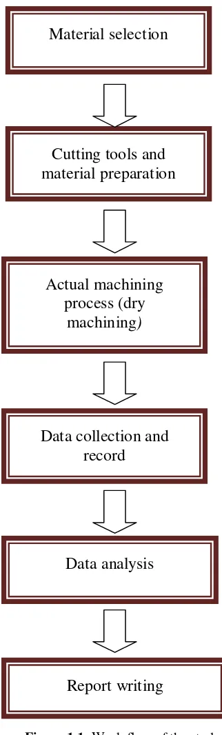
Toward the achievement of the objectives of the project, here is the outline of experimental that will be carried out to produce the result.
Figure 1.1: Work flow of the study Material selection
Cutting tools and materialpreparation
Actual machining process (dry
machining)
Data collection and record
Data analysis
5
CHAPTER II
LITERATURE REVIEW
The literature review is conducted to achieve the objectives of this research. It including the information of carbide tools used in turning, wear observation during turning operations, and life of the cutting tools itself. All of this formation is served as the guidelines in the course of the study.
2.1 INTRODUCTION
Machining is a process designed to change the size, shape, and surface of a material through removal of materials that could be achieved by straining the material to fracture or by thermal evaporation. There are many kinds of machining operations, each of which is capable of generating a certain part geometry and surface texture.
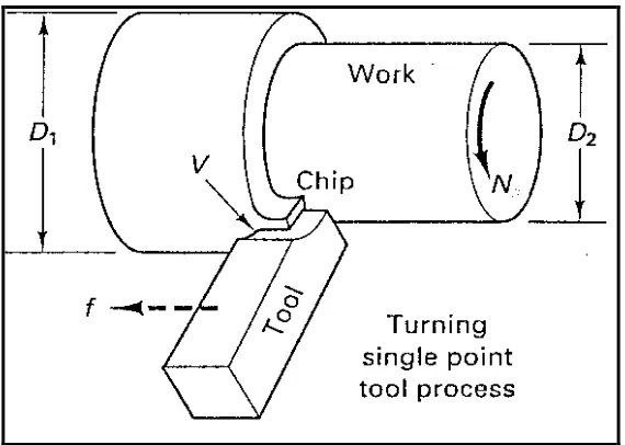
In turning, a cutting tool with a single cutting edge is used to remove material from a rotating workpiece to generate a cylindrical shape. The speed motion in turning is provided by the rotating workpart, and the feed motion is achieved by the cutting tool moving slowly in a direction parallel to the axis of rotation of the workpiece.
6
Figure 2.1: Basic Metal Cutting Theory
2.2 PHYSIC AND MECHANIC OF METAL CUTTING
Cutting processes are often necessary in order to impart the desired surface finish and dimensional accuracy to component. To achieve a good result in cutting processes, physic and mechanic of metal cutting are emphasis. A large number of variables have significant influence on the mechanics of chip formation in cutting operations. Commonly observed chip types are continuous, built up edge, discontinuous and segmented.
2.2.1 Physic Metal Cutting
7
2.2.1.1 Chip Formation
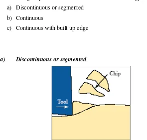
Metal cutting chips have been classified into three basic types (Steve and Albert, 1997): a) Discontinuous or segmented
b) Continuous
c) Continuous with built up edge
a) Discontinuous or segmented
Figure 2.2: Illustration of Discontinuous or segmented chip (Schneider, 1999)
Discontinuous or segmented chips are produced when brittle metal such as cast iron and hard bronze are cut or when some ductile metals are cut under poor cutting conditions. As the point of the cutting tool contacts the metals, some compression occurs, and the chip begins flowing along the chip tool interface. As more stress is applied to brittle metal by cutting action, the metal compresses until it reaches a point where rupture occurs and the chip separates from the unmachined portion. Generally, as a result of these ruptures, a poor surface is produced on the workpiece (Schneider, 1999).
8 i) Brittle work material.
ii) Small rake angle on the cutting tool iii) Large chip thickness
iv) Low cutting speed
v) Excessive machine chatter.
b) Continuous
Figure 2.3: Illustration of continuous chip (Schneider, 1999).
Continuous chip are usually formed with ductile materials at high cutting speed and high rake angles. The deformation of the material takes place along a narrow shear zone, the primary shear zone. Continuous chip may because of friction, develop a secondary shear zone at the tool chip interface. The secondary zone becomes thicker as tool chip friction increase.
9 (a) Ductile work material
(b) Small chip thickness (relatively fine feeds) (c) Sharp cutting tool angle
(d) A large rake angle on the cutting tool (e) High cutting speed
(f) Cutting tool and work kept cool by use of cutting fluids (g) A minimum of resistance to chip flow by:
i. A high polish on the cutting tool face
ii. Use of cutting fluids to prevent the formation of a built up edge iii. Use of cutting tool material such as cemented carbide, which have a
low coefficient of friction.
c) Continuous with built up edge
Figure 2.4: Illustration of continuous with built up edge (Schneider, 1999).
10
flow of chip along the chip tool interface, small particles of metal begin adhering to the edge of the cutting tool while the chip shear away.
As the cutting process continues, more particles adhere to the cutting tool, a larger buildup results, which affects the cutting action. The continuous chip with built up edge, as well as being the main cause of surface roughness, also shortens cutting tool life. When a cutting tool starts to dull, it creates a compressing action on the workpiece, which generally produced work hardened surface. These types of chip affect cutting tool life in two ways:
(a) The fragments of the built up edge abrade the tool flanks as they escape with the workpiece and chip.
(b) A cratering effect is caused a short distance back from the cutting edge where the chip contacts the tool face. As this cratering continues, it eventually extends closer to the cutting edge until fracture or breakdown occurs.
The factors responsible for continuous built up edge are: (a) Ductile material
(g) High friction at chip tool interface
11
The two main parameters influencing the chip morphology are the hardness of material and the cutting speed. That shows that the effect of the cutting speed and the hardness are interdependent; in fact, the chip formation is governed by more global physical quantity such as the generated energy, and by the consequent temperature. The chip formation mechanism based on the occurrence of a crack concerns very hard steels on account of their higher brittleness. Chip formation by cracking may occur with less hard steels but at higher cutting speeds, the embrittlement being induced by the kinetic of loading.
2.2.2 Mechanics Metal Cutting
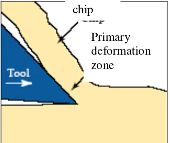
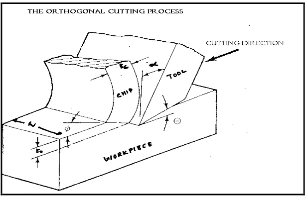
In general, machining is 3D-process for providing an understanding of mechanics of machining; the process is simplified into a 2D-process called as Orthogonal Cutting as shown in Figure 2.5. In orthogonal cutting, the workpiece is a flat plate (it can be a thin tube too) and is machined using a wedge-shaped tool with a rake angleof α and a relief angle of σ. The workpiece is moving at a cutting speed of V with a depth of cut to remove material. The width remains unaffected. An analysis based on the classical thin zone mechanics for materials that yield continuous chip with planar shear process (Merchant, 1989). The following assumptions were made:
i. The tool tip is sharp and no rubbing or ploughing occurs between the tool and workpiece.
ii. Plain strain conditions, such as there is no side spread and therefore the deformation is two dimensional.
12
Figure 2.5: The orthogonal cutting process
The resultant force on the chip applied at the shear plane is equal, opposite and collinear to the force applied which is the force applied to the chip at the tool-chip interface (Lapidge et al., 1997).
2.3 MACHINING PARAMETERS
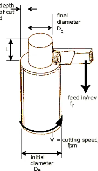
For a metal cutting process, there are three variable considered as a parameter in machining which is speed, feed and depth of cut. Other factors such as kind of material and type of tool have a large influence in machining, but these three are the ones we can change by adjusting the controls, right at the machine. These three of variable is also importance in influence metal removal rate and tool life.
2.3.1 Speed
13
feet) of the workpiece before the cut is started. It is expressed in surface feet per minute (sfpm) , and it refers only to the workpiece. Every different diameter on a workpiece will have a different cutting speed, even though the rotating speed remains the same (Michigan Technological University’s Turning Information Center).
2.3.2 Feed
Feed is refers to the cutting tool, and it is the rate at which the tool advances along its cutting path. The feed rate is directly related to the spindle speed and is expressed in inches (of tool advance) per revolution (of spindle).
2.3.3 Depth of Cut
14
Figure 2.6: Illustration of speed, feed and depth of cut
Below is a summary list of the terms used: Da = initial diameter
Db = final diameter
fr = feed (in/rev, in/cycle, in/min, in/tooth)
V= cutting speed
2.4 TOOL WEAR
15
Cutting tools are subjected to an extremely severe rubbing process. They are in metal to metal contact, between the chip and workpiece, under conditions of very high stress at high temperature. The situation is further aggravated due to the existence of extreme stress and temperature gradients near the surface of the tool. During cutting, cutting tools remove the material from the component to achieve the required shape, dimension and surface roughness. However, wears are occurring during the cutting action, and it will result in the failure of the cutting tool. When the tool wear reach certain extent, the tool or edge change has to be replaced to guarantee the ordinary cutting action.
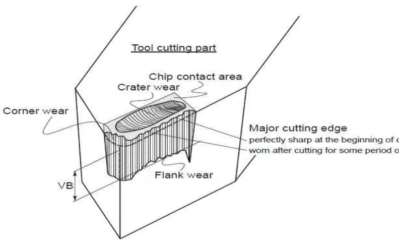
2.5 TOOL WEAR PHENOMENA
Figure 2.7 : Tool wear phenomena
16
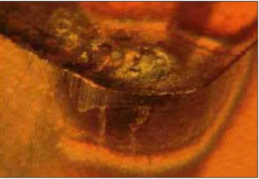
2.5.1 Crater wear (Rake Face Wear)
Crater wear occurred when chip flows away on the rake face, results in the severe friction between the chip and rake face, and leave a scar on the rake face which usually parallels to the major cutting edge. The crater wear could increase the working rake angle and reduce the cutting force, but it will also weaken the strength of the cutting edge. Crater wear on the chip face can be due to abrasive and diffusion wear mechanisms. The crater is formed through tool material being removed from chip face either by the hard particle grinding action or at the hottest part of the chip face through the diffusive action between the chip and tool material. Hardness, hot hardness and minimum affinity between materials minimize the tendency for crater wear. Excessive crater wear changes the geometry of the edge and can deteriorate chip formation, change cutting force directions and also weaken the edge.
Figure 2.8 : Crater wear (source : SANDVIK Coromant)
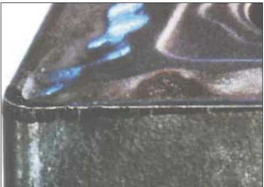
2.5.2 Clearance (flank) Surface Wear
17
tool or by tracking the change in size of the tool or machined part. Flank wear can be measured by using the average and maximum wear land size VB and VBmax.
Figure 2.9 : Flank wear (source : SANDVIK Coromant)
18
Figure 2.10 : Variation of flank wear rate with cutting time,
2.5.2.1Typical stage of tool wear in normal cutting situation
1. Initial wear region:
It is caused by micro-cracking, surface oxidation and carbon loss layer, as well as microroughness at the cutting tool tip in tool grinding (manufacturing). For the new cutting edge, due to the small contact area and high contact pressure, it will result in high wear rate. The initial wear size normally.is VB = 0.05-0.1mm
2. Steady wear region
19
3. Severe wear:
When the wear size increases to a critical value, the surface roughness of the machined surface decreased. When the cutting force and temperature increase rapidly, the wear rate increases. Then the tool loses its cutting ability. In practice, this region of wear should be avoided.
2.5.3 Notch wear (Boundary Wear)
This is a special type of combined flank and rake face wear which occurs adjacent to the point where the major cutting edge intersects the work surface. The grooving at the outer edge of the wear land is an indication of a hard or abrasive skin on the work material. Such a skin may develop during the first machine pass over a forging, casting or hot-rolled workpiece. It is also common in machining of materials with high work-hardening characteristics, including many stainless steels and heat-resistant nickel or chromium alloys.
20
2.5.4 Chipping
Chipping of the tool, as the name implies, involves removal of relatively large discrete particles of tool material. Tools subjected to discontinuous cutting conditions are particularly intended to chipping. Built-up edge formation also has a tendency to promote tool chipping. A built-up edge is never completely stable, but it periodically breaks off. Each time some of the built-up material is removed it may take with it a lump (piece) of tool edge.
Figure 2.11: Chipping of the cutting edge (source : SANDVIK Coromant)
2.5.5 Plastic deformation