UNIVERSITI TEKNIKAL MALAYSIA MELAKA
THE EFFECT OF DIFFERENT CUTTING TOOL MATERIAL
TO THE SURFACE FINISH OF D2 TOOL STEEL IN
DRILLING PROCESS
This report is submitted in accordance with the requirement of the Universiti Teknikal Malaysia Melaka (UTeM) for the Bachelor Degree of Manufacturing
Engineering Technology (Process and Technology) Honours
by
NURAFIFAH BINTI MASIRON B071210186
930116-01-6022
UNIVERSITI TEKNIKAL MALAYSIA MELAKA
BORANG PENGESAHAN STATUS LAPORAN PROJEK SARJANA MUDA
TAJUK: The Effect of Different Cutting Tool Material to the Surface Finish of D2 Tool Steel in Drilling Process
SESI PENGAJIAN:2015/16 Semester 1
SayaNURAFIFAH BINTI MASIRON
mengakumembenarkanLaporan PSM inidisimpan di PerpustakaanUniversitiTeknikal Malaysia Melaka (UTeM) dengansyarat-syaratkegunaansepertiberikut:
1. Laporan PSM adalah hak milik Universiti Teknikal Malaysia Melaka dan penulis. 2. Perpustakaan Universiti Teknikal Malaysia Melaka dibenarkan membuat salinan
untuk tujuan pengajian sahaja dengan izin penulis.
3. Perpustakaan dibenarkan membuat salinan laporan PSM ini sebagai bahan pertukaran antara institusi pengajian tinggi.
4. **Silatandakan ( ) sebagaimana yang termaktubdalam AKTA RAHSIA RASMI 1972)
NO. 7 Jalan Berlian 33,
Taman Cahaya Masai,
DECLARATION
I hereby, declared this report entitled “The Effect of Different Cutting Tool Material to the Surface Finish of D2 Tool Steel in Drilling Process” is the results of my own
research except as cited in references.
Signature :………
Name :Nurafifah Binti Masiron
v
APPROVAL
This report is submitted to the Faculty of Manufacturing Engineering Technology of UTeM as a partial fulfillment of the requirements for the degree of Bachelor of Engineering Technology (Process and technology) (Hons.). The member of the supervisory is as follow:
vi
ABSTRACT
vii
ABSTRAK
viii
DEDICATIONS
To my beloved parents En Masiron Bin Kibok and Pn Aesah Binti Masdar, this is for you. Thank you for all your sacrifice. I love u so much mom,dad, angah, kak de and
ix
ACKNOWLEDGMENTS
First of all, I would like to express my gratitude to all those who gave me the possibility to complete this project. I am deeply indebted whose help, stimulating suggestions and encouragement helped us in all the time of this project among this report in progress until done.
Big thanks to my academic supervisor, Mr Mohd Hairizal Bin Osman. He has been helping me out in the academic field including finishing this technical report. And not to forget to the Department of Process Engineering staff and lecturers and other UTeM staffs and lecturer and who had been involving directly or indirectly though out this process. Without their help and support, it would have been tougher for me to finish my project.
And last but not least, I would like to express thousands thanks to my family and friends which always give their support and advice for me. They have contributed for ideas, critics, opinions, and advices during the training period and finalizing my report.
x
TABLE OF CONTENTS
DECLARATION... iv
APPROVAL...v
ABSTRACT...vi
ABSTRAK...vii
DEDICATIONS...viii
ACKNOWLEDGMENTS... ix
TABLE OF CONTENTS...x
LIST OF FIGURES... xiii
LIST OF TABLE... xiv
CHAPTER 1...1
1.0 Introduction... 1
1.1 Background...1
1.2 Problem Statement...3
1.3 Project Objective... 3
1.4 Project Contributions...3
1.5 Project scope...4
CHAPTER 2...5
2.0 Introduction... 5
xi
2.1.1 Characteristics and Design Consideration for Drilling... 7
2.2 CNC Milling Machine for Drilling Machine...7
2.2.1 Related Cutting Parameter... 8
2.2.2 Application of Coolant...9
2.2.3 Various Types of Drilling Tool...9
2.2.4 Coating of Drilling Tool...11
2.2.4.1 Coated of Titanium Nitride (TiN)...11
2.2.4.2 Coated of Titanium Carbon Nitride (TiCN)... 12
2.3 AISI D2 Tool Steel...13
2.3.1 Codes and Standards of AISI... 14
2.3.2 Types of Tool and Die Steels...14
2.3.3 Processing and Service Characteristics of Common Tool and Die Steels...15
2.4 Effect of various Cutting Parameter to the Surface Finish...17
CHAPTER 3...20
3.0 Introduction... 20
3.1 Flowchart...20
3.2 Experimental Setup... 22
3.2.1 AISI D2 Tool Steel...22
3.2.1.1 Composition of AISI D2 Tool Steel... 23
3.2.2 Drilling Tool...24
3.2.3 Parameter...27
3.2.4 Taguchi Method... 27
xii
3.2.6 Surface Roughness Tester Mitutoyo SJ-410...32
3.2.6.1 Standard Procedure for Surface Roughness Testing...34
CHAPTER 4...36
4.0 Introduction... 36
4.1 Experimental Results...36
4.1.1 Result of Surface Finish...36
4.2 Taguchi Analysis, S/N ratio and Mean plot graph... 38
4.3 Analysis of Variance (ANOVA)... 42
4.4 Taguchi Analysis Predicted...43
4.5 Confirmation Test...44
CHAPTER 5...45
5.0 Introduction... 45
5.1 Summary of Research...45
5.2 Achievement of Research Objectives...46
5.3 Suggestion for Future Work... 46
REFERENCES...47
xiii
LIST OF FIGURES
Figure 2.1: Illustrates about the common twist drill...6
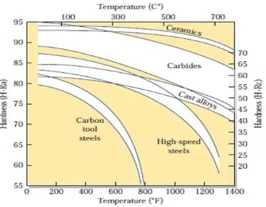
Figure 2.2 : Hardness of various cutting tool materials (2012)... 10
Figure 2.3 : Drill Bit of High Speed Steel coated with Titanium Nitride (TiN),...12
Figure 2.4 : Drill Bit of High Speed Steel coated with Titanium Carbon Nitride (TiCN), (Kalpakjian and Schmid, 2010)... 13
Figure 2.5 : An example table of Surface Finish Values with S/N Ratio (Nalawade and Shinde, 2015)... 18
Figure 2.6 : Effect of drilling parameter on Surface Finish (S/N Ratio),... 19
Figure 3.1: Flowchart...21
Figure 3.2 : Squaring process by using conventional milling machine...22
Figure 3.3 : Work piece after finish the squaring process... 23
Figure 3.4 : High speed steel drill bit... 25
Figure 3.5 : Tool Master Quadra (CNC Laboratory, FTK Factory 1)...26
Figure 3.6 : Guidance of Taguchi Orthogonal Array Design... 28
Figure 3.7 : CNC Milling Machine DMC 635 V ecoline...30
Figure 3.8 : Mitutoyo Surface Roughness Tester, SJ-410...33
Figure 4.1 : Smaller is better characteristics equation...38
Figure 4.2 : Main effects plot for Means... 39
Figure 4.3 : Main effects plot for S/N ratios...39
Figure 4.4 : Taguchi Analysis in Minitab software and for signal to noise...41
xiv
LIST OF TABLE
Table 2.1: Recommendation parameter (Nalawade and Shinde,2015)... 8
Table 2.2 : Related specifications of AISI codes and standard terms (Global Metals, 2015)...14
Table 2.3 : Basic type of Tool and Die Steels (Kalpajikan, 2010)... 15
Table 2.4 : Processing and Service characteristics of Common Tool and Die Steels (Kalpakjian ,2010)... 16
Table 3.1 : Chemical composition of AISI D2 Tool Steel work piece...24
Table 3.2 : Dimensional properties of drilling tool... 25
Table 3.3 : Diameter and length value of each drill bit... 26
Table 3.4 : The selection parameter...27
Table 3.5 : Manual Taguchi Orthogonal Array Design...28
Table 3.6 : Taguchi Orthogonal Array Design by using Minitab...29
Table 3.7 : The specifications of DMC 635 Veroline... 30
Table 3.8 : Sequencing drilling holes in the drilling process... 31
Table 3.9 : Specification of Surface Roughness Tester...32
Table 3.10 : Procedure of using Mitutoyo Surface Roughness Tester SJ-410... 34
Table 4.1 : Response table for Arithmetical mean deviation of the roughness profile, Ra, readings and average... 37
Table 4.2 : Results of the analysis of variance... 42
1
CHAPTER 1
INTRODUCTION
1.0 Introduction
This chapter will discuss briefly the project flow from introduction, project
background, problems statement of project, project objective, project scope and the flow chart of the project. This project title is a Cutting Parameter Optimization for Surface Finish in Drilling Process of AISI D2 Tool Steel using Taguchi method. The existing method that is currently used is Taguchi method. This project will focuses on all effects of parameters on surface finish in drilling operation with coolant. The parameter that will be use are spindle speed, feed rate and type of drill bit. This part of the report will explain further about the purpose of the project.
1.1 Background
2
Coolant lubricants can improve the machinability of the work piece, increase productivity and extend tool life by reducing tool wear. Besides, coolant is very important in machining processes to reduce the effects of friction and also make the surface roughness become smooth. The type of coolant that will use in CNC Milling machine is lubricant with a grade of ECOCOOL 6210 IT. The size of the block AISI D2 Tool Steel 100mm x 100mm with thickness of 40mm is used as a base of the drilling process. AISI D2 Tool Steel is hardened in air with a low order of movement, high corrosion resistance when polished, very high wear resistance and toughness. AISI D2 Tool Steel with a hardness of 45-68 HRC was hard machined (Takacs and Farkas, 2014).
In this project, there are 3 types of drilling tool that had be selected to use which is High Speed Steel (HSS) coated with Titanium Nitride (TiN), HSS coated with Titanium Carbon Nitride (TiCN) and HSS uncoated. The diameter of all these drilling tool was selected as 10mm. High Speed Steel is a cutting tool material that had been used in drilling, milling, turning, threading, boring, broaching, gear cutting and other types of machining process. High-speed tool steels are used for most of the common types of cutting tools including single-point lathe tools, drills, reamers, taps, milling cutters, end mills, hobs, saws and broaches (Bayer et al, 1989).
3 1.2 Problem Statement
The problem for this project is the material of AISI D2 Tool Steel is hard to machine because the hardness ranging is about 54-61 HRC. HRC is stand for Rockwell C hardness which is one of the metallurgy testing. A popular grade for toolmakers, D2 is used in a wide variety of tool making applications (Rob and Duncan, 2015). The blanking dies and punches for sheet in stainless steel, brass, copper, zinc and hard abrasive materials are the typical applications for AISI D2 Tool Steel.
1.3 Project Objective
The following are the objective of this project;
1) To study the effects of various cutting parameters to the surface finish of AISI D2 Tool Steel in drilling process.
2) To analyze the optimum parameter for drilling process for the better surface finish.
1.4 Project Contributions
4 1.5 Project scope
5
CHAPTER 2
LITERATURE REVIEW
2.0 Introduction
This literature review is presented thoroughly on the issue that is related with the Cutting Parameter Optimization for surface Finish in Drilling Process of AISI D2 Tool Steel using Taguchi method. The literature review provides background information and thus to determine the objectives of the present project. It will give part in order to get that information.
2.1 Drilling Process
6
The Drilling process that involves the creation of holes that are right circular cylinders and it is reaching a most typically by using a twist drill. The Figure 1 below shows an illustration about how the common twist drill cut and produces a cross section of a hole. Based on the Figure 1, the drilling tool is embedded inside the work piece and the chips must exit by the flutes to the outside of the drilling tool. Therefore, it making the cooling is more difficult. The drill cutting area can be flooded, coolant or cutting fluid can be applied and can be delivered through the drill bit shaft.
7
2.1.1 Characteristics and Design Consideration for Drilling
Below are the characteristics of drilling operation that set it apart from other metal cutting operations (Drilling Characteristics, 2015).
i. The chips must exit from the hole to the outside of the drilling tool that created by the cutting.
ii. If the chips are large or continuous, the problem can cause when the chip exit. iii. The drill can wander when enter the work piece and for deep holes.
iv. Coolant or cutting fluid has to be delivered through the drill shaft to the cutting front for deep holes in a large work pieces.
v. The drilling on a drill press is the most likely to be performed by someone who is not a machinist.
2.2 CNC Milling Machine for Drilling Machine
The meaning of CNC is a Computer Numerical Control where is a computer converts the design that produced by Computer Aided Design software into numbers. The drilling process is performing on a CNC milling machine of DMC 635 Veroline with a controller by a Siemens 840. The earliest precedent to CNC machines may be the Jacquard loom, a mechanical process invented in 1801 by Joseph Marie Jacquard to simplify the process of manufacturing complex textile patterns. (Sammarco, 2011).
8 2.2.1 Related Cutting Parameter
To obtain the maximum machining rate as well as minimum machining cost, the cutting parameter is very important factor. The high productivity and high material removal rate for drilling process can be achieve by changing the process parameters such as drilling diameters, cutting speed, feed rate and many more. The drilling performance like tool life and material rate removal also can improve. Study on the influence of cutting parameters such as cutting velocity, feed rate, cutting time on drilling metal – matrix composites and concluded that interaction of cutting speed/feed is the most important factor contributing towards surface roughness of drilled holes (J Paulo davim, 2003).
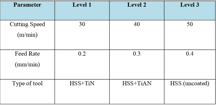
According to Nalawade and Shinde (2015), the 3 parameters of Cutting Speed, Feed rate and type of tool with 3 levels as shown in the table below is selected as 3 parameters for optimization of surface finish and using the set smaller is better for optimization of setting of parameters for achieving higher surface finish.
Table 2.1: Recommendation parameter (Nalawade and Shinde,2015)
Parameter Level 1 Level 2 Level 3
Cutting Speed
9 2.2.2 Application of Coolant
Cutting fluids are widely be use to optimize the process of machining operations such as turning, drilling, boring, grinding, milling, drawing, stamping, and sawing. The benefits of cutting fluid such as extended tool life, increased speeds and feeds, tighter tolerance capability, and improved finish will provide by the proper selection of cutting fluid. It has seen extensive use and has commonly been viewed as a required addition to high productivity and high quality machining operations. (Adler et al, 2006).
Coolant and lubricants will make the surface finish become smoother and widely used in industries for metal cutting operations. There also can improve the machinability of the work piece, increase productivity, make the tool life is longer by reducing tool wear and flush away the chips that are produced during the machining. Depending on the type of machining operation, the cutting fluid needed may a coolant, a lubricant or both (Kalpakjian 2010).
2.2.3 Various Types of Drilling Tool
10
There are the general characteristic of all high speed steel: i. Excellent toughness
ii. Resistance to fracture
iii. Wide range of roughing and finishing cuts iv. High working hardness
11 2.2.4 Coating of Drilling Tool
Coating is a layer of material deposited onto a substrate to increase the surface properties for corrosion and wear protection. The coating of tool is very helpful to extend the lifetime of tools. The effectiveness of coatings is be improved by the hardness, toughness and high thermal conductivity of the substrate. There are several factors that affecting the choice of a coating which is service of environment, life expectancy, substrate material compatibility, component of shape and size also the cost. Coated tools can have lives 10 times longer than those of uncoated tools, allowing for high cutting speeds and thus reducing both the time required for machining operations and production costs (Kalpakjian and Schmid, 2010).
There are several type of properties for coated tools: i. Lower friction
ii. Higher adhesion
iii. Higher resistance to wear and cracking iv. Acting as a diffusion barrier
v. Higher hot hardness and impact resistance
2.2.4.1 Coated of Titanium Nitride (TiN)