UNIVERSITI TEKNIKAL MALAYSIA MELAKA
CUTTING TOOL PARAMETER OPTIMIZATION FOR
SURFACE ROUGHNESS OF MILD STEEL MATERIAL USING
TAGUCHI METHOD
This report is submitted in accordance with the requirement of the
UniversitiTeknikal Malaysia Melaka (UTeM) for the Bachelor of Manufacturing Engineering Technology (Process and Technology) With Honours
by
AFEEQA BT ABD GHANI
B071210235
911006-07-5482
UNIVERSITI TEKNIKAL MALAYSIA MELAKA
BORANG PENGESAHAN STATUS LAPORAN PROJEK SARJANA MUDA
TAJUK: CUTTING TOOL PARAMETER OPTIMIZATION FOR SURFACE ROUGHNESS OF MILD STEEL MATERIAL USING TAGUCHI METHOD
SESI PENGAJIAN: 2014/15 Semester 2
Saya AFEEQA BT ABD GHANI
mengakumembenarkanLaporan PSM inidisimpan di PerpustakaanUniversitiTeknikal Malaysia Melaka (UTeM) dengansyarat-syaratkegunaansepertiberikut:
1. Laporan PSM adalah hak milik Universiti Teknikal Malaysia Melaka dan penulis. 2. Perpustakaan Universiti Teknikal Malaysia Melaka dibenarkan membuat salinan
untuk tujuan pengajian sahaja dengan izin penulis.
3. Perpustakaan dibenarkan membuat salinan laporan PSM ini sebagai bahan pertukaran antara institusi pengajian tinggi.
4. **Silatandakan ( ) sebagaimana yang termaktubdalam AKTA RAHSIA RASMI 1972)
** JikaLaporan PSM ini SULIT at au TERHAD, silalampirkansurat daripadapihakberkuasa/ organisasiberkenaandenganmenyat akansekalisebabdant em
i
DECLARATION
I hereby, declared this report entitled “Cutting Tool Parameter Optimization for
Surface Roughness of Mild Steel Material Using Taguchi Method” is the results of
my own research except as cited in references.
Signature :………
Name : AFEEQA BT ABD GHANI
ii
APPROVAL
This report is submitted to the Faculty of Engineering Technology of UTeM as a partial fulfillment of the requirements for the Bachelor of Manufacturing Engineering Technology (Process and Technology) With Honours. The member of the supervisory is as follow:
iii
ABSTRACT
iv
ABSTRAK
Laporaniniadalahhasildaripadaeksperimenuntukmengkajikekasaranpermukaa nsemasapengilanganakhirdaripadakelulilembut
.Denganmenggunakanmesinpemotong automatic (CNC Milling) 3paksi
untukmengoptimumkanpenetapanmemotong parameter kadarsuapan
,kelajuangelendongdankedalamanpemotonganpadakekasaranpermukaansemasa proses pemotonganpadapermukaanbahankelulilembut AISI 1050 sebagaibahankerja. Secaraamnyakadarnilaipemotonganakanmempengaruhipadakekasaranpermukaandala
moperasipemotonganakhir .Untukmeramalkankekasaranpermukaan,
RekabentukEksperimenuntukKaedah Taguchi denganmenggunakanperisian
MINITAB 17 untukmengiradata yang akandiperolehi.
Nisbahisyaratbunyiuntuktelahdigunakanuntukmengkajiciri-ciriprestasidalam CNC
Milling Machine.Analisisjugamenunjukkanbahawanilai-nilai yang
diramalkandannilai-nilaidikirasangatrapat , yang jelasmenunjukkanbahawa model
yang disusunolehkaedah Taguchi
v
DEDICATIONS
To my beloved parents, my siblings, supervisor and all members that help me to
vi
ACKNOWLEDGMENTS
Alhamdulillah. Thank to Allah for giving me the strength and patience to complete this experiment. I would like to thanks to my family for their support given in order for me to complete this final project thesis with successfully. Then, I would like to express my deepest appreciation to Mr.Salleh bin Aboo Hassan as my supervisor because conduct me to analyse this experiment from the beginning to the end. Teach me about the Taguchi Method till understand the method.I will never forget his guidance, advice and motivation that he have given to me.
vii
2.1 CNC Milling Machine ... 4
2.2 End Milling ... 5
2.3 Cutting Tools ... 5
2.3.1 High Speed Steel and Carbide... 6
2.4 Machining Parameter ... 7
viii
2.4.3 Depth of Cut ... 8
2.5 Surface Roughness ... 9
2.5.1 Surface Finish Parameter ... 11
2.6 Material Overview ... 12
2.7 Taguchi Method ... 13
CHAPTER 3 ... 15
3.0 Introduction ... 15
3.1 Flow Chart ... 16
3.2 Apparatus Preparation use in Experiment ... 17
3.2.1 Material ... 17
3.2.2 Machine (CNC Milling Machine) ... 17
3.2.3 Tool (Facing) ... 18
3.3 Machining Process ... 19
3.3.1 Sample Preparation ... 19
3.3.2 Measuring Surface Roughness ... 20
3.3.3 Measurement Flow Chart ... 22
3.4 Cutting Parameter Setup ... 22
3.4.1 Parameter Setting ... 23
3.5 Taguchi Method Analysis ... 23
3.6 Design of Experiment (DOE) Analysis ... 25
3.6.1 DOE matrix ... 25
ix
4.0 Introduction ... 27
4.1 Result of the Experiment ... 27
4.1.1 Factor and Level ... 28
4.1.2 Taguchi Analysis ... 29
4.1.3 Optimum Machining Parameter ... 37
4.2 Discussion of the Result ... 38
CHAPTER 5 ... 41
5.0 Conclusion of the Result ... 41
5.1 Recommendation ... 42
APPENDIX A ... 43
APPENDIX B ………..51
x
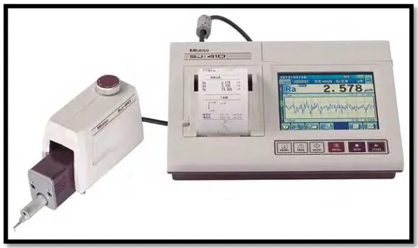
Figure 1.1: Mitutoyo Surface Roughness Tester... 3
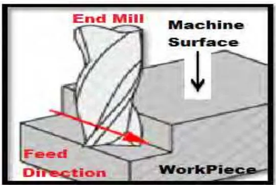
Figure 2.1: Cutting parameter of end mill ... 7
Figure 2.2: Machining Operation ... 10
Figure 3.1 : Experiment Flow Chart ... 16
Figure 3.2 : CNC Machine DMC 635 v eco line ... 18
Figure 3.3 End Mill Tool ... 19
Figure 3.4: Workpiece Dimension ... 20
Figure 3.5: Mitutoyo SJ-410 ... 20
Figure 3.6: Basic Operation Surface Roughness... 22
Figure 3.7: Array Selector ... 24
Figure 4.1: The Result After Machining specimen 1 ... 31
Figure 4.2: Result after Machining Specimen 2 ... 32
Figure 4.3: Main Effect plot for Means ... 34
xi
LIST OF TABLE
Table 2.1: Parameter and level of Mild Steel material ... 7
Table 2.2: Typical way to Obtain Syrface Roughness ... 11
Table 2.3: The element in Mild Steel AISI 1050 ... 12
Table 2.4: The Properties of Mild Steel ... 13
Table 3.1: The specification of CNC machine DMC 635v eco line ... 18
Table 3.2: The characteristic of the Mitutoyo SJ-410 ... 21
Table 3.3: Typical Way to Obtain Surface Roughness ... 21
Table 3.4: Experimental Conditions ... 23
Table 3.5: Signal to Noise Ratio Calculation ... 24
Table 3.6: Design Scheme of Experiment of Parameter and Levels... 24
Table 3.7: Orthogonal Array for Taguchi Method ... 25
Table 3.8: Taguchi Method Arrangement ... 25
Table 4.1 : Design Sheme of Parameter and Levels ... 28
Table 4.2: Experiment Factor and Level Parameter... 28
Table 4.3 : Result Surface Roughness Speciment 1 ... 30
Table 4.4: Result Surface Roughness for Specimen 2 ... 31
Table 4.5: Value Mean and Standard deviation in Sample T-test ... 32
Table 4.6: Result of P-value ... 32
Table 4.7: Result Surface Roughness... 32
Table 4.8: Result Experimental values and SN Ratio ... 33
Table 4.9: Response Table for Means ... 35
Table 4.10 Response Table for S/N Ratio (Smaller is Better) ... 37
Table 4.11: Optimum machining parameter ... 37
1
CHAPTER 1
INTRODUCTION
1.0 Background Project
This project is study parameter of cutting which is spindle speed, feed rate and depth of cut on surface roughness because surface roughness is one of the important factors for evaluating work piece quality during the machining process. This is because the quality of surface roughness affects the functional characteristics of the work piece such as compatibility, fatigue resistance and surface friction. The material used was Mild Steel by using high speed milling CNC machine. Milling is the most paramount metal abstracting process for manufacturing the different mechanical components.
2
According to (Meena, 2011). Surface roughness is one of the important factors for evaluating work piece quality during the machining process because the quality of surface roughness affects the functional characteristics of the work piece such as compatibility, fatigue resistance and surface friction. The factors that affect the surface roughness during the cessation milling process include implement geometry, aliment rate, depth of cut and cutting speed. Several researchers have studied the cessation milling process in the recent years.
The Taguchi optimization method was used for low surface roughness value in terms of cutting parameters in the CNC face milling of mild steel material (Bagci E, Aykut S. A 2006). While, Taguchi method will used for optimization of surface roughness in face milling of hardened steel in terms of cutting parameters.( Ghani JA, Choudhury I.A,2004). The Taguchi optimization methodologies to optimize the finishing parameter in CNC milling machining use mild steel and tool is high speed steel
1.1 Problem Statement
3
Figure 1.1: Mitutoyo Surface Roughness Tester
1.2 Research Objective
1. To determine the effect of spindle speed, feed rate and cutting speed on surface roughness during face milling process of Mild Steel workpiece.
4
CHAPTER 2
LITERATURE RIVIEW
2.0 Introduction
Machining is any of various processes in which a piece of raw material is cut into a desired final shape and size by a controlled material-removal process. Machining is divided in many sections like drilling, turning, milling, grinding, chip formation and which are capable of generating a certain part geometry and surface texture. In milling, a rotating tool with multiple cutting edges is moved slowly relative to the material to generate a plane or straight surface. The direction of the feed motion is perpendicular to the tool's axis of rotation. The speed motion is provided by the rotating milling cutter. The two basic forms of milling are peripheral milling and face milling. In peripheral milling, the axis of cutter rotation is parallel to the work piece surface (Kalpakjian and Schmid, 2013). Meanwhile, for face milling operations of cutter is perpendicular to the workpieces surface (Kalpakjian and Schmid, 2013). Face milling process is basically used to remove the upper surface of work pieces and commonly used for roughing process. In end milling process it is as same as face milling but, it is capable to produces various profile and curves surfaces.
2.1 CNC Milling Machine
5
spinning cutting tool. CNC machine is widely used in industry due to versatile capability to perform several processes such as boring, drilling, and facing or others. This machining using G-code n M-code as instruction programmed command the machine. The type of CNC milling that were used for this project is 3 axis machines (x- axis move horizontal, y-axis move transversely, z-axis moves vertically). Milling process is influent by certain parameter such as spindle speed and feed rate. Spindle speed can be defined as the speed that the material moves past the cutting edge of the tool. Meanwhile feed rate can be defined as the velocity at which the cutter is feed, that the cutting tool advances against the workpiece.
2.2 End Milling
The end milling cutter usually rotates on vertical axis or perpendicular to the workpiece surface. End milling is important and commonly used for milling operational due to versatility and capability to produce various type of profile and curved surface. The size of end milling cutter is usually straight shank or small cutter size other than that is tapered shank or lager size. The end milling cutter also usually made from carbide or high-speed steel. (Kalpakjian&schmid, 2010). The common type of end milling cutting tool is made of two flutes or four flutes.
2.3 Cutting Tools
6 2.3.1 High Speed Steel and Carbide
The two materials from which most cutting tools are made are carbide and high speed steel (HSS). While there are a vast number of classifications and metallurgical variations within each material, the most common grades used for rotary cutting tools such as engraving cutters are C-2 micro grain carbide and M2 HSS.
Carbide is an extremely hard and abrasion resistant material and is recommended for most typical engraving applications. While it is slightly more expensive than HSS, it can out last it by a factor of 5-10 times depending on the application. It can be used effectively both on plastic and metal and is the most cost-effective choice of engraving tools.
While HSS doesn't have the wear and life characteristics of carbide, it does tend to be more resilient and less brittle and is the best choice for deep cuts with small tip sizes in harder materials. Engraving seal dies which are typically done to a depth of .035"-.040" with a .007"-.010" tip is a good example.
One consideration in selecting which type of tool to be used is whether or not you do your own sharpening. Carbide tools last a longer time before becoming dull, but are more difficult to reshape. Achieving a perfect cutting edge requires the usage of a properly dressed and trued diamond grinding wheel of between 400 and 600 grit.
7
In getting the best result in milling operations, the parameter have to be specified in term of cutting speed, feed rate, and depth of cut. Based on Alauddin et al. (1997), with increase in the cutting speed of machining, the feed, and the depth of cut will simultaneously decrease the life of cutting tool during machining operation. There are several factors that also affect the tool life during machining which is type of lubricant, cutting forces and type of tool material. As shown in Table 2.1 the parameter and level of Mild Steel material. The Figure 2.1 is shown the machining direction process that running.
Figure 2.1: Cutting parameter of end mill
Table 2.1: Parameter and level of Mild Steel material
Control parameters Level Observed Value
1 2 3
Low Medium High
Spindle speed(rpm) 1000 1500 2000 1. Surface
Roughness (Ra)
Feed Rate(mm/min) 300 400 500
8 2.4.1 Spindle Speed
Spindle Speed, (rpm) is defined as the surface speed at diameter of the cutter rotating moving past a work piece (Kalpakjian, 2013). High cutting temperature and difficult chip disposal are two main problems encountered in high-speed face milling of Mild Steel. It is additionally inferred that there exists a proper scope of cutting speed in face milling of Mild Steel by cemented carbide tools. Actually, sustain does not have a critical impact for both sorts of milling operations (Liao et al., 2008). The speed is between the tool and workpiece in the main direction of cutting.
2.4.2 Feed Rate
Feed rate (mm/min) is the distance, in which the tool is moving or “feed”, through the work piece makes one finish revolution, divided by the number of effective cutting edges on the tool. Based on Ozel et al. (2007), at the lowest Feed Rate and the highest cutting speed it will produce the best of surface roughness. Generally the unit of Feed Rate is given in mm/min. “If you reduce your FeedRate too much relative to spindle speed, you will soon cause your cutter flutes to start "rubbing" or "burnishing" the workpiece instead of shearing or cutting chips.”(Ghani, J.A., Choudhury, I.A). Then, reduce feed rates while keeping the spindle speed up lightens the chip load and leads to a nice surface finish
2.4.3 Depth of Cut
9
associated with a better surface and for a long tool life.
2.5 Surface Roughness
10
Figure 2.2: Machining Operation
According to Liao (2007), in machining process, the common parameters that affect the surface roughness are Cutting Speed, Feed Rateand Depth of Cut. Based on Liao et al. (2007), the milling parameters of feed rate and method have significant affected on quality of surface roughness and they discover that the quality of surface roughness increased by increasing the Feed Rate. There are several factors that contradict the Feed Rate in affecting the surface roughness where high cutting speed will reduced the value of surface roughness. The previous research by Ozcelik and Bayramoglu (2006), the cutting parameter is the important part in producing a minimum surface roughness and long tool life. The minimum surface roughness was obtained when the cutting parameters was set at the lowest of feed rate and highest cutting speed (Ozel et al., 2007). The differences of machining process parameters will impact the quality and specifications of the products surface. At the same time the result of the higher surface roughness can affect the product performance in terms of friction, durability, operating noise and energy consumption.
11
technology, design and also in business field. (kalpakjian&Schmid, 2010).
2.5.1 Surface Finish Parameter
The surface finish may specify in several of machining operations. Ra, Ry, Rz means the value obtained by the following formula and expressed in micrometre (µm) when sampling only the reference length from the roughness curve in the direction of the mean line, taking X-axis in the direction of mean line and Y-axis in the direction of longitudinal magnification of this sampled part. Table 2.2 shows the typical way to obtain surface roughness which is Arithmetical mean roughness (Ra), Maximum peak (Ry) and Ten-point mean roughness (Rz).
Table 2.2: Typical way to Obtain Syrface Roughness
Typical way to obtain surface roughness
Arithmetical mean roughness (Ra)