AUTOMATED INTELLIGENT DRAWER OR LOCKER SECURITY SYSTEM
Shafizal Bin Hassan
SHAFIZAL BIN HASSAN
A report submitted in partial fulfillment of the requirements for the degree of Bachelor of Mechatronics Engineering
Faculty of Electrical Engineering
UNIVERSITI TEKNIKAL MALAYSIA MELAKA
i
“I hereby declare that I have read through this report entitle “Automated Intelligent Drawer or Locker Security System” and found that it has comply the partial fulfillment
for awarding the degree of Bachelor of Mechatronics Engineering”
Signature : ...
Supervisor’s Name : En. Muhammad Herman Bin Jamaluddin
I declare that this report entitle “Automated Intelligent Drawer or Locker Security System” is the result of my own research except as cited in the references. The report has not been accepted for any degree and is not concurrently submitted in candidature of any other degree.
Signature : ...
Name : Shafizal Bin Hassan
iii
ACKNOWLEDGEMENT
Alhamdulillah, praise be to Allah, the Cherisher and Sustainer of world, most Gracious, most Merciful Lord.
In preparing this report, I was in contact with many people and academicians. They have contributed towards my understanding and thought. In particular, I wish to express my sincere appreciation to my project supervisors, Mr. Ahmad Zaki Bin Haji Shukor and Mr. Herman Bin Jamaluddin, for encouragement, guidance critics, friendship, advices and motivation.
My fellow undergraduate students should also be recognized for their support. My sincere appreciation also extends to all my colleagues and others who have provided assistance
at various occasions. Their views and tips are useful indeed. Unfortunately, it is not possible to list all of them in this limited space.
v
ABSTRACT
ABSTRAK
Pada hari ini, pelbagai kes jenayah berlaku di sekeliling kita walaupun kita telah menitikberatkan keselamatan diri. Sebagai contoh, rompakan bank boleh berlaku di kawasan yang mempuyai tahap keselamatan yang tinggi. Sekiranya pencuri cuba untuk memasuki sesebuah premis, dia akan berusaha membuka semua laci dan peti simpanan supaya dapat mengambil semua barang-barang bernilai. Di sinilah kepandaian automatik memainkan peranan dalam menyediakan sistem keselamtan perlidungan kedua. Projek bertajuk ”Sistem Keselamtan Bijak Automatik Laci atau Peti Simpanan” adalah untuk memcipta sistem perlindungan dan keselamatan dimana dapat melindungi harta benda di dalam laci atau peti simpanan. Pemilik boleh menyimpan atau memadam kata laluan persendiriran secara manual. Mikropengawal berperanan mengawal sistem perlindungan. Pembaca kekunci pelapik digunakan oleh pemilik untuk membuka dan mengunci peti simpanan mereka (kekunci
magnetik) dalam mod aktif seterusnya pintu terbuka secara automatik. Sekiranya laci tersebut di pecah masuk, pemilik akan mendapat maklumat berkenan harta mereka dalam bahaya
vii
TABLE OF CONTENTS
Chapter Description Pages
ACKNOWLEDGEMENT iv
ABSTRACT v
TABLE OF CONTENTS vii
LIST OF FIGURES xi
LIST OF TABLES xiii
LIST OF ABBREVIATIONS xiv
LIST OF APPENDICES xv
1.0 INTRODUCTION 1
1.1 Project background 1
1.2 Problem statement 2
1.3 Objectives of the project 2
1.4 Scope of the project 3
1.5 Outlines of progress report 4
2.0 LITERATURE REVIEW 5
2.1 Introduction 5
2.2 Research about safety and security product 5 2.2.1 Digimatic Electronic Safety Locker 6 2.2.2 Mini Lok-All Keyless Locker 7
2.2.3 Aftek Spyguard 7
2.2.4 Smarthome SecureLinc Wireless Home 9 Security System
2.3 Global System for Mobile Communication (GSM) 12 2.3.1 Introduction of a GSM 12
2.3.2 GSM architecture 12
2.3.3 AT Command 14
2.3.3.1 AT Command Syntax 15 2.4 Software specification 16
2.4.1 MicroC compiler 16
2.4.2 ISIS 7.5 Professional 18 2.4.3 ARES 7.5 Professional 19 2.5 Hardware specification 20
2.5.1 Microcontroller (PIC16F877A) 20
2.5.2 GSM modem 22
2.5.3 RS 232 Serial Port 23
3.0 METHODOLOGY 26
3.1 Introduction 26
3.2 Process Flow Chart 26
3.2.1 Literature Review / Technical Research 29 3.2.2 Identification of components 30 3.2.3 Design software and simulation 31 3.2.4 Design electronic and mechanical assembly 31 3.2.5 Interfacing software and hardware 32 3.2.6 Analyze output and improving design 32
3.3 Hardware implementation 32
3.3.1 Alphanumeric LCD (Liquid Crystal Display) 32
3.3.2 Keypad 35
3.3.3 Relay 36
3.3.4 Electro-Magnetic Lock (EM Lock) 37
3.3.5 GSM Modem 38
ix
3.3.6.1 ADC Module 41
3.3.6.2 I/O Ports 42
3.3.6.3 Data EEPROM and Flash
Program Memory 44
3.3.6.4 USART Module 44
3.4 Software implementation 46
3.4.1 MicroC compiler 46
3.4.2 Proteus ISIS Professional (Simulation) 47 3.4.3 Proteus ARES Professional (PCB design) 48
4.0 RESULT AND ANALYSIS 50
4.1 Introduction 50
4.2 Software result 50
4.2.1 Simulation result 50
4.2.1.1 Insertion personal code and mobile phone 51
4.2.1.2 Safe mode condition with correct password 53 4.2.1.3 Unsafe mode condition with 54
incorrect password
4.3 Hardware result 56
4.3.1 Project prototype 56 4.3.2 Microcontroller main circuit 58
4.3.3 Project model 61
4.4 Experiment and analysis 63
4.4.1 Experiment 1 – Determine the response of data storage system towards GSM modem 64
4.4.1.1 Procedures 64
4.4.1.2 Result 65
4.4.2 Experiment 2 – Analyze effect of torque performance to drawer and feeder pillar model 66
4.4.2.1 Procedures 66
4.4.1.2 Result 67
4.4.1.3 Analysis 68
5.0 DISCUSSION OF RESULT 69
5.1 Introduction 69
5.2 Problems 70
5.2.1 Software Problem 70
5.2.2 Hardware Problem 71
6.0 CONCLUSION AND RECOMMENDATION 73
6.1 Conclusion 73
6.2 Recommendation 75
REFERENCES 76
xi
LIST OF FIGURES
Figure Title Pages
1.1 Project scope 3
2.1 Digimatic Electronic Safety Lockers 6
2.2 Mini Lok-All Keyless Locker 7
2.3 Aftek SpyGuard 8
2.4 Smarthome SecureLinc Wireless Home Security System 9 2.5 AlertMe ZigBee Smart Home Security System 10
2.6 Basic GSM network element 13
2.7 MicroC Compiler 17
2.8 Isis 7.5 Professional 18
2.9 ARES 7.5 Professional 20 2.10 PIC16F877A Microcontroller 22
2.11 GSM Modem 23
2.12 9 pins on DB9 COM port 24
3.1 Project methodology flow chart 28
3.2 General idea of project 31
3.3 Alphanumeric LCD (2x16) 33
3.4 LCD hardware connection (4-bit interface) 34
3.5 Keypad (4x3) 35
LIST OF FIGURES
Figure Title Pages
3.7 Relay 37
3.8 EM Lock 38
3.9 GS35i GSM modem (Type: RS232) 39
3.10 ADC module of PIC16F877A 42
3.11 Interface circuit between PIC16F877A and GSM modem 45
3.12 Designing the security system 46
3.13 Circuit simulation 48
3.14 PCB layout in 2D view 49
3.15 PCB layout in 3D view 49
4.1 Initialization of the simulation 52
4.2 Door open if correct password inserted 53 4.3 Door close when door sensor been activated 54
4.4 Prototype of project 57
4.5 Design PCB layout 59
4.6 Bare board of PCB (a) top side (b) bottom side 60 4.7 PCB after soldering process (a) top side (b) bottom side 61 4.8 Locker with keypad, LCD, control circuit and GSM modem 62 4.9 Feeder pillar with keypad, LCD, magnetic lock, control 63
xiii
LIST OF TABLES
Table Title Pages
2.1 The comparison specifications of the security’ products 11 2.2 Types of AT commands and response 16
2.3 RS232 pin assignment 25
3.1 Identification of components 30
3.2 LCD function and connection of each pin 34
3.3 Basic AT command syntax 40
3.4 I/O port assigned 43
3.5 Location of EEPROM in the software designing 44
4.1 Data storage simulation 51
4.2 Alert system simulation 55
4.3 Modification of components 58
4.4 Experimental result 65
4.5 Output torque for locker 67
LIST OF ABBREVIATIONS
ADC - Analog-to-Digital converter
ARES - Advanced Routing and Editing Software
AT - Attention
CMOS - Complement Metal Oxide Silicon COM - Component Object Mode
CPU - Central Processing Unit
EEPROM - Electrically Erasable Programmable Read-Only Memory GPRS - General Packet Radio Service
GPS - Global Positioning System GSM - Global System for Mobile
IDE - Integrated Development Environment I/O - Input or Output
LCD - Liquid Crystal Display LED - Light Emitting Diode PC - Personal Computer PCB - Printed Circuit Board RAM - Random Access Memory SMS - Simple Message Service SMT - Surface Mount Technology TTL - Transistor-Transistor Logic
xv
LIST OF APPENDICES
Appendix Title Pages
INTRODUCTION
1.1 Project Background
The highest rate of crime cases reported on the newspaper or news report created a threat environment for public; thus, leave awareness to people around the world. Nothing is more important than the safety and protection especially to our family. So, as we can see nowadays, there are so many security products in the market with the priority to guard home whether they are home or leave home for vacation. The products mostly provide motion sensor, alarm system and are easy to use by subscribers.
This project will be designed to protect valuable property especially in the drawer or
2
1.2 Problem statement
We need to take some action to protect our property in preventing crime cases that can occur anytime and anywhere especially in our home. As we know, the security system will give optimum protection to valuable then help the families’ members in safe condition. So, the problems to be studied are to build up a system that can protect our property if no one at home. The drawer or locker can be use to keep our valuable property safely. Even though, the system always monitor our property but if someone have broken up the drawer or locker, the trigger alert will be sent to us that our assets are unsafe. This security system is one of the user friendly products whereas easily to access and can set or reset their desired personal code protection.
1.3 Objectives of the project
The objectives of completing the project are based on: a) Identification of components
-List out components for the project. b) Design software and simulate
-Design the project’s software using MicroC compiler. c) Design hardware and mechanical assembly
- Design and preparations of components before assembled. d) Interface software and hardware
-The combination of software and hardware parts. e) Analyze output and improve design
1.4 Scope of the project
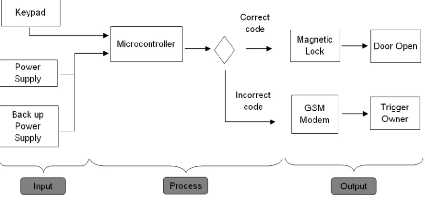
[image:20.612.96.532.266.472.2]The project’s scope focuses more on the designing automatic lock system by using microcontroller. The size of drawer is 14 inches x 19 inches x 8 inches with aluminum type. The microcontroller as a brain system that guide the drawer or locker whereas its will control to open the door automatically with a correct code. Otherwise, its will trigger to owner if drawer had been broken up. Here the mobile communication (GSM) will be implementing to enhance the security system precisely. Figure 1.1 shown the project scope of this project.
4
1.5 Outlines of Progress Report
LITERATURE REVIEW
2.1 Introduction
Analysis of the previous research of the related products will be discussed in a literature review. The purpose of these literature reviews is to expose the knowledge and general idea had been designed by each manufacturer’ company concerned about security system. Hence, the research outcomes idea will be used for improving this project. It’s also explained the software and hardware specifications briefly as references and guidelines to smooth the process of completing the project
2.2 Research about safety and security product
6
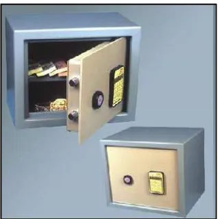
2.2.1 Digimatic Electronic Safety Lockers
[image:23.612.234.393.234.394.2]Apart from standard sizes, the manufacturer design and manufacture digimatic electronic safety lockers according to customers’ specifications & requirements. This safety locker is safe and perfect for storing precious belongings such as cash, jewellery, documents in residences and commercial organizations. Figure 2.1 below show Digimatic Electronic Safety Lockers product.
Figure 2.1: Digimatic Electronic Safety Lockers
Here are some features of this product:
a) Dual password - operations by two persons
b) Password selection through alpha-numeric keys – max 9 characters c) Change of password facility
d) 4th attempt = Alarm facility for 3 minutes followed by auto-freeze for 5 minutes e) Low battery indication - external battery provided
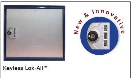
2.2.2 Mini Lok-All Keyless Locker
[image:24.612.194.450.254.408.2]Mini Lok-All allows users to select their own personal code for access. It provides codes resettable system by each user usage. A keyless locker security system is provided with optional shelves. Keyless operation offers self-storage to users and a low maintenance system for operators. Management master keys are provided to easily open and resolve forgotten personal codes. Figure 2.2 below show Mini Lok-All Keyless Locker product.
Figure 2.2: Mini Lok-All Keyless Locker
2.2.3 Aftek SpyGuard