Effects of End Mill Helix Angle on Accuracy for Machining Thin-Rib
Aerospace Component
Raja Izamshah
1,a, Yuhazri M. Y.
2,b, M. Hadzley
1,cM. Amran
1,dand Sivarao Subramonian
1,e1
Department of Manufacturing Process, Faculty of Manufacturing Engineering, Universiti Teknikal Malaysia Melaka, Malaysia
2
Department of Materials Engineering, Faculty of Manufacturing Engineering, Universiti Teknikal Malaysia Melaka, Malaysia
Abstract. Accuracy of machined component is one of the challenging tasks for manufacturer. In the aerospace industry, machining process is widely used for fabrication of unitized-monolithic component that contains a thin-walled structure. During machining, the cutting forces cause deflection to the thin-wall section, leading to dimensional form errors that cause the finished part to be out of specification or failure. Most of the existing research for machining thin-wall component only concentrated on the process planning and the effects of cutter geometric feature is often neglected. Tool geometric feature has a direct influence on the cutting performance and should not be neglected in the machining consideration. This paper reports on the effect of helix angle on the magnitude of wall deflection. The established effects will be used for the development of high performance cutting tool for specifically machining thin-wall component.
Introduction
Machining of aerospace structural components involves several thin-wall rib and flange sections. These thin-wall sections are dictated by design consideration to meet required strength and weight constraints. The unified parts have remarkable merits including high stiffness and lightness. A moving body or airfoil of an aircraft consists of a number of slim ribs to satisfy those requirements. The thickness of these ribs may vary from 100 to 0.1mm.
Kline et al. [1] modelled the milling process of thin-wall rectangular plate element clamped on three edges taking the effects of a flexible endmill. The interaction between the milling forces and the structural deformation were neglected on his study. Therefore, their proposed model can only be applied for the case of relatively rigid workpiece. Sagherian et al. [2] improved Kline’s model by including the dynamic milling forces and the regeneration mechanism. However, they did not consider the effect of workpiece deflection on the cutting geometry, i.e. the radial depth of cut. Later, Tsai and Liao [3] developed an iteration schemes to predict the cutting forces and form error on thin-wall rectangle plate. The cutting force distribution and the system deflections are solved iteratively by modified Newton-Raphson method. They made a few assumptions on the size of the element and their relationship with the transient surface which restricted its applicability. Dynamic model for milling of low rigidity cantilever plate structure was proposed by Altintas et al. [4]. However, the model did not taken into account the changing of structural properties on the material removal process.
Budak and Altintas [5] used the beam theory to analyse the form errors when milling using slender helical endmill for peripheral milling of a cantilever plate structure. The slender helical endmill is divided into a set of equal element to calculate the form errors acting by the cutting forces on both tool and the wall. Later in their work [6], they proposed a feed rate scheduling strategy to reduce the surface errors produced in milling flexible workpiece. However, this approach tends to sacrifice the productivity as reducing the feed rate will increase the machining time.
From the literatures it shows that, there has been little research done on the evaluation of machinability in connection with the remarkable change of chatter characteristics based on the cutter geometrical feature influence such as helix angle. When milling a thin-walled structure, deflection and chatter vibration of the workpiece due to low stiffness had a negative effect on the surface integrity and geometric accuracy [7]. Therefore, it is necessary to select optimal cutter feature when considering those effects. This paper evaluates the machining performance ability based on cutter helix angle that occurs when side milling of cantilever-shaped materials in order to find the optimal cutter geometry.
End mill geometrical feature
The geometrical feature of end mill consists of diameter (D), inscribed circle diameter (DW), number of flute (N), rake angle (γ), clearance angle (η) and helix angle (β) as shown in Fig. 1. Each of the geometric features has their own specific function. Cutting teeth are located on both the end face of the cutter and the periphery of the cutter body. The number of flute can affect the end mill rigidity. Rake angle value will affects the stiffness of the cutting edge and rigidity of the tool. An end mill with a positive rake angle will improve machinability, thereby producing lower cutting force and cutting temperature. Increased helix angle induces increased effective rake angle, thereby improving machinability and accuracy. While a large clearance angle improves surface roughness, but it is easy to be chipped. On the other side, a small clearance angle is likely to produce noise and higher surface roughness.
Fig. 1: End mill geometrical features.
In milling process, helical teeth are generally preferred over straight teeth because the tooth is partially engaged with workpiece as it rotates. Helix angle is the angle formed by a line tangent to the helix and a plane through the axis of the cutter or the cutting edge angle which a helical cutting edge makes with a plane containing the axis of a cylindrical cutter. The helix helps move chips up and out of the cutting zone and also generates an excellent surface finish. Helix angle permits several teeth to cut simultaneously which result in smoother cutting action. Standard end mill helix angle for common machining process are in the ranges between 30° to 45° for sharpness and cutting edge strength. This is adequate for carbon steels, some tool steels or even light finishing passes in aluminum. However, when machining stainless steels, a sharper cutting edge needs to be employed as to lessen the work hardening effects and promote a more free cutting action. This is where a 45° helix angle does well because there will still be some cutting edge strength along with appropriate sharpness needed. This angle is also good for aluminum engaging in a deeper slot or periphery cut.
Experimental design and setup
Using a CNC tool cutter grinder Michael Deckel S20 Turbo, design parameter and proper wheel geometries were determined to produce the end mill. A two flutes carbide flat end mill with a diameter of 10 mm and total length of 70 mm were fabricated to analyze the effects of variable helix angle on part deflection as depicted in Table 1.
Table1: End mill specification
Material Carbide
Diameter 10 mm
Total length 70 mm
Flute length 40 mm
Bottom Flat
No. of flute 2
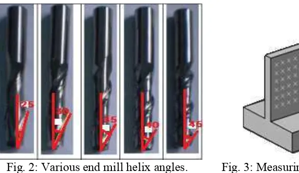
In this experiment, the end mill were design to maintain varying helix angles of 25o, 30o, 35o, 40o and 45o with a constant rake angle of 8o and clearance angle of 6o, respectively as shown in Fig. 2. Others design factors were held constant. Each of the fabricated end mills were then measured using a tool microscope for accuracy.
Fig. 2: Various end mill helix angles. Fig. 3: Measuring points for the workpiece.
Table 2: Workpiece and machining parameters use in the experiment
Workpiece Machining parameter
Type Aluminum alloy 7076 Cutting speed 2400 rpm
Wall thickness 4 mm Axial depth of cut 38 mm
Length 100 mm Radial depth of cut 2 mm
Height with base 50 mm Feed 0.1
mm/tooth
line consists of 19 points with 5mm distance. The wall is to be reduces to 2 mm in thickness with an axial depth of cut of 38 mm. Table 2 shows the workpiece and cutting parameter for the side milling experiment.
(a) (b)
(c) (d)
(e)
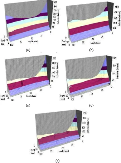
Fig. 4: 3D graph of part deflection for variable helix angles for (a) 25o, (b) 30o, (c) 35o, (d) 40o and (e) 45o.
Experimental Results
flexibility decreases. Due to the decreasing stiffness of the wall as a result of material removal, there is an increasing value of form errors between two regions (start and end) in the feed direction. To a large extent, the more flexible the wall, the higher surface errors result during cutting.
From the graphs, it shows that 40º and 45o helix angle gives the least surface error, followed by 35º and 25º. It shows that end mills with small helix angles tend to cause high cutting forces which deflect the workpiece due to chatter and reduction of the period when the end mill flute engage with the workpiece material.
Conclusion
From the experiment it shows that end mill helix angle affects the magnitude of wall deflection during machining thin-wall components. The magnitude of wall deflection decreases as the value of helix angle increase. End mills with helix angle ranging from 40o to 45o were very effective and would be recommended for the case of milling thin-wall application. The findings from this experiment can be use for the development of high performance cutting tool for specifically machining thin-wall components.
Acknowledgement
The authors gratefully acknowledge Malaysia Ministry of Higher Education for supported the work under the Fundamental Research Grant Scheme No. FRGS/2012/FKP/TK01/03/2 F00134.
References
[1] W.A Kline, R.E. DeVor and I.A. Shareef, The prediction of surface accuracy in end milling, ASME J. Eng. Ind. 104 (1982) 272-278.
[2] R. Sagherian and M.A. Elbestawi, A simulation system for improving machining accuracy in milling, Computers in Industry 14 (1990) 293-305.
[3] J.S Tsai and C.L. Liao, Finite element modeling of static surface errors in the peripheral milling of thin-walled wall, J. of Mat. Processing Tech. 94 (1999) 235-246.
[4] Y. Altintas, D. Montgomery and E. Budak, Dynamic peripheral milling of flexible structures, J. of Eng. for Industry (Transaction of the ASME) 114 (1992) 137-145.
[5] E. Budak and Y. Altintas, Peripheral milling conditions for improved dimensional accuracy, Int. J. of Mach. Tools and Manufacture 34 (1994) 907-918.
[6] E. Budak and Y. Altintas, Modeling and avoidance of static form errors in peripheral milling of plates, Int. J. of Mach. Tools and Manufacture 35 (3) (1995) 459–476.