UNIVERSITI TEKNIKAL MALAYSIA MELAKA
INVESTIGATION ON THE EFFECTS OF RAKE ANGLE
VARIATIONS ON THE END MILL WEAR, CUTTING FORCES
AND SURFACE FINISH
This report submitted in accordance with the requirement of the Universiti Teknikal Malaysia Melaka (UTeM) for the Bachelor Degree of Manufacturing Engineering
(Manufacturing Process) with Honours
by
UNIVERSITI TEKNIKAL MALAYSIA MELAKA
BORANG PENGESAHAN STATUS LAPORAN PSM
TAJUK:
“INVESTIGATION ON THE EFFECTS OF RAKE ANGLE VARIATIONS ON THE ENDMILL WEAR, CUTTING FORCES AND SURFACE FINISH
.
”
SESI PENGAJIAN: 2008/2009 Semester 2
Saya MOHD FAZRIN BIN RAZALI
mengaku membenarkan laporan PSM ini disimpan di Perpustakaan Universiti Teknikal Malaysia Melaka (UTeM) dengan syarat-syarat kegunaan seperti berikut:
1. Laporan PSM / tesis adalah hak milik Universiti Teknikal Malaysia Melaka dan penulis.
2. Perpustakaan Universiti Teknikal Malaysia Melaka dibenarkan membuat salinan untuk tujuan pengajian sahaja dengan izin penulis.
3. Perpustakaan dibenarkan membuat salinan laporan PSM / tesis ini sebagai bahan pertukaran antara institusi pengajian tinggi.
4. *Sila tandakan (√)
SULIT
TERHAD
TIDAK TERHAD
(Mengandungi maklumat yang berdarjah keselamatan atau
kepentingan Malaysia yang termaktub di dalam AKTA RAHSIA RASMI 1972)
(Mengandungi maklumat TERHAD yang telah ditentukan oleh organisasi/badan di mana penyelidikan dijalankan)
FAKULTI KEJURUTERAAN PEMBUATAN
Rujukan Kami (Our Ref) : 29 Julai 2012 Rujukan Tuan (Your Ref):
Pustakawan
Perpustakaan UTeM
Universiti Teknikal Malaysia Melaka Hang Tuah Jaya,
75450 Ayer Keroh, Melaka
Saudara,
PENGKELASAN LAPORAN PSM SEBAGAI SULIT / TERHAD LAPORAN PROJEK SARJANA MUDA MUDA KEJURUTERAAN PEMBUATAN (MANUFACTURING PROCESS): MOHD FAZRIN BIN RAZALI
Sukacita dimaklumkan bahawa laporan PSM yang tersebut di atas bertajuk
“INVESTIGATION ON THE EFFECTS OF RAKE ANGLE VARIATIONS ON THE ENDMILL WEAR, CUTTING FORCES AND SURFACE FINISH” mohon dikelaskan sebagai SULIT/TERHAD untuk tempoh Lima (5) tahun dari tarikh surat ini.
2. Hal ini adalah kerana HASIL KAJIANNYA ADALAH SULIT.
Sekian dimaklumkan. Terima kasih. Karung Berkunci 1200, Ayer Keroh, 75450 Melaka
DECLARATION
I hereby declared this report entitled “Investigation On The Effects Of Rake Angle Variations On The Endmill Wear, Cutting Forces And Surface Finish” is the result of my own research except as cited in the references.
Signature : ………..
Author’s Name : ………..
APPROVAL
This report is submitted to the Faculty of Manufacturing Engineering of UTeM as a partial fulfillment of the requirements for the degree of Bachelor of Manufacturing Engineering (Manufacturing Design) with Honours. The members of the supervisory committee are as follow:
(Signature of Supervisor)
………
APPROVAL
This report is submitted to the Faculty of Manufacturing Engineering of UTeM as a partial fulfillment of the requirements for the degree of Bachelor of Manufacturing Engineering (Manufacturing Design) with Honours. The members of the supervisory committee are as follow:
(Signature of Principle Supervisor)
……….
(Official Stamp of Principle Supervisor)
(Signature of Co-Supervisor)
………
ABSTRACT
ii
ABSTRAK
DEDICATION
I would like to dedicate these special thanks towards my beloved parents and siblings for their endless encouragement, who inspired me throughout my journey of education. I
iv
ACKNOWLEDGEMENT
In the name of Allah,The Most Gracious, Most Graceful.
Alhamdulillah, with full effort and patience in taking all challenges, Projek Sarjana Muda 2 (PSM 2) finally accomplished successfully.
A Special thanks to my supervisor, Prof Dr Mohd Razali b. Muhamad and En Md Nizam b. Abd Rahman for their very valuable editorial advices, comments, guidance and support.
I also would like to thank the entire technician at Fasa B and Advance Machining Centre (AMC) who support and help me to do this study.
Besides, I would like to thank my beloved parents and family for giving endless encouragement, motivation and support throughout my project. Last but not least, I would like to thank my colleagues for their cooperation. Only Allah can repay for what they have done
TABLE OF CONTENT
2.2.3 Multiple-flute end mills 11
2.2.4 Roughing end mills 11
2.3 End mill features 12
2.3.1 Outside diameter 12
vi
2.3.9 Peripheral cutting edge 14
2.3.10 Face cutting edge 14
2.7.1 Description of surface roughness 23
2.8 Cutting tool material 24
2.8.1 Carbide 25
2.8.1.1 Tungsten carbide (WC) 25
2.8.1.2 Titanium carbide (TiC) 26
2.9 Work piece material – mild steel 27
3. METHODOLOGY 29
3.1 Introduction 29
3.3 Summary of project implementation 32
3.3.1 Project mission 33
3.3.2 Literature review 33
3.3.2.1 Journal and articles 33
3.3.2.2 Books 34
3.3.2.3 Internet and web pages 34
3.4 Methodology approaches 35
3.4.1 Selection of work piece material ang cutting tool material 35
3.4.2 Machining parameters 36
3.4.3 Machining 37
4.2.1 Quantitative analysis on Surface Roughness (Ra) 52
4.2.2 Quantitative Analysis on Tool Wear 55
4.2.3 Quantitative Analysis on Cutting Forces 58
5 DISCUSSIONS
5.1 Introduction 61
5.2 Surface quality 61
5.3 Tool wear 62
viii
6 CONCLUSION AND RECOMMENDATIONS 66
6.1 Conclusion 66
6.2 Recommendations For Further Study 67
REFERENCES 68
LIST OF FIGURES
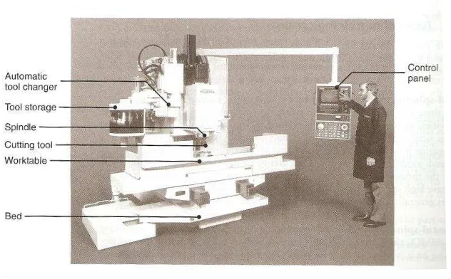
2.1 VCM with parts name 6
2.2 Movement of the VCM machine 6
2.3 Conventional milling 7
2.4 Climb milling 8
2.5 Face mill with indexable inserts 8
2.6 End Milling 9
2.13 Effect of rake angle on machined workpiece surface 17
2.14 Tool wear phenomena 18
2.15 Flank wear 19
2.16 Crater wear 19
2.17 End mill operations 20
2.18 Force acting in the cutting zone during two dimensional cutting 21 2.19 Profile in surface appeared on the workpiece 23
2.20 Microstructure of carbon steel 28
3.1 Process flow chart of the project 30-31
3.2 Mild steel plate 35
3.3 Conventional milling machine 38
3.4 Carbide end mills tool 39
3.5 Dynamometer setup for milling process 40
3.6 Dynamometer experimental set-up for turning 40
3.7 Profilometer Mitutoyo Surftest SJ-301 42
x
3.9 Experiment analysis method 46
4.1 Graph plot between Distance (mm) and Surface Roughness (Ra) - 0⁰ 52 4.2 Graph plot between Distance (mm) and Surface Roughness (Ra) - 5⁰ 53 4.3 Graph plot between Distance (mm) and Surface Roughness (Ra) - 10⁰ 54 4.4 Graph plot between Distance (mm) and Tool Wear (mm) - 0⁰ 55 4.5 Graph plot between Distance (mm) and Tool Wear (mm) -5⁰ 56 4.6 Graph plot between Distance (mm) and Tool Wear (mm) -10⁰ 57 4.7 Data cutting forces for rake angle-0⁰ (N) 58 4.8 Data cutting forces for rake angle-5⁰ (N) 59 4.9 Data cutting forces for rake angle-10⁰ (N) 60
5.1 The finishing workpiece after machining 62
5.2 Endmill cutting tool after machining (0⁰ rake angle) 62 5.3 Endmill cutting tool after machining (5⁰ rake angle) 63 5.4 Endmill cutting tool after machining (10⁰ rake angle) 63
5.5 Endmill cutting tool after machining 64
LIST OF TABLE
2.1 Material properties Tungsten Carbide (WC) 26
2.2 Tensile test data for alloy 28
3.1 Recommended milling parameters 36
3.2 Conventional milling machine 37
3.3 Basic Specifications MITUTOYO Surftest SJ-301 Portable Surface 43 Roughness Tester
3.4 Gantt chart PSM 1 47
3.5 Gantt chart PSM 2 48
4.1 Result data for Surface Roughness (Ra) 50
4.2 Data result for Tool Wear 50
4.3 Data for cutting forces 51
1 considerable amount of these investigations has been directed towards the measurement and prediction of the cutting forces during machining. Knowledge of cutting forces is important because it can effect to the work piece material during machining. (M. Gunay et al., 2006)
Milling cutters are cutting tools used in milling machines or machining centers. This process removes material by their movement within the machine or directly from the cutters shape. Nowadays, milling cutters come in several shapes and many sizes. There is also a choice of coatings, as well as rake angle and number of cutting surfaces. Several types of milling cutters are end mill, slot drill, roughing end mill, ball nose cutter, slab mill, hobbing cutter, face mill and so on that can use in milling cutters. When using milling cutters, we cannot avoid taking consideration on its surface cutting speed, spindle speed, diameter of the tool, feed per tooth, feed rate and also depth of cut. (Kalpakjian and Schmid, 2006)
1.2 Objective of the study
The outcomes of the study will be:
1. To study the effect of end mill rake angle variation to rate of wear of end mill and surface finish of the machined work piece.
2. To understand the impact of end mill rake angle variation to the cutting force during milling process.
1.3 Scope of study
3
1.4 PROBLEM STATEMENT
CHAPTER 2
LITERATURE REVIEW
2.1 Milling
The milling is the most using in cutting process in modern production. The primary objective of the modeling of the cutting forces in milling is to facilitate effective planning of the machining operations to achieve optimum productivity, quality, and cost. The developed analytical methods for cutting force prediction are frequently limited with spectrum of material and machining parameters. The great majority of researches in the area of cutting force use conventional deterministic prediction techniques. Since modern production is influenced by wide range of parameters, it is possible in most cases to obtain by conventional methods only sub-optimal solutions of problems. (M. Kovacic et al. (2004).
Milling machine is capable of performing a variety of cutting operations and is among the most versatile and useful machine tools. The first milling machine was built in 1820 by Eli Whitney (1765-1825). Its basic form is that of a rotating cutter which rotates about the spindle axis (similar to a drill), and a table to which the workpiece is affixed. The workpiece is held securely on the work table of the machine or in a holding device clamped to the table. It is then brought into contact with a revolving cutter. (Stephenson and Agapiou)
5
being replaced with computer controls and machining centers. It can be highly automated in order to increase the productivity, and it is indeed the principle behind transfer lines. (Stephenson and Agapiou)
2.1.1 Machining Center
A machining centers is an advanced, computer controlled machine tools that is capable of performing a variety of machining operations on different surfaces and different orientations of a workpiece without having to remove it from its workholding device or fixture. The workpiece is generally stationary, and the cutting tools rotate as they do in milling, drilling, honing, tapping, and similar operations. Whereas in transfer lines or in typical shops and factories the workpiece is brought to the machine, note that in machining centers, it is the machining operation that is brought to the workpiece. CNC machine allow more operation to be done on a part in one setup instead of moving from machine to machine for various operations. These machines greatly increase productivity because the time formerly used to move a part from machine to machine is eliminated. (Stephenson and Agapiou)
There are three main types of machining centers which is horizontal, the vertical spindle and universal machines. They are available in many types and sizes which may determine by following factors:
The size and weight of the largest piece that can be machined.
The maximum travel of the three primary axes (X, Y, Z).
The maximum speed and feeds available.
The horsepower of the spindle.
The number of tools that the automatic tool changer (ATC) can hold.
tool magazine is on the left of the figure and all operation and movements are directed and modified through the computer control panel. Because the thrust forces in the vertical machining are directed downward, such machines have high stiffness and produces parts with good dimensional accuracy. (Steve and Arthur, 2006)
Figure 2.1: VCM with parts name
The vertical machining center operates on three axes which show in figure2.2:
The X axis controls the table movement left or right.
The Y axis controls the table movement toward or away from the column.
The Z axis controls the vertical movement (up or down) of the spindle or knee.
7 2.1.2 Milling machining operation
There are three basic types of milling operations, which is a) Peripheral milling
b) Face milling c) End milling
2.1.2.1 Peripheral milling
Peripheral milling also called plain milling which the axis of cutter rotation is parallel to the workpiece surface as show in figure. The cutter body which generally is made of high speed steel has a number of teeth along its circumference; each tooth acts like a single-point cutting tool. Cutter of peripheral milling may have straight or helical teeth, resulting in orthogonal or oblique cutting action.
There are two type of peripheral milling:
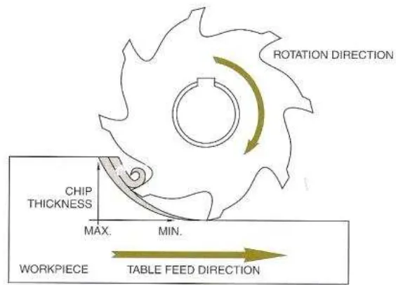
Conventional milling
Climb Milling