THE FRACTURED-BASED MODELING OF PULL-OUT PROBLEM WITH LONG EMBEDDED NYLON 600
Rr. M.I. Retno Susilorini
Department of Civil Engineering, Faculty of Engineering, Soegijapranata Catholic University, Semarang. Jl. Pawiyatan Luhur IV/1, Bendan Dhuwur, Semarang 50234.
E-mail: [email protected]; [email protected]
ABSTRACT
Fracture phenomenon happened during the pull-out process. Previous study of short embedded nylon 600 in cementitious matrix model has proved several new theories with main concern of fracture. Nevertheless, it is necessary to assure that the same theories can be applied accurately and consistently in the pull-out problem with long embedded nylon 600. The research conducts experiment method and analytical method. The experiment method applies pull-out test with long embedded nylon 600 in cementitious matrix and the analytical method is based on previous fractured based pull-out model. The pull-out specimens have embedded length of lf = 110-180 mm. The results of experiment show that all specimens suffer fibers broken. The pull-out process explains several stages: (a) Pre-slip stage, (b) Slip stage, and (c) Strain-hardening stage. The pre-slip loads are found as 400-430 N and pre-slip displacements of no more than 0.1 mm. The slip loads have been observed in the same range of pre-slip loads with displacements of 3-30 mm. The maximum strain-hardening loads are found as 1600-1800N while the broken loads are observed as 1400-1700 N. The maximum displacements are ranged about 100-200 mm. The previous model for pull-out problem with short embedded nylon 600 is applied to the long embedded nylon 600. Clearly, the model has been proven fit to the experimental results. It is emphasized that the theories for the pull-out problem with short embedded nylon 600 are still accurate and consistent applied to long embedded nylon 600. This research meets conclusions: (a) The same theories of pull-out problem with short embedded nylon 600 in cementitious matrix can be applied accurately and consistently for long embedded nylon 600, (b) The unstable and stable fracture process phenomenon exist during the pull-out process, (c) Several stages exist during the pull-out process, (d) The equation of stable crack length of previous model can also be applied for long embedded nylon 600, (e) The equation of load of previous model can also be applied for long embedded nylon 600, (f) The possibility of crack arrester presence is bigger for the long embedded fiber length than the short ones, thus the strain-hardening part in load-displacement curve is longer for the long embedded fiber length.
Keywords: model, fracture, pull-out, long, fiber, nylon
INTRODUCTION
The fiber has been applied in the composites to increase the composite’s performance since ancient period. Fiber existence in composites shows many advantages of crack delaying and resisting (Naaman, et. al, 1990). Hence, fiber takes an important role in determining whole “fiber -reinforced cementitious composite” (FRCC) performance.
The synthetic fiber has advantage in improving the FRCC performance. A good example to describe tensile ductility of FRCC is the using of nylon fiber. Nylon fiber is unique (Nadai, 1950). Nadai explains that nylon fiber will constrict many times and perform two moving surface waves along the fiber length during stretching condition. This phenomenon is called ‘yield point elongation’which has magnitude of 200%-300% of initial fiber length. It should be noted that of the nylon viscosity will
multiple constrictions of nylon fiber appeared by ‘jagged’ phenomenon of stress-strain or load-displacement curves (Nadai, 1950; Avarett, 2004; Susilorini, 2007a). Similar phenomenon is suffered by mild steel and aluminium alloy (Nadai, 1950).
Susilorini (2007a) states that the length of embedded fiber determines the performance of the composite by its fracture behaviour. Hence, the characteristic of long embedded nylon 600 will contribute specific performance in pull-out problem.
According to Susilorini (2007b), fracture based approach becomes a solution to prohibit a catastrophic failure of structure. By using fracture mechanics, the design will achieve more safety margin for structure and higher economic value and also structural benefit. When fracture emerged, crack propagation will be happened and the whole structure is going to failure. Therefore, according to Bazant (1992), the failure of concrete structures should consider the strain-softening phenomenon. The strain-softening phenomenon is related to distributed and localized crack. The crack is growing to larger fracture and bridging stresses at the fracture front. Hence, the suppression of fracture of concrete must be implemented by improving higher toughness and higher tensile ductility (Li and Wang, 2005). Some innovations have been applied to improve toughness and tensile ductility (Fischer and Li, 2004) such as Fiber Reinforced Concrete (FRC) and High Performance Fiber Reinforced Cementitious Composites (HPRFCC) which is known as Engineered Cementitious Composites (ECC). The performance evaluation of those innovations use fracture mechanics.
A comprehensive fractured based model is built to represents the pull-out problem of embedded nylon 600 (Susilorini, 2007a). Some aspects were considered by previous model of short embedded nylon 600. Hence, it is important now to know the result of model which is using long embedded nylon 600.
This research considers several aspects (Susilorini, 2007a): (1) Fracture capacity of embedded fiber is a function of Poisson’s ratio of fiber, (2) Some stages exist during the pull-out and fracture pull-out process, (4) A ‘jagged’ phenomenon exists on strain-hardening part of load-displacement (P-) and stress-strain () pull-out curves, and (4) Unstable and stable fracture process phenomenon exist during the pull-out process.
There is a question, is the previous theories established by short embedded nylon 600 in cementitious matrix still accurate and consistent for model with long embedded nylon 600? This research tries to find whether the theories of pull-out problem with short embedded nylon 600 can be also applied to long embedded nylon 600.
METHODS OF RESEARCH
Figure 1. Dimensions of Pull-Out
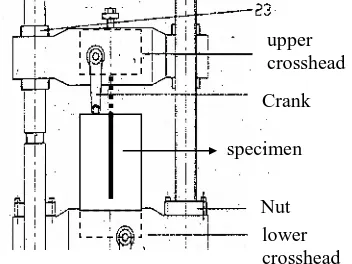
Figure 2. Pull-Out Test Set-Up
The research conducts experiment method and analytical method. The experiment method applies pull-out test with specimens described by Figure 1 while set up of the pull-out test by Figure 2. The pull-out specimens use long embedded nylon 600 fiber in cementitious matrix which is local made (“Golden Fish” brand) with 1.1. mm in diameter. The specimens have embedded length of 110, 150, and 180 mm. Mix design for cementitious matrix is 1:1:0.6 (cement : sand : water). The analytical method is based on previous fractured based pull-out model (with short embedded nylon 600). The model will be evaluated whether it is still accurate and consistent or not.
specimen width = 20
specimen length, l1 = 250 mm
fixed part length, 150 mm
embedded length, lf
70 mm
fiber outer length, 30 mm
fixed part length, 150 mm
specimen
lower crosshead Nut Crank
RESULTS AND DISCUSSION
1. Experiment Result
0 200 400 600 800 1000 1200 1400 1600 1800 2000
0 50 100 150 200
DISPLACEMENT (mm)
L
O
A
D
(N
)
lf=11
lf=15
lf=15
lf=18
Figure 3. Load-displacement relation of specimens with lf = 110– 180 mm
0 200 400 600 800 1000 1200 1400 1600 1800 2000
0 1 2 3
STRAIN
S
T
R
E
S
S
(M
P
a)
lf=11
lf=15
lf=15
lf=18
Figure 4. Stress-strain relation of specimens with lf = 110– 180 mm
The results of experiment show that all specimens suffer fibers broken. The pull-out process includes several stages: (a) Pre-slip stage, (b) Slip stage, and (c) Strain-hardening stage, as seen on Figure 3 and 4. The ‘jagged’ phenomenon exists at strain-hardening section of load-displacement and stress-strain curves (Figure 3 and 4). The pre-slip loads are found as 400-430 N and pre-slip displacements of no more than 0.1 mm. The slip loads have been observed in the same range of pre-slip loads with displacements of 3-30 mm. The maximum strain-hardening loads are found as
1600-2. Modeling
Figure 5. Pull-Out Model at Elastic Stage
A piece of embedded fiber (A’A) with fiber end at A’ is described by Figure 5. Fiber A’A is constrained at A and B but free at C. Free end fiber length named l0and embedded fiber end named lf. A displacement of is applied at C. At this elastic stage, the condition of cementitious matrix and fiber are still composites. The displacement then will caused matrix stress m. The value of matrix stress m then increase until
m
m
m
reached. Hereby, the value of critical matrix stress
m is a bond capacity at the time of crack which represents the ultimate fracture tension capacity. The
m
represents the matrix stress in Poisson’s ratio function.Thus, the strain and stress at BC will be expressed by:
0 1
l
(1)
s 1 1 E
(2)
Figure 6. Pull-Out Model at Unstable Fracture Process
Figure 6 explains that a crack will be performed when displacement keeps growing. This crack causes unstable fracture process. After a crack formed, the stress of composites condition then transferred to fiber. By crack formation, unstable
l0
lf
A’ A
B
C
l2
l0
lf
A’ A B
1 CDETAIL 1
A is removed to left side. When the crack length l2is longer than embedded length lf, then the fiber will be pulled-out.
Figure 7. Pull-Out Model at Stable Fracture Process
After unstable fracture process happened, the stable fracture process will exist. Assume that a crack has formed (Figure 7). The displacement increase and so do the strain 1 and stress 1 at
B’B. One time, strain 1 and stress 1 increasing meets critical value of matrix stress
m and strain. When those critical values are achieved, the displacement increasing is repeated at B’. In thesame time, a new crack of x will be performed at the left side of fiber. It is happened continuously until constraint A is fixed. The constraint A then becomes crack arrester which is preventing crack growth. In this situation, the crack will be stopped to grow and crack length remains l2. Once stable crack length l2 achieved, and then strain at l0 part is transferred to l2part. The stress and strain become:
r
The stable crack length is formulated as:
Figure 8. Load-displacement Relation of Pull-Out Model
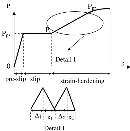
The pull-out modeling results a P- (load-displacement) curve (Figure 8) and formulation (Equation 8) that consists of 3 (three) stages: (a) Stage of pre-slip, (2) Stage of slip, and (3) Stage of strain-hardening.
During the stage of pre-slip, cracks have not been performed yet, and then the fracture process phenomenon doesn’t exist. At the time of critical matrix stress
m exceeded, a lateral crack then performed and the stage of slip and unstable fracture process has just begun. The unstable fracture process keeps going. The crack length increases until stable crack length l2 reached at the end of stage of slip. When the stable crack length l2 is achieved, the unstable fracture process is changed to stable fracture process. The stable fracture process is followed by the stage of strain-hardening and ‘a jagged’ phenomenon exists. In this stage, the increase of the strain will increase the stress until the fiber is is described by Table 1.Table 1. Range value of Es, Eps, and Epr
The analytical calculation has proved that the model fits to experimental results as shown by load-displacement curve (Figure 9). It is also proved that previous model of pull-out problem with short embedded nylon 600 is still accurate and consistent when it is applied to the long embedded nylon 600.
0
Figure 9. The Load-Displacement Relation of Pull-Out Model with lf = 180 mm
3. Discussion
The 3 (three) stages which exist during the pull-out process need to be understood. Recall Figure 3 that describes the stage of pre-slip and stage of slip of load-displacement relation. Review the Detail 1 on Figure 10 and also the Detail 2 on Figure 11 below.
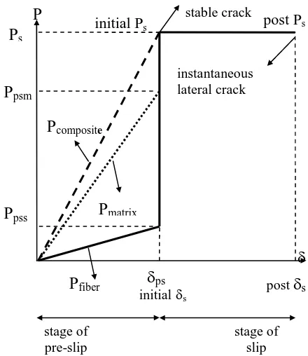
According to Figure 10, the stage of pre-slip of load-displacement curve (Figure 3) is represented by linear curve. The fiber and matrix both in composites condition in this stage. The load P at the end of stage of pre-slip is contributed by P of fiber (Ppss) and also P of matrix (Ppsm), thus PPpss Ppsm. Figure 10 explains that Ppss is smaller than Ppsm when displacement is achieved. After crack performed,
performed instantaneously, so do the unstable fracture process. The initial Ps moves constantly until the post Ps is achieved at the end of stages of slip. The displacement s at the end stages of slip. The part of stage of slip is horizontal-constant (similar to yield curve).
Figure 10. Detail 1 of Figure 3
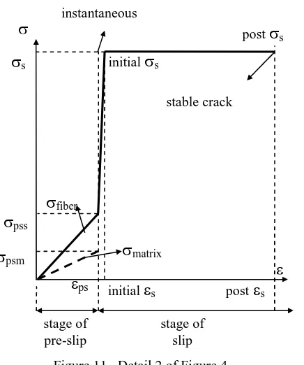
The Figure 11 shows the Detail 2 of stress-strain curve (Figure 4). It should be noted thatpss is higher thanpsm at the timeps is achieved. The fiber and matrix are still in composites condition. After the crack performed, the stress jump to become s. At this time, the starin s is achieved. The stress of initials moves constantly until the stress of posts achieved. It is also found that the part of stage of slip is horizontal-constant (similar to yield curve). When the strain of initial ps is achieved, the crack will perform instantaneously and cause the establishment of stable crack.
The stage is the stage of strain-hardening (Figure 3 and 4) which shows ‘jagged’ phenomenon. This ‘jagged’ form is characteristic of nylon caused by the multiple constrictions during the pull-out process. The multiple constrictions is also generated by fiber yield point elongation (Nadai, 1950).
Figure 11. Detail 2 of Figure 4
It is emphasized by this research that stable crack length (equation 7) of long embedded nylon has distinction compared to the short one. It is shown that all specimens have their nylon fiber broken (lf = 110-180 mm). The reason of this phenomenon is stable crack length is bigger (Susilorini, 2007a) so that the possibility of crack arrester existence is bigger on the long embedded nylon than to the short one. It should be noted that because of the bigger possibility makes the strain-hardening part in load-displacement curve is longer for long embedded fiber length.
CONCLUSIONS
This research meets conclusions, they are:
a. The same theories of pull-out problem with short embedded nylon 600 in cementitious matrix can be applied accurately and consistently for long embedded nylon 600
b. The unstable and stable fracture process phenomenon exist during the pull-out process c. Several stages exist during the pull-out process d. The equation of stable crack length of previous
model can also be applied for long embedded nylon 600
e. The equation of load of previous model can also be applied for long embedded nylon 600
f. The possibility of crack arrester presence is bigger for the long embedded fiber length than the short ones, thus the strain-hardening part in load-displacement curve is longer for the long embedded fiber length
NOTATION
A fiber section area (mm2)
Epr modulus of elasticity at stage of strain-hardening (MPa)
Eps modulus of elasticity at stage of pre-slip (MPa)
Es modulus of elasticity at stage of slip (MPa) P, Pn tension load (N)
a1 total displacement of a stage (mm)
a2 initial length of specimen or fiber that is specific for every stage (mm)
rI ratio of total free-end fiber displacement of free-end at stage of pre-slip
rII ratio of total free-end fiber displacement of free-end at stage of slip
rIII ratio of total free-end fiber displacement of free-end at stage of strain-hardening l0 initial outer fiber length (mm) l2 stable crack length (mm) lf embedded fiber length (mm)
r new fiber in the middle of right side of matrix
1
fiber strain at the middle of right side of matrix (MPa)1 fiber stress at the middle of right side of matrix (MPa)
2
l
fiber stress at l2part when stable crack length achieved (MPa)
ACKNOWLEDGEMENT
The author gratefully acknowledges UBCHEA (United Board of Higher Christian Education) for supporting research grant (2005-2007); and to Prof. Ir. Moh. Sahari Besari, MSc., PhD as Promotor; and also to Prof. Bambang Suryoatmono, PhD. as Co-Promotor; for their great contributions of ideas, discussions, and intensive assistance to the dissertation.
REFERENCES
Avarett, RD (2004). Fracture Mechanics of High
Performance Nylon Fibers, Thesis, Georgia
Institute of Technology, USA.
Bazant, ZP. (1992). “Fracture Mechanics of Concrete: Concepts, Models, and Determination of Material Properties – State of the Art Report”, Proceedings, First International Conference on Facture Mechanics Concrete Structure (Framcos 1), (Ed. Bazant, ZP), Colorado, USA, pp.6-140.
pss
psm
initials
initials posts
ps
fiber
matrix
s
instantaneous
stable crack
posts
stage of pre-slip
Bentur, A., Wu, S.T., Banthia, N., Baggott, R., Hansen, W., Katz, W., Leung, C.K.Y, Li, V.C., Mobasher, B., Naaman, A.E., Robertson, R., Soroushian, P., Stang, H.,
Taerwe, L.R. (1996). “Fiber-Matrix
Interfaces”, High Performance Fiber Reinforced Cement Composites 2, (eds. Naaman, A.E., Reindhardt, H.W.), E&FN Spons, London, 149-191.
Fischer, G., Li, V.C. (2004). “Effect of Fiber Reinforcement on the Response of Structural Members”, Proceedings Framcos-5, (eds. Li,
et. al). Ia-Framcos, 831-838.
Li, V.C., Chan, Y.W. (1994). “Determination of Interfacial Debond Mode for Fiber Reinforced Cementitious Composites”, Journal of Engineering Mechanics, ASCE, Vol. 120, No.
4, April, 707-719.
Li, V.C., Stang, H. (1997). “Interface Property Characterization and Strengthening Mechanism in Fiber Reinforced Cement Based Composites”, (Review Arcticle), Journal of Advanced Cement Based Materials, Vol. 6, pp. 1-20.
Li, V.C., and Wang, S. (2005). “Suppression of Fracture Failure of Structures by Composite Design based on Fracture Mechanics”, corresponding paper in Compendium of Papers CD ROM, Paper 5543.
Morisson, J.K., Shah, S.P., Jenq, Y.S. (1988). “Analysis of Fiber Debonding and Pull-out in Composites”, Journal of Engineering Mechanics, ASCE, Vol. 114, No. 2, February, pp. 277-294.
Naaman, AE., Namur, GG., Alwan, JM., Najm, HS. (1990). “Fiber Pullout and Bond Slip. I: Analytical Study”, Journal of Structural Engineering, ASCE, vol. 117, No. 9, pp. 2769-2790.
Nadai, A. (1950). Theory of Flow and Fracture of
Solids, Volume I, McGraw-Hill Company. Inc,
New York, USA.
Sumitro, S., Tsubaki, T. (1998). “Microfractural Pullout Model of Steel Fiber Reinforced Concrete”, Proceedings Framcos-3, AEDIFICATIO Publishers, Freiburg, Germany, pp. 451-465.
Sun, W., Lin, F. (2001). “Computer Modelling and FEA Simulation for Composite Single Fiber Pullout”, Journal of Thermoplastic Composite Materials, Vol. 14, No. 4, pp. 327-343.
Susilorini, Retno, M.I. (2007a). “Model Masalah
Bandung.
Susilorini, Retno, Rr. M.I. (2007b). “Fractured Based Approach for Structural Element Design– Safe Building, Safe City”, Proceeding Third International Conference on Economic and Urban Management “City Marketing, Heritage, and Identity), PMLP Unika Soegijapranata, Semarang, pp.451-465.
Susilorini, Retno, Rr. M.I. (2008). “Fracture to Failure: a Fracture Mechanics Approach for Bridge Failure Analysis”, Proceeding International Seminar “Rekayasa Perencanaan XI”, UPN Jawa Timur, Surabaya, pp. M.20.1 -M.20.6.
Wang, Y., Li, V.C., Backer, S. (1988a). “Analysis of Synthetic Fiber Pull-out from a Cement Matrix”, (eds. Mindess, S., Shah, S.P), Proceedings of Material Research Society Symposium, Vol. 114, Pittsburgh, pp. 159-165. Wang, Y., Li, V.C., Backer,S. (1988b). “Modeling