UNIVERSITI TEKNIKAL MALAYSIA MELAKA
DESIGN ENHANCEMENT AND ANALYSIS OF LUBE OIL
FILTRATION PROCESS FOR ENGINE LUBRICATION
APPLICATION
This report submitted in accordance with requirement of the Universiti Teknikal Malaysia Melaka (UTeM) for the Bachelor’s Degree in Mechanical Engineering
Technology (Maintenance Technology) with Honours
by
SOLEHUDDIN BIN SOFI B071210023
930627-01-5187
UNIVERSITI TEKNIKAL MALAYSIA MELAKA
BORANG PENGESAHAN STATUS LAPORAN PROJEK SARJANA MUDA
TAJUK: Design Enhancement and Analysis of Lube Oil Filtration Process for
Engine Lubrication Application
SESI PENGAJIAN: 2015/16 Semester 2
Saya SOLEHUDDIN BIN SOFI
mengaku membenarkan Laporan PSM ini disimpan di Perpustakaan Universiti Teknikal Malaysia Melaka (UTeM) dengan syarat-syarat kegunaan seperti berikut:
1. Laporan PSM adalah hak milik Universiti Teknikal Malaysia Melaka dan penulis. 2. Perpustakaan Universiti Teknikal Malaysia Melaka dibenarkan membuat salinan
untuk tujuan pengajian sahaja dengan izin penulis.
3. Perpustakaan dibenarkan membuat salinan laporan PSM ini sebagai bahan pertukaran antara institusi pengajian tinggi. atau kepentingan Malaysia sebagaimana yang termaktub dalam AKTA RAHSIA RASMI 1972)
(Mengandungi maklumat TERHAD yang telah ditentukan oleh organisasi/badan di mana penyelidikan dijalankan)
( )
iii
DECLARATION
I hereby, declared this report entitled “Design Enhancement and Analysis of Lube Oil Filtration Process For Engine Lubrication Application” is the results of my own
research except as cited in references.
Signature :………
Name : SOLEHUDDIN BIN SOFI
iv
APPROVAL
This report is submitted to the Faculty of Engineering Technology of UTeM as a partial fulfillment of the requirements for the degree of Bachelor of Engineering Technology (Mechanical Engineering Technology) (Hons.). The member of the supervisory is as follow:
v
ABSTRACT
vi
ABSTRAK
vii
DEDICATIONS
I acknowledge my sincere indebtedness and gratitude to my parents and my family for their love, support and sacrifice throughout my whole life. Their sacrifice had inspired me from the day I born until what I have become today. From the day I have
born, they have teach me about how to learn and write. Without them, I cannot achieve the success. I cannot find an appropriate words that could properly describe my appreciation for their devotion, support and faith in my ability to achieve what I
have today. Lastly, I would like to thanks all person which contributes to my bachelor degree project directly or indirectly. I would like to acknowledge their comments and suggestions, which has crucial for the successful completion of this
viii
ACKNOWLEDGMENTS
ix
LIST OF ABBREVIATIONS, SYMBOLS AND NOMENCLATURES...xiv
CHAPTER 1: INTRODUCTION………..1
2.4 Properties of Lubricant Oil………...13
x
xi
CHAPTER 4: RESULT & DISCUSSION………..46
4.1 Introduction………...46
4.2 Product Design Specification………...47
4.2.1 Product Design Specification For Filtration Process………...47
4.2.2 Quality Function Deployment………..49
4.3 Design Failure Mode Analysis………....50
4.4 Morphology Chart………...51
4.5 Conceptual Design………...54
4.6 Concept Design………...55
4.6.1 Concept Design 1………...55
4.6.2 Concept Design 2………...56
4.6.3 Concept Design 3………...57
4.6.4 CAD Drawing Concepts………..58
4.7 Conceptual Evaluation………....58
4.7.1 Concept Screening………...59
4.8 Material Selection………...60
4.9 Oil Analysis Test………....64
4.9.1 Viscosity Test Result………...64
4.9.2 Number of Element Test Result………..67
4.9.3 Flash Point Test Result………...70
CHAPTER 5: CONCLUSION & RECOMMENDATION………...72
5.1 Conclusion……….72
5.2 Recommendation………...73
REFERENCES………..74
xii
LIST OF TABLES
2.1 The Oil Comparison Chart………...8
2.2 The Basic Functions of a Lubricant………...10
2.3 The Differences between Chemical and Electrochemical Corrosion………...12
2.4 The Typical Source of Element Analysed by Spectroscopy in Oil………...16
2.5 The Comparison Study of Used Lube Oil Based on The Previous Research…...19
2.6 The Beta Rating and Efficiency of Filter……….25
2.7 Type of Filtration……….26
4.1 Product Design Specification for The Used Lube Oil Filtration Process………....47
4.2 Design Failure Mode Analysis………....50
4.3 Morphology Chart for Filter………....51
4.4 Morphology Chart for Fitting………...52
4.5 Morphology Chart for Pump………...52
4.6 Morphology Chart for Piping and Valve………...53
4.7 The Discrete Activities Under Conceptual Design………...54
4.8 Parts with Options………...55
4.9 Parts with Options………...56
4.10 Parts with Options………...58
4.11 Concept Screening Using The Screening Matrix………....59
4.12 Material Selection of Piping………....60
4.13 Material Selection for Tank……….61
4.14 Material Selection for Magnet……….62
4.15 Material Selection for Filter Media……….62
4.16 Type of Supported Filter Media………..63
4.17 Material Selection for Valve………...63
4.18 Material Selection for Fitting………..64
4.19 The Result of Kinematic Viscosity……….65
4.20 The Result of Kinematic Viscosity……….65
4.21 The Result of Number of Element………..67
4.22 The Result of Number of Element………..68
xiii
LIST OF FIGURES
2.1 The Mechanism of Solid Lubricant………7
2.2 The Comparison between Surface Filtration and Depth Filtration…………...25
2.3 Schematic Diagrams of The Common Design of Based Filter……….27
2.4 The Pattern of Flux Distribution and The Collected Dirt of Magnetic Filter...28
2.5 The Design of the Coalescing Systems Unit………28
2.6 The Centrifugal System of Oil Filter………29
2.7 The Combination Compact Vacuum With The Media Based Filtration……..30
2.8 The Illustration of Pleated Microfiber Glass………31
2.9 The Activated Carbon Filter……….32
2.10 The Differences Between Cellulose Filter and Nano Filter………..33
2.11 The Types of Design……….34
2.12 The Interface of SolidWorks Software……….35
2.13 The Benefits of Oil Analysis………36
2.14 RDE-AES Sample Stand Showing Oil Sample Being “Burned”……….38
2.15 Heated Viscometer………39
3.1 The Methodology Flow Chart for PSM………42
4.1 Concept Design 1………..55
4.2 Concept Design 2………..56
4.3 Concept Design 3 (Front View)………57
4.4 Concept Design 3 (Back View)……….57
4.5 The Percentage Change of Kinematic Viscosity………...66
4.6 The Change of Number of Element………...70
xiv
Ca2 – BaF2 - Calcium Fluoride-Barium Fluoride Eutectic
Cr - Chromium
xv Sb - Antimony
Si - Silicon
Sn - Tin
Ti - Titanium
USA - United States of America
UTeM - Universiti Teknikal Malaysia Melaka QFD - Quality Function Deployment
V - Vanadium
1 1.1 Background
Lubricant is an element that has been used to smooth the movement between two contact surfaces. Lubricant could be made from solid, semi-solid or liquid elements. The variation of elements in the lubricant makes it become multipurpose. In other words, it can be applied in any circumstances based on its properties.
The smoothness of the movement between two contact surfaces is due to the reduction of friction. Friction occurs when there are contact between two moving surfaces. Consequently, there is resistance force that occurs between the movements of the contact surface (Sahoo, 2009). The reduction of friction will ensure that there are no disturbance occur in the movement of the contact surface.
Lubricant’s primary functions are to help overcome the friction (Bannister, 2007). Besides that, lubricant also can minimize corrosion by providing a lubricating film that acted as a barrier to prevent the surface from moisture in the air and others corrosive substances. Then, it also plays an important role to seal out contaminates by flush out contaminants away from the systems. Lastly, lubricant can reduce the energy usage.
The main function of the engine lubrication system is to maintain the efficiency operation of the engine system and maintain a positive and continuous oil supply to the bearing. In addition, the pressure of the engine oil should be high enough to cause the oil flow that is required for proper cooling. (Halderman &
INTRODUCTION
2
Mitchell, 2005). So, it is important to keep and maintain the lubrication system of the engine.
Besides that, lube oil can prolong the lifespan of the moving parts that operate in engine system by different condition in terms of speed, temperature and pressure. At the early stage of the lube oil usage, there were no standardized usage and limitation of time or mileage that were used to maintain the effectiveness of the lube oil to lubricate all the components in the engine system. Due to that reason, lube oil need to be changed more frequently (Ahmed & Nassar, 2011).
During engine operation, there will be a contamination occurs and this will make the engine component damage. Wear debris, peroxides, acids, soot particles, or sludge may be the sources of the contaminants (Ahmed & Nassar, 2011). So, when the lube oil no longer can be used for protecting the component in the engine system and it becomes hazardous. It needs to be changed.
Once the lubricant is being replaced, the lubricant need to be disposed in a proper ways. It is a major management challenge in terms of the method of controlling the disposal of the used lube oil. If not disposed properly, it can dangerous the ecosystem and environment. It can lead to the health problem. Many countries in the world admitted that the problem of the environmental problem is caused by the waste or used lubricating oil (Cooke, 1982). For example, about 2 billion gallons of oils are produced each year in the USA (Coyler, 2000).
This shows that, without a proper planning and management in handling the lubricating oil. It will make a disaster to the earth. So, one of the ways in order to keep the used lube oil from being dumped is to recycle it. The initiative is to design a new filter that can filtrate all the contaminant from the used lube oil. Due to the lube oil filter, all the contaminant in the lube oil and all cost in order to maintain the component in the engine system can be reduce.
3
make the used lube oil have a higher resistance to flow. In other words, depth filter has a higher possibility to clean out more contaminants from the used lube oil.
In addition, each of the filters has its own filtration ratio. It is also known as Beta Rating. Based on the rating, the efficiency of the filter can be easily determined. The higher the Beta Rating, the higher the efficiency of the filter. When the efficiency of the filter higher, more contaminants will be trapped in the filter. Due to that, the quality of the used lube oil that undergo a filtration process will be improved.
In order to ensure that the filtration process of used lube oil can be done smoothly, several types of the filtration process that have been studied and it have been chosen to improve the quality of the filtration process. There are five types of filtration process which is media based filtration, magnets, coalescing systems, centrifugal systems and vacuum dehydration.
Besides that, the filtration media also need to be studied because it is important to choose the suitable material for the filter. If the material used for the filter is not suitable for the filtration process, the filter will become ineffective and useless. Then, the contaminants also will not be trapped. So, there are three types of filtration media that have been used in this redesign process of filter which is pleated microfiber glass, polypropylene and activated carbon.
In fact, the filter already have been made by someone else before this. But in order to get the best result in terms of the properties of the used lube oil and to increase the quality of the recycle used lube oil, the new filter will be designed. For the engineering design process, the redesign process is chosen in order to create an improvement to the current design of the filter. SolidWorks is one of the components in Computer Aided Design (CAD) is used in order to redesign the filter.
4 1.2 Problem Statement
The used lube oil that has been produced can be considered as a source or as a resource of environmental pollution (Emam & Shoaib, 2012). Environmental pollution can be defined as the physical and biological composition that was affected and contaminated, resulting in a change in the natural ecosystem and adversely the environmental processes (Gray, 2012).
Usually, the used oil will be dumped to the toxic waste disposal sites for disposal process. This is because used oil is one of the material wastes. Used oil needs to be managed properly and carefully because if it is wrongly handled, it can become severe to the environment. There are possibilities that the increment usage of the used oil will make the solid waste disposal sites are no longer able to accommodate all the material wastes. This scenario will lead to the environmental pollution. In order to avoid the disposal of the material wastes from becoming uncontrollable, the used oil needs to be recycled.
Besides that, there are high demand for the oil in the industries and this will affect the oil reserve. In other words, the decrement of the oil sources will occurs. Due to that, it will contribute to the increasing of the petroleum price each year. The impact of this scenario, an initiative such as filtration process of the used oil must be done to approach a way to make oil as a renewable sources. This initiative will be a solution to save the environment and to avoid the depletion of oil.
In addition, the production of new oil needs a lot of cost. The reuse of the used oil can reduce the cost of the production to make a new oil. It also can save crude oil supply. Due to that, the recycle of the used oil can make the used oil become reusable. When the used oil become a renewable sources, there is no more cost needed in order to produce a new oil.
5
the properties of the used lube oil. So, the filtration aids should be redesign to improve the properties of the used oil
1.3 Objectives
From the problem statement that have been stated, the purpose of this research is: i To determine the regeneration process of used lube oil.
ii To determine which types of filter is more suitable and proper for the used lube oil filtration process.
iii To improve the design of the used lube oil filtration process.
iv To analyse the properties of the used lube oil after the improvement of the filtration process.
1.4 Scopes
In order to achieve the objectives of the study, several scopes have been identified: i Determining the regeneration process of used lube oil based on the previous
research.
ii Determining which types of filter is more suitable and proper for the used lube oil filtration process.
iii Improving the design of the used lube oil filtration process using SolidWorks software.
6 2.1 Lubricant
Lubricant is used on many equipment and machinery to ensure that no failure occurs in the equipment and machinery during the run time. It provides a film coating on the surface of material to avoid the degradation of the surface and reduce the surface roughness of the material (Khonsari & Booser, 2001). Film coating will avoid the surface of material from the resistance when moving over another surface. Thus, this will smoothen the movement between the surfaces. Besides that, it also reduces friction, wear and heat production.
In the engine system, lubricant plays an important role to seal out contamination. Without lubricant, the component of the engine will not run efficiently. Thus, the combustion process will not be performed smoothly. In addition, the disturbance efficiency of the engine due to the friction by sliding between the components of the engine system. This will lead the engine system to overheat and causes wear to the engine components (Pirro & Wessol, 2001). So, lubricant is important to prolong the life of a component in the engine system. Therefore, lubricant is needed to overcome this problem with proper monitoring and maintenance.
LITERATURE REVIEW
7 2.2 Type of Lubricant
There are many variations of the lubricant depends on its function and purpose. Each type of lubricant is specialized only for a certain circumstance. If lubricant is not applied in the right circumstances, the lubricant will not bring any benefits. Furthermore, it only causes the component of the equipment will be overheat and seizing.
2.2.1 Solid Lubricant
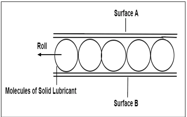
Solid lubricants provide thin films of a solid between two moving surfaces to reduce friction, wear and to facilitate the movement of two contacting surfaces. The mechanism occurs when there are two contact surfaces of material slide over between each other and molecule of solid lubricant will roll, this will facilitate the movement of the surface. When there is too much of solid lubricant applied between two contact surfaces, each molecule of solid lubricant will roll and it will increase the friction between molecules. It will contribute to increasing the rate of wear. Figure 2.1 below shows the mechanism of solid lubricant.
8
Solid lubricants usually used for high temperature, aerospace, vacuum, nuclear radiation, and other circumstances that not tolerated by liquid and semi-solid lubricants. In addition, the common type of solid lubricants are Molybdenum disulphide (MoS2), Graphite and Calcium fluoride-barium fluoride eutectic (Ca2 – BaF2)(Khonsari & Booser, 2001).
2.2.2 Liquid Lubricant
It is in a liquid form. It provides a film of liquid between two moving surfaces according to the viscosity. If viscosity is thin, it will produce thin films on any lubricate surface. So, when two contacting surfaces are moving, the surfaces still collide and contact each other. This type of lubricant usually applied to the heavy machinery. While, when the viscosity are thick, it will produce thick films between the surfaces. Thicker films of lubricants give a total separation between two contacting surfaces. It is usually applied to the speedy machinery.
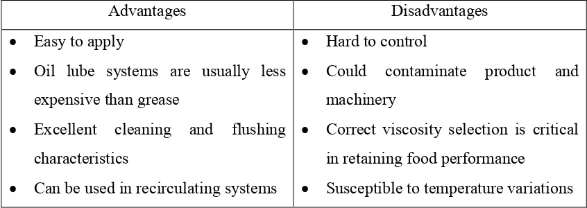
Liquid lubricant is a common type of lubricant that used in the engine system. This is due to the properties of liquid lubricant that can smoothen the movement of the component in the engine system and can make the engine system well function. Lube oil is one of the examples of the liquid lubricant. Table 2.1 shows advantages and disadvantages of the lube oil.
Table 2.1: The Oil Comparison Chart (Bannister, 2007)
Advantages Disadvantages
Easy to apply
Oil lube systems are usually less expensive than grease
Excellent cleaning and flushing characteristics
Can be used in recirculating systems
Hard to control
Could contaminate product and machinery
Correct viscosity selection is critical in retaining food performance
9 Within systems, generally more
stable as a lubricant than grease With correct application, no limit to
machine speed
Susceptible to leakage
2.2.3 Semi-solid Lubricant
Semi-solid lubricant is lubricating oil thickened with a gelling agent such as non-melting powder or metallic soap. In addition, semi-solid lubricant are given first consideration for lubricating ball and roller bearings in electric motors, aircraft accessories, household appliances, machine tools, automotive wheel bearings, instruments, railroad, and construction equipment. It also commonly used for low-speed sliding application and small gear units (Khonsari & Booser, 2001). Grease is a common example of semi-solid lubricant.
There are 9 reasons grease are chosen as a lubricant:
i Provide adequate lubrication to reduce friction and to prevent harmful wear of components.
ii Protect against rust and corrosion.
iii Act as a seal to prevent entry of dirt and water.
iv Resist leakage, dripping, or undesirable throw-off from the lubricated surfaces.
v Retain apparent viscosity or relationship between viscosity, shear, and temperature over useful life of the grease in a mechanical component that subjects the grease to shear forces.
vi Not stiffen excessively to cause undue resistance to motion in cold environments.
vii Have suitable physical characteristics for the method of application.
viiiBe compatible with elastomer seals and other materials of construction in the lubricated portion of the mechanism.