UNIVERSITI TEKNIKAL MALAYSIA MELAKA
MEASUREMENT OF MAGNETIC FIELD GENERATED BY
LIGHTNING FOR DETERMINATION OF LIGHTNING STRIKE
DIRECTION
This report submitted in accordance with the requirement of Universiti Teknikal Malaysia Melaka (UTeM) for the Bachelor of Electrical Engineering Technology
(Industrial Power) with Honours
by
NUR DAYANA FATIN BT ZULKHURNAIN B071210161
931214-10-5170
UNIVERSITI TEKNIKAL MALAYSIA MELAKA
BORANG PENGESAHAN STATUS LAPORAN PROJEK SARJANA MUDA
TAJUK: Measurement of magnetic field generated by lightning for
determination of lightning strike direction
SESI PENGAJIAN: 2015/16 Semester 2
Saya NUR DAYANA FATIN BT ZULKHURNAIN
mengaku membenarkan Laporan PSM ini disimpan di Perpustakaan Universiti Teknikal Malaysia Melaka (UTeM) dengan syarat-syarat kegunaan seperti berikut:
1. Laporan PSM adalah hak milik Universiti Teknikal Malaysia Melaka dan penulis. 2. Perpustakaan Universiti Teknikal Malaysia Melaka dibenarkan membuat salinan
untuk tujuan pengajian sahaja dengan izin penulis.
3. Perpustakaan dibenarkan membuat salinan laporan PSM ini sebagai bahan pertukaran antara institusi pengajian tinggi.
4. **Sila tandakan ( )
SULIT
TERHAD
TIDAK TERHAD
(Mengandungi maklumat yang berdarjah keselamatan atau kepentingan Malaysia sebagaimana yang termaktub dalam AKTA RAHSIA RASMI 1972)
(Mengandungi maklumat TERHAD yang telah ditentukan oleh organisasi/badan di mana penyelidikan dijalankan)
(TANDATANGAN PENULIS)
Alamat Tetap:
No. 27 Taman Sungai Jagung
08000, Sungai Petani
Kedah Darul Aman
Disahkan oleh:
(TANDATANGAN PENYELIA)
Cop Rasmi:
DECLARATION
I hereby, declared this report entitled “Measurement of magnetic field generated by lightning for determination lightning strike direction” is the results of my own
research except as cited in references.
Signature :………
Name : NUR DAYANA FATIN BT ZULKHURNAIN
v
APPROVAL
This report is submitted to the Faculty of Engineering Technology of UTeM as a partial fulfillment with the requirements for the Bachelor of Electrical Engineering Technology (Industrial Power) with Honours. The member of the supervisory is as follow:
vi
ABSTRACT
This project was to develop a lightning detection system where it will be focused on measurement of magnetic field generated by lightning for determination of lightning strike direction. There are lots of detection system to determine the lightning strike such as the Lightning Positioning and Tracking System (LPATS) and Lightning Location and Protection (LLP). Magnetic direction finding is one of them. The measurement of the magnetic field produced by lightning detected using an antenna that act as a sensor. The loop antenna is developed by using PVC and coaxial cable with 50 ohm impedance is placed inside. Furthermore, the antenna is measured on the North and South component only. Output of the antenna is connected to the active integrator circuit by using AD8067 for the purpose of integrates the voltage output from the loop. PCB design of the circuit is used OrCAD software. From the circuit the measurement of the dB/dt observed the waveform on the Teledyne LeCroy HDO4024 digital storage oscilloscope (DSO). The lightning strike activity is monitored time by time. Throughout this project, the several parameter from magnetic field of the output loop antenna can determine the direction of lightning strike with some mathematic calculations and equations. The distance had been determined from the range of 0.5 km to 40 km and the lightning strike direction is defined on the East due to the cloud propagation. In conclusion, the objectives are successfully achieved and further research need to be done to increase the result accuracy of this project.
keyword: Lightning Strike Direction, Measurement of magnetic Field, Loop
vii
ABSTRAK
Projek ini adalah untuk membina sistem pengesanan kilat berdasarkan ukuran medan magnetik yang dihasilkan oleh kilat untuk mengkaji arah panahan kilat itu berlaku. Terdapat banyak sistem pengesanan menentukan panahan petir seperti Lightning Positioning and Tracking System (LPATS ) and Lightning Location and Protection (LLP). Penemuan arah magnetik ialah salah satu teknik sistem pengesanan yang lain. Ukuran medan magnetik dihasilkan oleh kilat dikesan dengan menggunakan antenna sebagai sensor. Antena gelung dibangunkan dengan menggunakan PVC dan kabel sepaksi 50 ohm yang diletakkan di dalamnya. Selain itu, gegelung antenna dibangunkan mengikut arah Utara dan Selatan sahaja. Output antena akan disambungkan kepada litar pengamiran aktif menggunakan AD8067 dengan tujuan untuk mengintegrasikan output voltan dari antena gelung tersebut. Reka bentuk litar PCB akan menggunakan perisian OrCAD. Dari litar pengamiran aktif tersebut ukuran dB/dt akan diperhatikan dalam bentuk gelombang di osiloskop storan digit (DSO) Teledyne LeCroy HDO4024. Kegiatan panahan petir akan dipantau dari masa ke masa. Keseluruhan projek ini, pengesanan voltan medan magnetik daripada output antenna gelung dapat menentukan arah panahan petir dengan menggunakan sedikit pengiraan matematikal. Panahan kilat dapat dikesan dalam lingkungan 0.5 km hingga 40 km dan arah yang dikenalapasti adalah daripada arah Timur berdasarkan pergerakan awan. Kesimpulannya, keseluruhan objektif berjaya dicapai tetapi penambahbaikan perlu dilakukan untuk meningkatkan tahap ketepatan data yang akan diperolehi pada masa hadapan.
Kata Kunci : Arah panahan Kilat, Ukuran Medan Elektromagnet, Antena
viii
DEDICATIONS
ix
ACKNOWLEDGMENTS
I would like to express my gratitude and appreciation to all those who gave me the possibility to complete this report. I express my deep sense of gratitude to my helpful supervisor , Dr Zikri Abadi bin Baharudin for his guidance and inspiration regarding the project of "Measurement of Magnetic Field Generated by Lightning for Determination of Lightning Strike Direction" for completing project smoothly.
My deepest gratitude also extends to Mr. Asri bin Din, my co-supervisor for his kind guidance and encouragement throughout this project development.
I would like to thank my parents and family for giving me full support, understanding and patience. Without their support, I would not have been able to finish my research project.
x
LIST OF SYMBOLS AND ABBREVIATIONS ... xvi
CHAPTER 1 ... 1
1.5 Significant of The Project ... 4
1.6 Organization ... 4
CHAPTER 2 ... 5
2.0 Introduction ... 5
xi
2.2.1 Preliminary Breakdown ... 6
2.2.2 Stepped Leader ... 7
2.3 Type of Lightning ... 8
2.3.1 Cloud-to-Ground ... 8
2.3.2 Intracloud Lightning... 9
2.3.3 Cloud-to-Cloud ... 10
2.4 Technique of Lightning Strike Location ... 10
2.4.1 Magnetic Field generated by Lightning ... 10
2.4.2 Type of antenna used to Measure Magnetic Field ... 12
2.5 Determination of Lightning Strike Direction ... 14
2.5.1 Azimuth Coordination to the Lightning Strike Direction ... 15
2.5.2 Azimuth Angle to the lightning strike direction ... 15
2.6 Determine of Lightning Strike Distance ... 16
2.7 Summary of Literature Review ... 17
CHAPTER 3 ... 18
3.0 Introduction ... 18
3.1 Flow Chart Method ... 18
3.2 Circuit Modelling and Hardware ... 25
3.2.1 Circuit Developing using OrCAD ... 25
3.2.2 PCB Design ... 27
3.2.3 Device Requirement ... 29
xii
3.3 Data Measurement ... 36
3.4 Data Analysis and Result Calculation ... 37
CHAPTER 4 ... 39
4.0 Introduction ... 39
4.1 Simulation Circuit Result ... 39
4.2 Measured Waveform ... 41
4.2.1 Data Determination on Measured Waveform ... 43
4.2.2 Tabulated Data of Magnetic Field Waveform ... 45
4.2.3 Graph Relationship Based on Magnetic Field Table Data ... 46
4.3 Analysis Waveform ... 47
4.3.1 Profile Cloud-To-Ground Waveform For different Distance ... 48
4.4 Direction of Lightning Strike from Magnetic Field Waveform ... 50
CHAPTER 5 ... 52
5.0 Introduction ... 52
5.1 Summary of Project ... 52
5.2 Achievement of Project Objectives ... 53
5.3 Problems Faced During Project Development ... 53
5.4 Suggestion for Future Work ... 54
APPENDIX A ... 56
xiii
LIST OF FIGURES
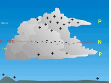
Figure 2.1: Thundercloud charges, P- positive charge uppermost region, N-negative
charge and p-positive charge bottom region. ... 6
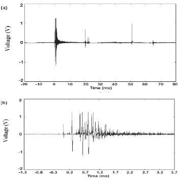
Figure 2.2: Preliminary Breakdown Pulse ... 7
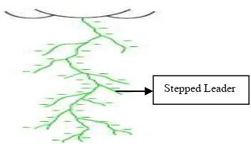
Figure 2.3: Stepped Leader Diagram ... 8
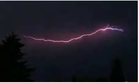
Figure 2.4: Cloud-to-ground. ... 9
Figure 2.5 : Intracloud ... 9
Figure 2.6 : Cloud-to-Cloud ... 10
Figure 2.7 : MF Waveform Propagation ... 11
Figure 2.8: Crossed-loop antenna. ... 13
Figure 2.9: Single-loop antenna. ... 13
Figure 2.10: Determination of the Angle to the Lightning Strike Point. ... 15
Figure 3.1: Overall Project Flowchart ... 19
Figure 3.2 : EM Detection System Project Flowchart ... 21
Figure 3.3: Waveform Analysis Project Flowchart ... 23
Figure 3.4: Basic Active Integrator Circuit ... 25
Figure 3.5: Active Integrator Simulation Circuit ... 26
Figure 3.6: Frequency of the band operation signal of circuit ... 27
Figure 3.7: Schematic for PCB layout. ... 28
Figure 3.8: PCB design ... 28
Figure 3.9: Integrated Circuit (AD8067 ARTZ-REEL 7) ... 29
Figure 3.10: Top view of AD8067 connection diagram ... 30
Figure 3.11: The complete circuit for magnetic field measurement. ... 31
Figure 3.12: Diagram (A) and equivalent circuit (B) of a single-ended output coaxial loop antenna with both ends of the cable terminated in 50 [1]. ... 32
Figure 3.13: Construction of coaxial cable gap for the loop antenna ... 33
Figure 3.14: Coaxial Cable Structure ... 33
Figure 3.15: BNC Connector ... 34
Figure 3.16: Magnetic Field Antenna ... 35
Figure 3.17: Electric Field Antenna ... 35
Figure 3.18: The Teledyne LecroyHDO4024 Oscilloscope ... 36
Figure 3.19: Specification of Teledyne LecroyHDO4024 Oscilloscope ... 37
Figure 4.1: Simulation Circuit Result ... 40
Figure 4.2: Oscilloscope calibration ... 41
Figure 4.3: Waveform Capture on the Oscilloscope ... 42
Figure 4.4 : Electric Field Waveform Displayed in WaveStudio ... 43
xiv
Figure 4.6: Graph lightning strike distance (km) against Time in Delay Between EF
and Magnetic Field ... 47
Figure 4.7 : Measured Waveform 6.48 km ... 48
Figure 4.8 : Measured Waveform for 6.14 km ... 48
Figure 4.9: Measured Waveform for 22.14 km... 49
Figure 4.10: Measured Waveform for 22.43 km... 50
xv
LIST OF TABLE
xvi
LIST OF SYMBOLS AND ABBREVIATIONS
AC = Alternating Current
BDP = Bachelor Degree Project
BNC = Bayonet Neill-Concelman
CG = Cloud-to-Ground
CC = Cloud-to-Cloud
DC = Direct Current
DSO = Digital Storage Oscilloscope
MF = Magnetic Field
EMTR = Electromagnetic Time Reversal
Hz = Hertz
IC = Intracloud
KM = Kilo Meter
MHz = Mega Hertz
PCB = Printed Circuit Board
PVC = Polyvinyl chloride
UTM = Universal Transverse Mercator Projection
1
CHAPTER 1
INTRODUCTION
1.0 Introduction
This section will be reviewed about the whole idea of this project. The problem statement, objective and the purpose on the development of this project will be elaborated. Overall of this project is to determine the lightning strike direction from generated electromagnetic field.
1.1 Background
Lightning is the most interesting phenomena that occur in the universe. The discoverable of this nature is remain mystery and never settle. Positive and negative charges that contain in the interior of the storm cloud polarized cause lightning strike. According to (Krehbiel, P.R, 1986) conducting air around the storm transfer to the earth surface will form the lightning discharge. This project is about implementation of lightning detection system by measuring the electromagnetic field to determine lightning strike direction.
2
In this thesis, lightning detection will be consist of antenna system as magnetic field sensor. Besides that, the electric field antenna also will be measured on the same time by other researcher to determine the correlation. Furthermore, the other mechanism were gain from some calculation from previous researchers and data experiment.
1.2 Problem Statement
The discharge or lightning produce huge electrical energy and measured from thousand to 200,000 amps. The effect of the lightning strike can cause damage, destruction and dangerous for the human being in this universe even though the discharge is in fast speed. Besides that, magnetic field generated by natural phenomena and man-made is considered as radiation field that probably can harm or affect the electrical and electronic system. However the level of effect due those two unwanted signal still unknown. Therefore the cause of unwanted signal by natural signal by natural phenomena and man-made to be investigate thoroughly. From this problem proposed a detection systems will be developed.
1.3 Project Objective
There are two objective on this project which are :
a) To develop hardware for detection of magnetic field caused by lightning strike.
3 signal and distance
1.4 Project Scope
This project scope firstly will be focused on the characteristic of lightning which is negative cloud to ground. Because, it was recorded that this type of lightning happened most in Malaysia.
From this development and construction hardware for detection of electromagnetic field caused by lightning strike will used the antenna systems. Additional circuit to control and complete the design of this systems will be done by using software OrCAD.
Moreover, there will be some method will be used on the determination of lightning strike direction. The magnetic field and electric field will be sampled continuously on digital storage oscilloscope (DSO). Electric field system that will done by other researcher will measured at the same time in order to determine the distance which the direction of lightning strike is depend on it.
4 1.5 Significant of The Project
The significance causes on the development of this project, as follows:
a) Introducing lightning detection system to measure magnetic field.
b) To create effective awareness on the protection against lightning.
1.6 Organization
5 electromagnetic field and the determination of lightning direction is reviewed in this segment.
2.1 Lightning Phenomena
6
Conducting clear air at the atmospheric ionized and torn apart between the positive and negative charge will produce electric field that is negative at the bottom and positive at the top. As the collision continues, the conducting path appears between the cloud and the earth with the strong electric field. Thus, the cloud electricity will discharge to the earth's surface and whatever charge accelerates it will emits light and this is called lightning. The thunderstorm charges illustrated in Figure 2.1 below.
2.2.1 Preliminary Breakdown
Preliminary breakdown pulse of PBP is known as a process in the cloud where the initial of the stepped leader occur. Basically, this breakdown process is happen when the main negative charges in the cloud is interact with the positive charge region or known as positive charge pocket. Besides that, there are many factors why it happen such as humidity, pressure and latitude properties. Preliminary breakdown pulse can be seen when the waveform is measured as shown in Figure 2.2. The scale of time of this breakdown range to µs refers as electromagnetic field.
7 2.2.2 Stepped Leader
The stepped leader occur after the preliminary breakdown . This CG stepped leader believed will propagate toward the most positive charged area. The stepped leader is propagate discontinuously and charged exhibit with many branches. According to (Schonland et al., 1938) stepped leader speed value is 2x10⁵ ms-1 over few kilometers and accelerates when it approach the ground. Figure 2.3 shows diagram of stepped leader.
8 2.3 Type of Lightning
There are three primary forms of lightning discharge.
2.3.1 Cloud-to-Ground
This is the archetypal type of lightning exist when the negative charge discharge to the ground. There is also negative flashes when lower positive charge to ground. (Rakov, V.A., et al 2003) identify that 90% of global flashes are transport of negative charge to ground. The peak current first return stroke is about 30kA. This type of lightning believe that damaging and effect mankind the most.
This thesis will be focus on more negative CG. Based on (Baharudin, Z. A, 2014), tropical country as Malaysia and Sweden examine 1687 negative cloud to ground. The picture of cloud-to ground lightning shown in Figure 2.4.
Figure 2.3: Stepped Leader Diagram
9 2.3.2 Intracloud Lightning
Intracloud lightning (IC) often occurs to the interior of the cloud when the storm cloud is vertically discharge between dipolar positive and negative charge. Normally, it can be observe at night. According to (Krehbiel, P. R, 1968), the common IC lightning that happen is horizontal, particularly in large storm system where lightning may propagate over distance of 100 km or more. Figure 2.5 shown the intracloud lightning event.
Figure 2.4: Cloud-to-ground.