“ I hereby declare that I have read through this report entitle “Narrow Band Electric Field Measurement Generated by Lightning Flashes” and found that it has comply the partial fulfillment for awarding the degree of Bachelor of Electrical Engineering (Industrial Power) ”
Signature : ...
Supervisor’s Name : ...
NARROW BAND FIELD MEASUREMENT GENERATED BY LIGHTNING FLASHES
NAZUHA BINTI SHAARI
A report submitted in partial fulfillment of the requirements for
the degree of Bachelor of Electrical Engineering ( Industrial Power)
Faculty of Electrical Engineering
UNIVERSITI TEKNIKAL MALAYSIA MELAKA
iii
I declare that this report entitle “Narrow Band Electric Field Measurement Generated by Lightning Flashes” is the result of my own research except as cited in the references. The report has not been accepted for any degree and is not concurrently submitted in candidature
of any other degree.
Signature : ...
Name : ...
iv
ACKNOWLEDGEMENT
In the Name of Allah, the Most Beneficent, the Most Merciful
First of all, I would to thanks to all my family members especially to my parents that always support and pray for me to finish up my study. Then, I also would like to express my gratitude to Universiti Teknikal Malaysia Melaka, UTem for giving me opportunity to do my Degree in Bachelor of Electrical Engineering in Industrial Power. Besides, I also would like to thankful to Yayasan Tenaga Nasional for providing me their loan to finish my degree.
I am heartily thankful to my dedicated supervisor, Dr Zikri Abadi Bin Baharudin who has guide and taught me a lot about the lightning measurement with his patience, courage and spirits has lit up my way. He never gives up and very confident that we can do the lightning measurement in UTeM.
Besides, my very special thanks to my colleagues Nurfarhah bt Abdan, Mohamad Syahrin b Mohamad and Mohamad Farid bin Mohd Maznan with our hard work to finish up the antena for the measurement and electronic construction. I also would like to thankful to the entire technician that wait for us to finish up our hardware and also when we make the measurement.
Last but not least to my both of panels that have spend time to read my thesis, attend seminar presentation and give comment to improve myself in future.
Alhamdulillah.
v
ABSTRACT
vi
ABSTRAK
vii
TABLE OF CONTENTS
CHAPTER TITLE PAGE
TABLE OF CONTENTS vii
LIST OF TABLES x
LIST OF FIGURES xi
LIST OF APPENDICES xiii
1 . INTRODUCTION 1
1.1 Lightning Phenomena Overview 1
1.2 Motivation 2
1.3 Problem Statement 2
1.4 Objectives 3
1.5 Scope of The Project 3
2. LITERATURE RIVIEW 4
2.1 Introduction 4
2.2 Types of Lightning 5
2.3 Stepped Leader and Return Stroke 6
viii
3 METHODOLOGY 9
3.1 Flow Chart 10
3.2 Circuit Simulation 11
3.2.1 3Mhz Circuit 11
3.2.2 Broadband Circuit 12
3.2.3 Pcb Layout 13
3.2.4 Circuit Construction 13
3.3 Measurement Devices 14
3.3.1 Circuit Setup 14
3.3.2 Validation circuit 14
3.3.3 Parallel Flat Antenna 15
3.3.4 Oscilloscope 17
3.4 Data Analysis 18
3.4.1 Matlab 18
4 RESULT 19
4.1 Return Stroke 20
4.2 Subsequence Return Stroke 20
4.3 Narrow Positive Bipolar Pulses 21
ix
4.5 Data Analysis 23
4.5.1 Read the data 23
4.5.2 Result collected 24
4.5.3 Peak amplitude 25
4.5.4 Relation of Return stroke and 3Mhz 26 4.5.5 Distance of 3 MHz Radiation 28
4.5.6 Comparison data of RS 29
4.5.7 Comparison for NBPs 30
4.5.8 Lightning Distance from Antenna 31
5 ANALYSIS AND DISCUSSION 32
5.1 Introduction 32
5.2 Discussion 32
5.3 Limitation 33
6 CONCLUSION AND RECOMMENDATION 34
6.1 Conclusion 34
6.2 Recommendation 35
REFERENCES 36
APPENDICES 39
Appendix A 39
Appendix B 43
x
LIST OF TABLES
TABLE TITLE PAGE
4.1 Data collected from measurement 24
4.2 Data for duration of 3 MHz radiation field 28
4.3 Comparison of RS at 3 MHz 29
4.4 Comparison of NBPs 30
xi
LIST OF FIGURES
FIGURE TITLE PAGE
2.1 Electric charges in the cloud and types of lightning 5
2.2 Stepped Leader From Cloud to Ground 6
2.3 Return Stroke Process (Ground to Cloud) 7
2.4 Narrow Bipolar sample result 8
3.1 Flow Chart of The Project 10
3.2 Equivalent Circuit for 3MHZ 11
3.3 Output from OrCad Simulation 11
3.4 Equivalent Circuit for Broadband Circuit 12
3.5 Output Waveform for Broadband Circuit 12
3.6 PCB layout for Broadband Circuit 13
3.7 Circuit Connection 13
3.8 Down View 13
3.9 Circuit for Measurement 14
xii
3.11 The voltage measurement from antenna 16
3.12 Oscilloscope of Textronix 3034 17
3.13 Coding for Analysis data using Matlab 18
4.1 Sample result for Return Stroke 20
4.2 Subsequences of Return Strokes 20
4.3 Narrow Positive Bipolar Pulses 21
4.4 Narrow Negative Bipolar Pulses 22
4.5 Read data from analysis 23
4.6 Peak amplitude (fast field and 3Mhz) 25
4.7 Voltage vs time for fast field 26
xiii
LIST OF ABBREVIATIONS
CGs Cloud to ground flashes
HF High frequency
ICs Clouds flashes
NBPs Narrow Bipolar Pulses
NPBPs Narrow Positive Bipolar Pulses
NNBPs Narrow Negative Bipolar Pulses
VHF Very High Frequency
1
CHAPTER 1
1. INTRODUCTION
1.1.Lightning Phenomena Overview
2
1.2.Motivation
Nowadays, many scientist, researchers and power engineer still do research on the lightning behavior because it is the thing that is not really predictable. Recently, there has been a lot of interest in strong emission is impulsive and the large amplitude represents a potential hazard to any system which is sensitive to the transient field because lightning produce high radiation frequency. Even though certain parts of the discharge process have been understood, however certain mechanism of radiation field associated in lightning processes (cloud to cloud and ground flashes) still poorly understood.
1.3.Problem Statement
3
1.4.Objective
i. To construct the radiation field measurement system at 3 MHz to be used for recording the cloud flashes and ground flashes.
ii. To analyze the important parameter of high frequency (HF) radiation generated by lightning flashes.
iii. To do the statistical analysis by comparing the data with other data from different locations.
1.5.Scope Of The Project
4
CHAPTER 2
2. LITERATURE RIVIEW
2.1.Introduction
Previously, the record on the electric field about the negative on cloud to ground flashes produce by first return stroke based on the old researches experiments [3],[4],[5],[6]. The high frequency radiation produced by the lightning can be classified as broadband frequency in range of kHz to GHz and also narrowband in range 3MHz and 30MHz. The HF radiation at 3MHz during the leader and return stroke process has been studied Jayaratne and Cooray[13]. In the other case to measure the high frequency radiation field, the three parallel plate antennas are needed to be used [2]. There are many possible causes of HF radiation from lightning. From Brooke and Kitagawa [4] suggested that the radiation from lightning is associated with the formation streamer.
5
2.2.Types of lightning
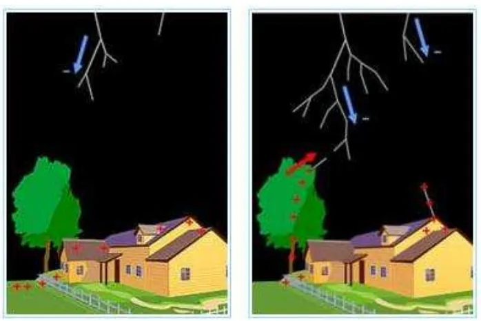
[image:18.612.140.525.316.579.2]There are several types of lightning that is produced by the thundercloud. The cloud discharge is one if the lightning type which happen in the cloud itself. Besides that, the lightning between could to cloud that occur between the one cloud and the other cloud), between cloud and the earth (cloud-to-ground or ground discharges) and also the air discharge which happen between the cloud and it air surrounding. Usually, the lightning can be classified mainly as ground flashes (CGs) and also cloud flashes (ICs) [3]. All the negative cloud to ground flashes brings the negative charge to the ground and 90% show from the electromagnetic field measurement [1].
6
2.3.Stepped Leader And Return Stroke
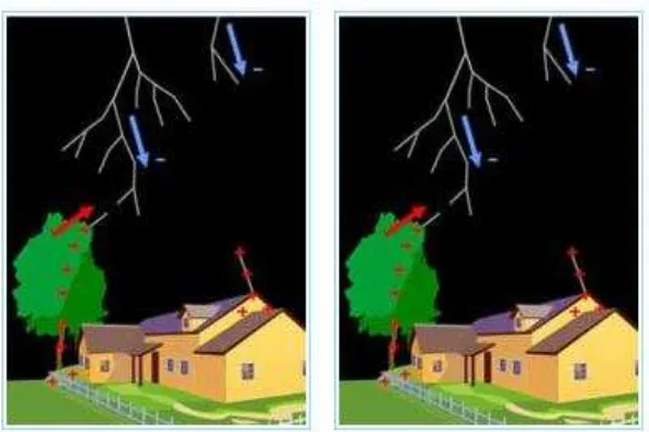
[image:19.612.150.499.316.549.2]Before the lightning strike to the ground, there was the activity happen in the cloud itself that is call preliminary breakdown. When the ionization of the atom in the cloud gained the electron (negative ions) and it will become electrically charged. When there was very strong value of negative charge in the cloud, which will produce the electric fields and will caused negative charge to be propelled downward to the earth. This phenomenon is called stepped leader because it appear downward to the earth (Figure 2.2). The stepped leader from the cloud come downward to the ground can be class as a series of branches or steps.
7
[image:20.612.176.472.340.537.2]When the lightning is near to the ground which contains positive ions, the negative ions from the cloud will be attract to the positive ions on the ground. The positive ion from the ground will cause the upward moving discharge from the ground to the cloud. This process is called the return stroke and the flash can be up 26 strokes but in average are only three to five strokes. This return stroke has very high emission radiation based on the previous experiment. In this return stroke there was fast front and also slow front that only happen in very short time. This to parameter is very important to know the effect of the return stroke to the equipment that is very sensitive.
8
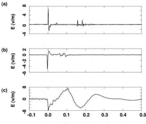
2.4.Narrow Bipolar Pulses (NBPs)
[image:21.612.204.447.385.591.2]Narrow Bipolar Pulses (NBPs) is also can be recognize and known as a compact of intracloud discharges (CIDs), [1][18] from the lightning process due to the association of the strong radio frequency (RF) radiation. There are two types of NBPs that are known as Narrow Positive Bipolar Pulses (NPBPs) and also Narrow Negative Bipolar Pulses (NNBPs). These NBPs was observed easily in the country that have the tropical region compared to the country that in temperate region, [1]. The other information, the positive NBPs was reported happen at the range of 6 km – 15 km while the negative NBPs at the higher range which is 15 km – 21 km, [1]. Besides that, this NBPs also known as very high power, short distance discharge of the radio waves which is produces the very strong emission radiation.
9
CHAPTER 3
3. METHODOLOGY
3.1.Flow Chart
10
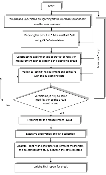
Figure 3.1: Flow Chart of the Project No
Familiar and understand on lightning flashes mechanism and tools
used for measurement
Verification, if NO, do some modification to the circuit
construction
Writing final report for thesis Extensive observation and data collection
Start Li te rat u re S tu d y
Preparing for the measurement layout Modeling the circuit of 3 MHz and Fast Field
using ORCAD simulation
Construct the experimental apparatus for radiation measurementsuch as antenna and electronic circuit
Validate: Testing the equipment and compare with the outstanding data
Analyze, identify and characterized lightning mechanism and do comparative study between the data collected
11
3.2.Circuit Simulation Using Orcad
3.2.1. 3 MHz
[image:24.612.197.520.311.473.2]For this 3MHz circuit, it only used the simple RLC circuit. The inductor 47uF was connected in series with the antenna capacitor 59p and 50 ohm matching resistor as Figure 3.2. From the result simulation as in Figure 3.3, the bandwidths for 3MHz in range 267 kHz.
Figure 3.2 : Equivalent Circuit for 3MHZ
[image:24.612.160.566.530.655.2]