ISSN: 1693-6930
accredited by DGHE (DIKTI), Decree No: 51/Dikti/Kep/2010 451
Ventilation Structure Improvement of Air-cooled
Induction Motor Using Multiphysics Simulations
Yujiao Zhang*1, Xiongfeng Huang1, Tao Huang2, Jiangjun Ruan2, Xiaowen Wu2 1
School of Electrical Engineering and Renewable Energy, China Three Gorges University 8 University Avenue, Yichang, Hubei province, P.R. China
2
School of Electrical Engineering, Wuhan University Luo-jia-shan Wuchang, Wuhan, Hubei Province, P.R.China
e-mail: [email protected]*1
Abstrak
Desain yang optimal dari motor induksi besar adalah proses yang melibatkan keterampilan listrik dan mekanik serta keterampilan tentang dinamika termal dan fluida. Di dalam perkembangan terakhir tentang teknik perancangan mesin, seorang perancang tidak dapat mengandalkan metode analisis standar. Dalam simulasi multiphysics yang dilakukan berdasarkan metode elemen hingga dengan kopling lemah, nilai batas rotasi pada antarmuka diantara celah udara dan rotor tidak dapat diterapkan langsung untuk analisis dinamika fluida. Sebuah metode multi-komponen fluida yang baru, diusulkan untuk mengatasi pengaruh dari putaran rotor pada konveksi udara. Tulisan ini menyelidiki sebuah simulasi model multi-fisika 3-D yang digunakan dalam simulasi temperatur terdistribusi di dalam udara pendingin motor induksi. Kenaikan suhu di motor dikarenakan kerugian Joule dalam gulungan stator, induksi arus eddy di dalam rangka kandang tupai, dan disipasi panas secara konveksi oleh konduksi udara dan material padat. Kerugian Joule yang dihitung dengan analisis medan eddy 3-D digunakan sebagai input untuk analisis medan termal , sangat tergantung pada analisis medan fluida udara yang akurat. Melalui perhitungan medan terkopling, struktur ventilasi baru untuk motor 15-fase telah diusulkan, sehingga kinerja pendinginan dapat meningkat.
Kata kunci: medan arus Eddy, metode elemen hingga (FEM), medan fluida, motor induksi asinkron berpendingin udara, simulasi Multiphysics
Abstract
Optimal design of large induction motor is a process that involves electrical and mechanical skills as well as thermal and fluid dynamic skills. For recent machine layouts, one cannot rely on standard analysis methods. In multiphysics simulations which are done by weak coupling finite-element method, rotation boundary values on interface between air gap and rotor cannot be applied directly for fluid-dynamical analysis. A novel multi-component fluid method is proposed to deal with the influence of rotor rotation upon the air convection. This paper investigates a 3-D multi-physics simulation used in simulation of temperature distribution in air-cooled induction motor. The temperature rise in motor is due to Joule’s losses in stator windings and the induced eddy current in squirrel cages, and heat dissipation by air convection and solid conduction. The Joule’s losses calculated by 3-D eddy-current field analysis are used as the input for the thermal field analysis, which deeply depends on accurate air fluid field analysis. Through the coupled-field calculation, we proposed a new ventilation structure of a 15-phase motor to improve the cooling performance.
Keywords: air-cooled asynchronous induction motor, Eddy current field, finite-element method (FEM), fluid field, Multiphysics simulation
1. Introduction
prediction of the temperature rise in each part of the machine will lead to the maximum exploitation of the materials and the highest performance of the machine [2]. Furthermore, the thermal analysis of induction motors, due to the complexity of air course and the influence of rotation upon air-flow, cannot be accurately evaluated by using traditional lumped circuits together with empirical curves method. Therefore, a coupled analysis of eddy-current, fluid and thermal fields is mandatory to compute the temperature rise [3].
Useful research has been carried out concerning cooling and ventilation of motors [4]. In the motors with the axial and radial ventilation system, axial fans are placed on both sides of the motor. Cooling air, taken in from the exterior to the interior by axial fans, is sent to exothermic parts. Then, the air is vented through the radial paths inside the iron core. Moreover, the influence of centrifugal force and Coriolis force caused by rotation upon air-flow in the air gap must be considered [3]. However, according to no-slip boundary condition in fluid dynamic theory, rotation velocity on interface between air gap and rotor cannot be applied directly. To deal with this problem in fluid field analysis, we proposed a novel multi-component fluid model, which all rotor parts are taken as fluids under some constraint conditions.
In the last decade years, the 2-D finite element method (FEM) is usually used to analyze the coupled electromagnetic-thermal fields, or coupled thermal-fluid fields in various motors [4]-[8]. Seldom, researches were carried out on coupled electromagnetic-thermal-fluid fields with 3-D FEM. The rotor rotation-effects on air convection have been investigated by equivalent thermal circuit [2].
Nevertheless, for the axial movement of air, end ring of squirrel cage and rotor rotation-effects on air convection, 2-D model is inadequate to achieve more accurate results. Therefore, an accurate ventilation system design of air-cooled induction motors requires 3-D coupled electromagnetic fluid and thermal field finite-element analysis, which is investigated in this paper.
In addition, in this paper, magnetic saturation and nonlinear resistivity with temperature are also taken into account. During the design stage of a 15-phase 14-pole 10MW a synchronous motor, according to the motor parameters provided by the motor designers, the 3-D model is established to calculate the temperature distributions. The results show that it is necessary to improve the ventilation structure to decrease stator windings temperature below the permissible insulation material temperature. Furthermore, the simulated results of the improved model with rotor axial paths are compared with those of original model. Then, the maximum temperature rise of stator windings decreases by 18%. Therefore, the cooling performance is improved.
2. Multi-component Fuild Methods
1 is the density of air, µ is the viscosity coefficient of air, p is the fluid pressure.
To deal with the restriction of no-slip boundary condition in fluid dynamic analysis, we proposed a multi-component fluid model which all rotor solid components (squirrel cage and iron core) are taken as fluids under constraint conditions as follows:
1) The velocity of squirrel cage and iron core only has tangential velocity, namely, vr=0, vθ=vθ(r), and ∂vθ/∂θ=0.
2) Ignoring gravity, the flow can be regarded as pure shear flow, and pressure is constant along the flow direction, namely, ∂p/∂θ=0.
Under the conditions above, the fluid equations of rotor component can be simplified as:
0
where ρ2 is the actual density of rotating parts. As shown, viscosity coefficient does not affect the results.
3. Research Method
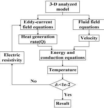
The flowchart of the entire analytical methodology is shown in Figure 1. Based on the 3-D FEM model of a motor, eddy-current and fluid simulations are carried out to obtain the losses of every element and air-flow velocity of every node. The thermal computation is tightly coupled to the electro-magnetic and fluid-dynamical results. The resistivity of stator windings and squirrel cage is updated in accordance to the thermal field calculation result until the maximum difference of temperature between two adjacent steps is less than 0.01℃ [11].
3.1. 3-D Eddy-Current Field Equations
Using Maxwell’s equations in which the magnetic vector potential and the electric scalar potential are introduced, the eddy-current field equations can be given as [9] [12]:
( )
( )
where V1 is the eddy current region (rotor squirrel cage), V2 is the source current region (stator windings), and V3 is the ferromagnetic material region (iron core of stator and rotor).
The basic principle of the nonlinear time-harmonic analysis considering magnetic saturation is to replace the DC B-H curve with the effective B-H curve [11]. With the effective permeability, µe, the saturation of ferromagnetic material can be taken into account in time-harmonic analysis.
Electrical resistivity is estimated from the following equation [12]:
( )
0(
1)
R T =R + ×C T (11)
where R0 is the resistivity at 0,C is temperature coefficient.
3.2. 3-D Fluid Field Equations
Because of the large Reynolds number (> 2300), the fluid gets turbulent. The standard k-ε turbulence model was used in the turbulence calculation. The equations are written as [13]
( ) (
ρ ρ)
µ µ ρε dissipation is mainly due to air convection and solid conduction. In addition to the fluid equations, the energy equation must be solved as well [9].For the stator windings and iron core, the steady state heat conduction equation for solid is given as [14]:
( x ) ( y ) ( z )
T T T
k k k Q
x x y y z z
∂ ∂ + ∂ ∂ +∂ ∂ = −
∂ ∂ ∂ ∂ ∂ ∂ (16)
where kx, ky, and kz are the coefficient of heat conductivity in the x-, y- and z- directions, respectively.
Two types of boundary condition are used in this study. In the computational domain, the heat transfer coefficient of surface between air and rotor components can be obtained by coupled iteration of fluid, energy and conduction equations, so that the convection condition need not be applied. However, in the outer surface of stator core, the convection condition can be represented as [6] [13]:
(
0)
0 Tk h T T n
∂ + − =
∂ (17)
where h is the heat transfer coefficient, and T0 is the air temperature.
4. Simulation Results and Analysis of A 15-phase Motor 4.1. 3-D Multiphysics Simulation
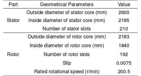
A 15-phase 14-pole 10MW a synchronous motor structure is during the design stage. According to the parameters provided by designers, the 3-D calculation model has been built, as shown in Figure 2(a). Although the influence of end windings cannot be ignored because of the complexity of its structure and large amount of computation, it was not considered temporarily in this study stage. The model is meshed with prism-shaped elements, as shown in Figure 2(b) and (c). There are 1,106,786 elements and 565,989 nodes. Tables 1 and 2 give the main geometrical and material properties of the model, respectively.
(a) 3-D Partial model of 15-phase motor
(b) Finite-element model (c) Partial enlarges of finite-element model
Figure 2. the 3-D calculation model
Table 1. Main Geometry Value of the Analyzed Model
Part Geometrical Parameters Value
Stator
Outside diameter of stator core (mm) 2600
Inside diameter of stator core (mm) 2195
Number of stator slots 210
Rotor
Outside diameter of rotor core (mm) 2183
Inside diameter of rotor core (mm) 1840
Number of rotor slots 192
Slip 0.0075
Table 2. Material Data of the Analyzed Model
* T is temperature of the copper conductor ( )
In the computation of the eddy-current field, the rated source current is 343.4 A. The rated frequency of current is 23.57 Hz. Considering the influence of rotor rotation, the frequency (f) is converted into f×slip. In the computation of the fluid and thermal field, total air volume of design is 4.54 m3/s, and pressure on outlet boundary is defined as a standard atmospheric pressure. The rated rotational speed was applied to rotor and shaft. Considering the low conductivity of insulation material, the thermal conductivity of stator windings is anisotropic. The ambient temperature is set to 25 0C.
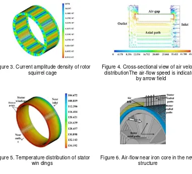
Figure 3. Current amplitude density of rotor squirrel cage
Figure 4. Cross-sectional view of air velocity distributionThe air-flow speed is indicated
by arrow field
Figure 5. Temperature distribution of stator win dings
Figure 6. Air-flow near iron core in the new structure
vector graph on a cross section of the 3-D model. With a significant influence of rotor rotation, the movement of air on outlet is diffuse. Figure 5 illustrates the temperature distribution, which has the maximum on the stator windings near the outlet of air.
4.2. Ventilation Structure Improvement
To improve the cooling performance, we proposed a different ventilation structure. As shown in Figure 6, there are radial paths in the stator and rotor iron cores. Air flows from rotor axial paths to rotor radial paths, air gap and stator radial paths, and then to the outside of the stator iron core.
With the same electromagnetic loading condition, the coupled-fields of the new model are calculated using the methodology mentioned in Section 2. In addition, the ventilation mode is changed because of the structure. In the motors with the axial and radial ventilation system, axial fans are placed on both sides of the motor. With the same total air volume, fluid field is simulated.
Figure 7. Flux density distribution in air gap Figure 8. Cross-sectional view of air velocity distribution
(a) Temperature distribution of shaft (b) Temperature distribution of stator windings
Figure 9. Thermal results
Table 3. Thermal Class Designation
Temperature(℃) Thermal class designation
90 90
105 105
120 120
130 130
155 155
180 180
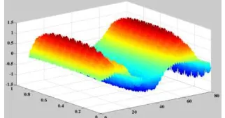
Figure 7 shows the flux density in air gap. It presents the radial ventilation ducts have effect on the air-gap flux density. In order to show the air movement clearly, Figure 8 gives the fluid field pattern on cross sections of the 3-D model. The air velocity distribution in each radial ventilation duct is identical. From the results of temperature, the maximum temperature of stator windings is 115 0C, as shown in Figure 9.
insulation systems-Thermal classification), as shown in Table 3, the permissible insulation material thermal classification reduces from class 130 to class 105. Thus, it is found that the cooling performance of new motor is improved by the ventilation structure with rotor axial paths.
5. Conclusion
This paper proposes a 3-D coupled-field analysis to predict temperature distribution in large air-cooled a synchronous induction motor. Furthermore, a novel multi-component fluid model is proposed to deal with the influence of rotor rotation upon the air convection. For a motor during design stage, we put forward a new ventilation structure with radial paths to improve the cooling performance. It is proved that the axial and radial ventilation system has better cooling effectiveness for large electrical machine.
References
[1] Nyambayar Baatar, Shiho Kim. A Thermoelectric Generator Replacing Radiator of Internal Combustion Engine Vehicles. TELKOMNIKA. 2011; 9(3): 523-530.
[2] Luigi Alberti, Nicola Bianchi. A Coupled Thermal-Electromagnetic Analysis for a Rapid and Accurate Prediction of IM Performance. IEEE Transactions on Industrial Electronics. 2008; 55(10): 3575-3582. [3] F Marignetti, V Delli Colli, Yuri Coia. Design of Axial Flux PM Synchronous Machines Through 3-D
Coupled Electromagnetic Thermal and Fluid-Dynamical Finite-Element Analysis. IEEE Transactions on Industrial Electronics. 2008; 55(10): 3591-3601.
[4] Takafumi Nakahama, Debasish Biswas, Koichiro Kawano. Improved Cooling Performance of Large Motors Using Fans. IEEE Transactions on Energy Conversion. 2006; 21(2): 324-331.
[5] W N Fu, S L Ho. A 2-Dimensional Finite-Element Method for Transient Magnetic Field Computation Taking Into Account Parasitic Capacitive Effects. IEEE Transactions on Applied Superconductivity. 2010; 20(3): 1869-1873.
[6] E Dlala, A Arkkio. A General Model for Investigating the Effects of the Frequency Converter on the Magnetic Iron Losses of a Squirrel-Cage Induction Motor. IEEE Transactions on Magnetics. 2009; 45(9): 3303 – 3315.
[7] M J Islam, H V Khang, A K Repo. Eddy-Current Loss and Temperature Rise in the Form-Wound Stator Winding of an Inverter-Fed Cage Induction Motor. IEEE Transactions on Magnetics. 2010; 46(8): 3413-3416.
[8] S Mezani, N Takorabet, B Laporte. A combined electromagnetic and thermal analysis of induction motors. IEEE Transactions on Magnetics. 2005; 41(5): 1572-1575.
[9] S. L. Ho, Y. Li, X. Lin. Calculations of eddy current, fluid, and thermal fields in an air insulated bus duct system. IEEE Transactions on Magnetics. 2007; 43(4): 1433-1436.
[10] S L Ho, Y Li, X Lin. A 3-D study of eddy current field and temperature rises in a compact bus duct system. IEEE Transactions on Magnetics. 2006; 42(4): 987-990.
[11] Y J Zhang, J J Ruan, Tao Huang. Calculation of Temperature Rise in Air-cooled Induction Motors through 3-D Coupled Electromagnetic Fluid-Dynamical and Thermal Finite-Element Analysis. IEEE Transactions on Magnetics. 2012; 48(2): 1047-1050.
[12] Didi Istardi, Andy Triwinarko. Induction Heating Process Design Using COMSOL Multiphysics Software. TELKOMNIKA. 2011; 9(2): 327-334.
[13] A G Jack, B C Mecrow. Methods for Magnetically Nonlinear Problems Involving Significant Hysteresis and Eddy currents. IEEE Transactions on Magnetics. 1990; 26(2): 424-429.
[14] J H Yoon, H S Ahn, J Choi. An estimation technology of temperature rise in GIS bus bar using three-dimensional coupled-field Multiphysics. 2008 IEEE International Symposium on Electrical Insulation. Vancouver. 2008; 1: 432-436.
[15] W L Li, S Y Ding, H Y Jin. Numerical calculation of multi-coupled fields in large salient synchronous generator. IEEE Transactions on Magnetics. 2007; 43(4): 1449-1452.


