(will be inserted by the editor)
A planar Penning trap
S. Stahl1, F. Galve1,2, J. Alonso1,2, S. Djekic1, W. Quint2, T. Valenzuela1, J. Verd´u1, M. Vogel1 and G. Werth1
1
Institut f¨ur Physik, Johannes-Gutenberg-Universit¨at, D-55099 Mainz, Germany
2
GSI, D-64291 Darmstadt, Germany
Received: date / Revised version: date
Abstract. We present a new concept for a Penning trap, which is planar and allows for the implemen-tation of novel confinement techniques. The trap provides confinement perpendicular to its plane by an electric potential minimum while a superimposed magnetic field provides radial confinement. Both the axial position and the depth of the potential minimum can be controlled by the applied voltages. The device is scalable in the sense that an arbitrary number of planar traps can be embedded in one plane thus representing a multitrap array which can be used for particle interaction studies. Switches between different traps in the planar array allow for controlled interactions between the single stored particles.
PACS. 85.35.Gv Single electron devices – 07.20.Mc Cryogenics and low temperature equipment – 07.50.-e Electronic intruments and components – 07.90.+c Other topics in instruments
1 Introduction
Penning traps confine charged particles by a combina-tion of static electric and magnetic fields [1–3]. The electric field provides a potential minimum in one direction, com-monly called the z-direction. The defocusing force of this field in the plane perpendicular to the z-axis is compen-sated by a magnetic field directed along the z-axis. When operated under ultra-high vacuum conditions virtually un-limited times for confinement of charged particles such as electrons and protons and their antiparticles as well as singly or multiply charged ions have been achieved. Pen-ning traps have been successfully used in the determina-tion of fundamental constants [4, 5], high precision mass spectrometry [6–9], or Zeeman spectroscopy [10–12].
In a similar way their counterpart, the Paul trap, which uses only time varying electric fields to produce a time av-eraged potential minimum, has been applied to precision spectroscopy such as hyperfine measurements [13], lifetime determination of long lived metastable ionic energy levels [14–17], and the development of frequency standards [18]. More recently Paul traps have proven to be potentially useful tools in the development of quantum computation [19, 20]. In this context planar Paul traps have been de-veloped which offer interesting possibilities in the study of multipartite systems and entanglement [21].
In this article we discuss the properties and possible applications of a planar Penning trap. We will first de-scribe the general idea of this device in comparison to conventional Penning traps. A particular feature of pla-nar Penning traps is the possibility of miniaturisation and the formation of 2D trap arrays, which may be useful when coupling of several single particles is the issue. Trap arrays
and the coupling mechanism will be discussed in more de-tail in the third section of the paper.
2 Planar trap
A conventional 3D Penning trap consists of two elec-trically connected endcap electrodes at a distance 2z0and one ring electrode of radiusr0. When the surfaces of the electrodes follow hyperboloids of revolution, the potential in the space between the electrodes depends on the square of the coordinates and therefore has a quadrupolar shape. It has the expression:
Φ(x, y, z) = U 2d2
0
(x2+y2−2z2) (1)
whereU is the potential difference between ring and end-cap electrodes andd0a characteristic trap dimension. The equation of motion of a charged particle in this
poten-Fig. 1.Planar trap scheme. The electrodes (black) are embed-ded in a plane made of an isolator.
magnetron frequencies. When the electrode shape deviates from the hyperbolic form, the dependence of the potential on the coordinates will be different. As long as rotational symmetry with respect to thez-axis is preserved, the po-tential can easily be expanded in spherical harmonics and the leading term remains the quadrupole part.
Converting the three-dimensional electrode array into a two-dimensional one is achieved by removing the upper endcap and embedding the ring and lower endcap in a plane. The result is displayed in figure 1. This is the sim-plest 2D configuration possible. Further ring electrodes may be added if necessary to enhance the properties of the trap. This case will be discussed in section 2.1.
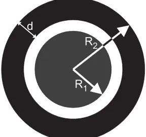
Fig. 2.Geometry parameters of the planar trap.
Mechanically the electrodes of a planar trap can be implemented by use of well-established thin film or thick film technology on a ceramic substrate, e.g. using gold as electrode material. Thick film technology has been in use since decades, giving spatial resolution in the order of 20µm, whereas thin film technology achieves even sub-µm resolution. To avoid charge accumulation on the substrate and the corresponding disturbing influences on the trap-ping behavior, an additional surface layer of low conduc-tivity can be used. Thin layers of e.g. graphite or gold in the high MΩ-region avoid a charging-up, yet isolate the electrodes sufficiently to avoid shortcuts. The electrodes are connected to the respective voltage supplies by con-tacts through the substrate.
In contrast to conventional Penning traps the planar trap represents an open geometry. This allows to access the trapped particles with any kind of radiation or beam and avoids to a large extent the occurance of ”cavity ef-fects” which may affect the damping of the oscillation modes [22]. This is of particular importance for the cy-clotron mode in the case of stored electrons. Moreover, the position of the trapped particles as well as the depth of the potential can be varied to a certain extent by appro-priate choice of the applied voltages, as will be discussed below.
2.1 Shape of the trapping potential
The electrostatic potential for a fixed set of parameters exhibits a minimum at a well-defined distance above the trap’s plane. This minimum serves for axial confinement of a charged particle, while radial confinement is assured by the magnetic field along thez-direction, as in conventional Penning traps.
The electrostatic potential of a cylindrically symmet-ric configuration can always be expressed by the linear combination
∞
0 dk
A(k)e−kz+B(k)ekz
(J0(kρ) +C(k)N0(kρ))
with Jν and Nν being the standard Bessel functions of
first and second kind, respectively[23]. In our case ν = 0 because of cylindrical symmetry. A particle trapped in the regionz >0 feels a potential of the form
φ(z, ρ) = ∞
0
dk A(k)e−kzJ0(kρ), (2)
where the terms withB(k), C(k) have been dropped be-cause they diverge forz→ ∞andρ→ ∞, respectively. In order to obtain the coefficientsA(k) we impose the values of the potential in the planez= 0
V(ρ)≡φ(0, ρ) = ∞
0
dk A(k)J0(kρ) (3)
which, by use of the Hankel transform [23], allows for writ-ing
A(k) =k ∞
0
dρ ρ V(ρ)J0(kρ). (4) AsV(ρ) is piecewise constant, the coefficients A(k) are a sum of the contributions from each electrode:
A(k) =
i
Ai(k) (5)
with
Ai(k) =Vi[RiJ1(kRi)−(Ri−di)J1(k(Ri−di))] (6)
where Ri denotes the distance at which electrode i ends
and di its thickness. Thus, the central electrode ends at
R1, the inner ring electrode atR2 and so forth.
should understand that a probable physical implementa-tion of this trap would have a grounded ring electrode as an external one, in addition to the ”active” electrodes).
Based on the coefficients A(k) one can integrate the potential in the whole space by using expression (2). As we are interested in confinement along thez-axis the desired solution is obtained by
φ(z,0)≡φ(z) = ∞
0
dk A(k)e−kz, (7)
which is an analytic expression and represents a sum of contributions from each electrode of the type
φi(z) =Vi
The potential of eq.(8) describes a trap with as many ad-jacent electrodes as desired (one disk and many rings), but in this paper we will consider only the possibility of hav-ing either 2 or 3 electrodes plus an external rhav-ing electrode which is grounded and ensures that our approximation is sufficiently correct. The condition that the electrodes are adjacent can be written as
Ri+1=Ri+di+1
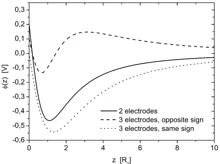
In figure 3, the resulting axial potentials for three simple choices of the electrode voltages are shown. The solid line represents the shape of the axial potential for the most simple case of two electrodes (central electrode and one ring electrode as shown in figure 2, V1=0.2 V, V2=-2 V). The dotted line shows a case with an additional ring
elec-Fig. 3.Axial potential as a function of the axial position mea-sured in units of the inner electrode radius for three distinct cases of applied voltages. For details, see text.
trode outside the above configuration when the two ring electrodes have voltages of the same sign (V1=0 V, V2 =-1 V, V3=-2 V). Qualitatively, this configuration leads to the same potential shape as in the case with two elec-trodes, as one might expect. The dashed line gives the ax-ial potentax-ial for the the same geometry, but with the two
ring electrode voltages having opposite signs (V1=0.1 V, V2=-2 V, V3=3 V). In this case, both a maximum and a minimum occur. The shape of the minimum is changed as compared to the other configurations, affecting also the harmonicity, as will be discussed in the following section.
2.2 Harmonicity of the trapping potential
The established methods of detection and manipula-tion of trapped particles as relevant in the present case rely on well-defined motional frequencies. Presently, the axial frequency is of special interest. It is thus important to produce an axial trapping potential as harmonic as pos-sible.
Let the anharmonicity be defined by the relative axial frequency difference between the particle at a finite mo-tional energy and the ground energyE0=12ωz,
κ(E) := ωz(E)−ωz(E0) ωz(E0)
. (9)
Then the anharmonicity is given by
κ(E) =
being the motional amplitude of the particle along the z-direction andCi being the coefficients of the electrostatic
potential as expanded by
A shift in axial frequency due to the anharmonicity of the trapping potential may obstruct a measurement of the corresponding signal. Detection of the particles’ axial motion can be performed by pickup of the induced image current in the central trap electrode via a tuned resonance circuit of quality factorQ[29]. The width∆ωz of the
sig-nal after transformation to the frequency domain is given by the inverse time cooling constant due to the resistivity R of the detection electronics. The cooling time constant is given by
τ= mD 2
q2R (13)
where m is the particle mass, D is the effective distance of the particle to the electrode surface,q is the particle’s charge. The resistanceR is given by
R= Q
ωzC
, (14)
Fig. 4.Potential minimum in the range of an electron oscillat-ing at T=100 mK withωz ≈100 MHz. The electrode voltages have been chosen toV1=0 V,V2=-1 V andV3=2.6108 V.
at an axial frequency of 100 MHz with detection electron-ics of Q=300 and C=7.5 pF the width ∆ωz of the axial
signal is around 1 kHz. The anharmonicity κ(E) of the trapping potential needs to fulfill the relation
κ(E)ωz(E)∆ωz. (15)
Thus, at an axial frequency of 100 MHz, anharmonicities κin the 10−5 region are necessary to allow for a reliable measurement of the axial signal.
An example of the shape of the trapping potential for a given choice of electrode voltages and geometries is given in figure 4. It represents the potential minimum in the range of an electron oscillating at T=100 mK with ωz ≈100 MHz. The electrode voltages have been chosen
to V1=0 V, V2=-1 V and V3=2.6108 V. A comparison of the calculated potential shape with a harmonic potential yields an anharmonicity κ of roughly 4·10−6, which is sufficient for a reliable measurement of the axial signal.
2.3 Position of the minimum
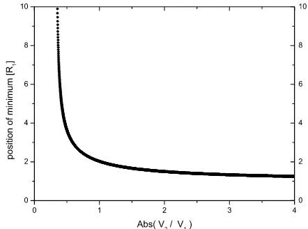
For a given geometry the position of the potential min-imum (z0) can be chosen by the applied voltages. Even though an analytic solution for the potential function is known, the determination of its minimum implies solving a transcendental equation. It is thus necessary to extract this information numerically.
Figure 5 shows the case with two electrodes, in which the minimum distance z0 is roughly given by the radius of the central electrode R1. With three electrodes it is possible to shift the position of the minimum in a wider range. When the two ring voltages are of opposite sign, it is possible to change both the position of the minimum (by changing V3 as compared to V2) and also its depth (by changing the absolute values of bothV2andV3). This situation is displayed in figure 6 for three choices of volt-ages leading to three different positions of the minimum z1,z2 and z3. However, when the minimum is shifted
to-Fig. 5.Position of the potential minimum in units of the inner electrode radius as a function of the applied voltage ratio in the case with 2 electrodes.
Fig. 6. Electrostatic potential as a function of z for three
different choices of the applied voltages.
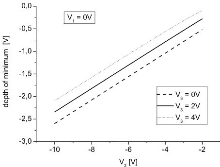
2.4 Depth of the minimum
The depth of the potential minimum determines the maximum energy of the particles that allows for trapping. In the case with two electrodes it shows a linear
depen-Fig. 7. Depth of the potential minimum as a function of the inner ring voltageV2 for three cases of the outer ring voltage V3 when the central electrode voltage isV1= 0V.
dence on the ring voltage and is of similar size. When three electrodes are being used, the overall linearity gen-erally disappears and is replaced by regions of linearity interconnected by regions with different shape, depend-ing on the exact positions and magnitudes of the super-imposed potential contributions from different electrodes. Thus, the precise potential depth has to be evaluated in detail for the given set of parameters. Figure 7 shows the depth of the potential minimum as a function of the inner ring voltageV2for three cases of the outer ring voltageV3 when the central electrode voltage is V1 = 0V. The be-havior is nearly linear in each case, however the magnitude of the depth depends on the choice ofV3.
3 Trap-trap interaction
By connecting a pair of planar traps as sketched in fig-ure 8 one obtains a system of individually trapped, inter-acting particles. Each oscillating particle induces a charge in the central electrode of its trap which interacts via a connecting line with the other particle. This type of inter-action has been studied before in [24, 25], however, for the present purpose, a different approach is discussed. We as-sume that the induced charges are located on both surfaces of each central electrode and that the electrode thickness is negligible. Let the upper surfaces of the central elec-trodes have a common radiusRand carry chargesQ1and Q2, respectively, while the remaining system, i.e. the two lower surfaces and the connecting wire, carries a common
Fig. 8.Both traps are connected with a connection line, which enables the induced charges to exchange energy between dif-ferent trapped particles. The interaction can be turned on and off by a switch.
where q is the charge of a trapped particle, Hi are the
particle Hamiltonians (which are effectively harmonic os-cillators),Ci are the capacitances of the surfaces, andzi
is the axial positions of the particles.
If the induced charges are driven adiabatically by the oscillating particles (i.e. they are in every moment in equi-librium with the oscillating particle) we can write:
d(H−H1−H2) dQi
= 0 ∀i (17)
By applying this relation we obtain Q1 and Q2 as func-tions of the zi, which inserted in the Hamiltonian (16)
yields:
H =H1+H2+Hint (18)
withHintbeing a function of bothzi. The system can be
quantised via the spatial variables of the axial oscillators, that iszi=z0+ ˜zi wherez0 is the minimum of the axial electrostatic potential. The ˜zi can be expressed with
lad-der operators describing the levels of the axial harmonic oscillator:
The hamiltonian for the system in the interaction picture to first order in ˆzi and in terms of the ladder operators
and C3 = 2C1+Cwire ∼ 2C1, we obtain the expression for the interaction frequency:
ωint=
q2 16πR3ǫ
0 1 2mωz
1− z0 R2+z2
0 2
. (21)
The interaction frequency is very sensitive to the length scales of the trap; to give an example, an electron confined in this configuration would have an interaction frequency
ωint≈102
1 ωzR3
1− z0 R2+z2
0 2
(22)
with z0, R given in meters and the frequencies given in Hz. If z0 ≈ R and R ≈ 1 mm then ωint is of the order
of 1010 ωz s
−2, i.e. for an axial frequency of 1 MHz the effec-tive interaction frequency is 10 kHz. If R ≈0.1 mm then ωint ≈ 10
13
ωz s
−2, i.e. for an axial frequency of 1 MHz the interaction frequency is 10 MHz. The quantity in brackets in equation (22) gives the dependence on the distance z0 and can vary the strength of the interaction by several orders of magnitude. For example, forz0/R= 1 the quan-tity in brackets is about 0.1. Already for z0/R= 10 the same quantity is 2×10⁻⁵.
This means that even for a fixed trap geometry, it is still possible to control the speed of interaction within a certain range by moving the particles along the z direc-tion. This can be achieved via control of the position of the electric minimum, as described in section 2.3. Note, that particle interaction does not rely on a connection line as it is assumed in the above discussion. Alternatively, one can also use the direct Coulomb interaction of the trapped particles and choose the interaction strength by geomet-ric parameters and the detuning of the axial frequencies. Having both methods available can help studying which of them is more robust against decoherence.
4 Array of traps
One major advantage of the novel trap being planar is the possibility to arrange several traps in a plane. This would be the equivalent to the optical lattices used as multitraps in other experiments. The advantage compared to a possible linear array of Penning traps along the z-axis is due to the change from one spatial dimension (1D) to two (2D), since at a given length scale of order L, the number of traps in an array scales not with L, but with L2. This opens up the possibility of implementing a large number of traps in parallel.
5 Possible applications
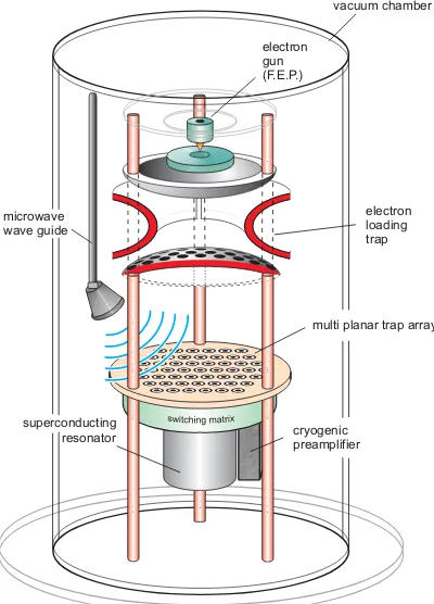
Figure 10 shows a schematic representation of an ex-perimental setup for an array of planar traps used for elec-tron confinement. The setup consists of a field emission
Fig. 9.Example of a 2D-array of planar traps connected by a switching matrix with an information exchange rail.
point (FEP) as a source of electrons. A conventional hy-perbolic Penning trap with a mesh as lower endcap is used for storage and preparation of the electrons to be trapped in the planar trap array. It is used to create a ”shower” of a large number of electrons (≈109) onto the planar array by appropriate pulsing of the ring electrode voltage. Even with a capture efficiency of less than 10−4 it will thus be possible to trap some 103 electrons per trap. This
num-vacuum chamber
superconducting
resonator cryogenic
preamplifier microwave
wave guide
electron loading trap electron
gun (F.E.P.)
multi planar trap array
ber may then be lowered to one by use of well-established mechanisms (see e.g. [26]). Coupling of a number of single electrons may be performed by use of a switching matrix. A microwave source can be used in order to induce spin flips of the electron spin. When the device is used in a cryogenic surrounding, synchrotron radiation in the cy-clotron motion of the electrons in the external magnetic field of several Tesla strength provides fast cooling of the cyclotron motion [27]. By coupling of the cyclotron de-gree of freedom to the axial motion, also the axial dede-gree of freedom can be cooled efficiently [28].
Detection of the electron’s motion in a trap is achieved by detection of the image charge induced in the trap elec-trodes and the corresponding image current through the attached electronics [29]. A Fourier transform of the de-tected signal then yields the motional frequencies. The detection can be performed separately for the different motional degrees of freedom of the electron in analogy to similar measurements performed on single stored ions [26, 28, 30].
5.1 Single-particle measurements in parallel
It is commonly known that numerous experiments con-cerned with spectroscopy, atomic state lifetime measure-ments, mass- and g-factor precision measuremeasure-ments, fre-quency standards and many more gain substancially from employing trapping techniques. However, typically only one measurement is performed at a time since only one trap and/or one particle is employed. Planar traps may add some features to these kinds of investigations, since a 2D array of planar traps can be used for a simultaneous measurement of the same particle property in a large num-ber of identical particles that are trapped and addressed individually. Measurement statistics is thus increased pro-portionally to the number of traps in use, limited virtually only by miniaturisation and electronics. Problems may arise from inhomogeneities of the magnetic field leading to slightly different values of the field strength in different traps. Field inhomogeneities of superconducting solenoids are typically as small asµT/mm2or below, but might still influence high-precision measurements. However, a num-ber of measurements is not sensitive to the absolute value of the field strength since only frequency ratios are mea-sured, see e.g. the g-factor precision measurements as de-scribed in [26, 28]. In these cases a shortening of the neces-sary measurement time by a factor√nwhennis the num-ber of parallel measurements would be most welcome since it could help to reduce measurement time from months to weeks or to reduce the statistical uncertainty accordingly.
5.2 Single-trap quantum logic and controlled particle interaction
It has recently been achieved to implement quantum informational gates and algorithms with trapped ions [19, 20, 31–33]. The control over trapped particles and the nat-ural long coherence time that a trap provides to quantum
superpositions makes this tool desirable for developments in the field. It has recently also been proposed to use stored electrons for quantum information processing [34, 35]. When a planar trap array is used for storage of single electrons at sufficiently low temperature, it appears pos-sible to perform quantum logic with each single trapped electron as described in detail in [34, 35], with two qubits per trap comprising two internal (spin) states and the ex-ternal (quantized motion) states, preferably the ground state and the first excited state of the axial and cyclotron motion. Under the present conditions, at ambience tem-peratures below 100 mK as reached in 3He-4He dilution refrigerators, the electronic synchrotron radiation brings the electron into the ground state of the cyclotron motion [22]. The ground state of the axial motion may then be reached by coupling of the two motions. Control over the the spin state is assured by the possibility of inducing a spin flip by irradiation of appropriate microwaves. Detec-tion of the spin state is performed by use of the ”Contin-uous Stern-Gerlach effect” which measures the spin state by the corresponding axial frequency (for details on this technique see, e.g. [26, 28]). The reader should note that the resonant circuit detecting the axial frequency is tuned off (switched off) during logic operation so that spin’s co-herence is not affected; readout is applied only at the end. The present Penning trap design yields furthermore the possibility to employ an array of single-electron traps with switchable interconnections between individual traps. The control over the interaction strength (or speed) of particles in different traps allows for studies of interaction effects and controlled coupling of different motional de-grees of freedom of the particles. The interconnection of a number of one-electron two-qubit systems might make it possible to implement also quantum registers and error correction strategies as described in [34, 35].
6 Conclusions
We have proposed a design for a planar Penning trap which can be scaled down to the sub-mm range. We have shown that the design allows for particle trapping and control over the position and the depth of the potential minimum by choice of the applied voltages. An arbitrary number of such traps may be arranged on a substrate chip and connected by cryogenic switches. The fact that an arbitrary number of traps can be arranged in 2D is an advance in the scalability of trapping devices. It has in addition the virtue of allowing for a number of parallel measurements of the same quantity in the study of single-particle properties, which increases the statistical signif-icance of any observable. The possibility of a controlled interaction between different traps by use of a switching matrix provides a powerful tool for particle interaction studies.
References
1. F.M. Penning, Physica (Utrecht)3, 873 (1936)
2. P.K. Ghosh,Ion traps, International series of monographs on physics 90, Oxford at Clarendon Press, 1995, ISBN 0-19-853995-9
3. L.S. Brown and G. Gabrielse, Rev. Mod. Phys. 58, 233 (1986)
4. R.S. Van Dyck, P.B. Schwinberg and H.G.Dehmelt, Phys. Rev. Lett.59, 26 (1987)
5. T. Beier et al., Phys. Rev. Lett.88, 011603 (2002) 6. F.L. Moore, D.L. Farnham, P.B. Schwinberg and R.S. Van
Dyck, Nucl. Instr. Meth. B43, 425 (1989)
7. E.A. Cornell et al., Phys. Rev. Lett.63, 1674 (1989) 8. G. Bollen, R.B. Moore, G. Savard and H. Stolzenberg, J.
Appl. Phys.68, 4355 (1990)
9. C. Gerz, D. Wilsdorf and G. Werth, Z. Phys. D 17, 117 (1990)
10. G. Tomaseo et al., Eur. Phys. J. D25, 113 (2003) 11. D.J. Wineland et al., Phys. Rev. Lett.50, 628 (1983) 12. J. Verd´u et al., Phys. Rev. Lett.92, 093002 (2004) 13. G. Savard and G. Werth, Ann. Rev. Nucl. Part. Sci.50,
119 (2000)
14. M. Knoop et al., Eur. Phys. J. D50, 163 (2004)
15. M. Block, O. Relm, P. Seibert, G. Werth, Europhys. Lett.
33, 595 (1996)
16. P.A. Barton et al., Phys. Rev. A62, 032503 (2000) 17. P. Staanum et al., Phys. Rev. A69, 032503 (2004) 18. P. Gill et al., Meas. Sci. Technol.14, 1174 (2003) 19. D.J. Wineland et al., Phil. Trans. Royal Soc. London A
361, 1349 (2003)
20. F. Schmidt-Kaler et al., Appl. Phys. B77, 789 (2003) 21. D. Kielpinski, C.R. Monroe and D.J. Wineland, Nature
417, 709 (2002)
22. S. Peil and G. Gabrielse, Phys. Rev. Lett.83, 1287 (1999) 23. M. Abramowitz and A. Stegun,Pocketbook of
mathemati-cal functions, Frankfurt/Main (1984)
24. D.J. Heinzen and D.J. Wineland, Phys. Rev. A 42, 2977 (1990)
25. A.S. Sørensen et al., Phys. Rev. Lett.92063601 (2004) 26. G. Werth, H. H¨affner and W. Quint, Adv. At. Mol. Opt.
Phys.48, 191 (2002)
27. S. Djekic et al., submitted to Eur. Phys. J. D 28. H. H¨affner et al.,Eur. Phys. J. D22(2003) 163
29. D.J. Wineland and H. Dehmelt, J. Appl. Phys. 46, 919 (1975)
30. M. Diederich et al., Hyp. Int.115, 185 (1998)
31. J. I. Cirac and P. Zoller, Phys. Rev. Lett.74, 4091 (1995) 32. Q.A. Turchette et al., Phys. Rev. Lett.81, 3631 (1998) 33. D. Leibfried et al., Nature422(2003) 412
34. S. Mancini, A. Martins and P. Tombesi, Phys. Rev. A61, 012303 (2000)