DOI: 10.12928/TELKOMNIKA.v13i3.1809 996
A Fractal Image Compression Method Based on
Multi-Wavelet
Yan Feng*, Hua Lu, XiLiang Zeng
Hunan University of International Economics, Changsha 410205, Hunan, China *Corresponding author, e-mail:[email protected]
Abstract
How to effectively store and transmit such multi-media files as image and video has become a research hotspot. The traditional compression algorithms have a relatively low compression ratio and bad quality of decoded image, at present, the fractal image compression method with a higher compression ratio fails to meet the requirements of the practical applications in the quality of the compressed image as well as the coding and decoding time.This paper integrates fractal thought and multi-wavelet transform and proposes a fractal image compression algorithm based on multi-wavelet transform. To transform the image model into a combination of relevant elements in the frequency domain instead of merely building on the foundation of the neighborhood gray-scale correlation has the ability to code larger image blocks, eliminates the possibility of global correlation in the image and improves the coding speed of the existing fractal image compression algorithm. The experimental result shows that the algorithm proposed in this paper can accelerate the coding speed of the present fractal image compression and have certain self-adaptivity while slightly reducing the quality of decoding image.
Keywords: multi-wavelet, fractal theory, image compression
Copyright © 2015 Universitas Ahmad Dahlan. All rights reserved.
1. Introduction
The image compression technology is a technique to use as few bits as possible to express the image signal from the information source to loweras much resource consumption such as the frequency bandwidth occupied by the image data, the storage space and the transmission time as possible for the sake of the transmission and storage of image signal. In fact, there exists strong correlation between the image pixels and such correlation has brought plenty of redundant information to the image, which makes image compression possible [1]. As a new image compression algorithm developed in the past decade, fractal image compression method attaches great importance to digging the self-similarity in most images and realizes the coding of an image with complicated visual characteristics on the surface via limited coefficients by using the iterated function system and some simple iteration rules. By using these rules, the decoder can realize the iterative decoding of the original image, therefore, the fractal image compression algorithm can achieve a highercompression ratio than other image compression algorithms [2].
Therefore, people start to apply wavelet transform in the image compression and they have achieved some results. As a development of single wavelet, multi-wavelet has such excellent properties as symmetry, orthogonality, short support and second-order vanishing moments, therefore, it has the advantages over single wavelet in the image processing and it can provide a more accurate analysis method [4, 5].
Based on the research in the relevant literature, this paper investigates the integrated method by introducing the multi-wavelet transform and integrating the separate advantages of wavelet coding and fractal coding. This paper, firstly, analyzes the principle and realization of fractal image compression coding. Then, it discusses the multi-wavelet decomposition and reconstruction of 2D images. Based on the above-mentioned research, the experiment simulation and analysis verify the effectiveness and practicability of this algorithm in this paper.
2. Fractal Image Compression Coding 2.1. Basic Principle of Image Compression
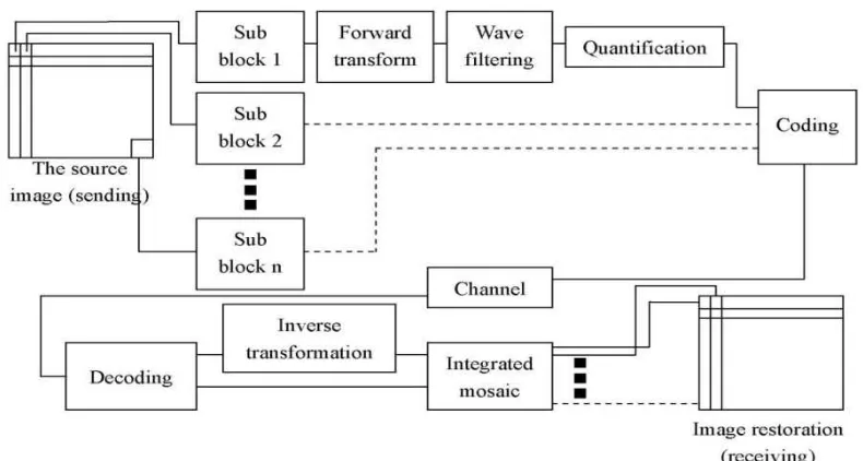
The image information compression coding is conducted according to the intrinsic statistical characteristics of the image signal and the visual characteristics of human beings. The statistical characteristics have shown that there exists strong correlation between the neighborhood pixels, the neighborhood lines and the neighborhood frames. To use certain coding method to remove such correlation can realize the data compression of the image information. This process is to reduce as much non-correlative redundant information to the image quality and it is an information-preserving compression coding. Another consideration is that the image is finally watched or judged by human eyes or the observation instrument. According to the visual physiology and physiological characteristics, certain image distortion is allowed in the restored image which undergoes the compression coding as long as such distortion is difficult to see for the general audience. This kind of compression coding is a non-preserving coding because it causes certain image information loss. The research demonstrates that the more regular the grayscale distribution of the original image is, the stronger the structural of the image contents is, the more correlative the pixels are and the more compressed the data are. The basic principle of image compression coding is indicated in Figure 1 [6].
Figure 1. Principle of image information compression
transformation to make its fixed points to be an approximation as good to the original image as possible. Then record down the corresponding parameters and use them as the fractal codes of the image for the storage and transmission. The decoding process is, firstly, to determine a group of compression affine transformations via the storage or transmission parameters to constitute an iterated function system and then seek the attractor of this system. According to the attractor theorem, such attractor is the approximation of the original image. The basic coding principle will be introduced in the form of figure and text [7].
1) Image model
Assume that (RN N , )d is the grayscale image space of NNand the grayscale valuerange is{0,1, 2,,l1}(l is normally 256, namely the quantization of8bit). In its applications, N is usually the power of 2, (i.e. 256×256, 512×512 etc). Therefore, an image I can be expressed as a matrix (Iij)N N ,Iijmeans the grayscale value of the image at( , )i j .dis a complete metric to be used in the distortion judgment and it is usually taken as root mean square (RMS):
Adopt fixed block segmentation method and segment image I into a series ofB B pixel sub-block (2D array) rulersR ii( 1, 2,,Nr), of fixed size. They won’t overlap and they
cover the entire image (Figure 2). In other words,
1
Such sub-block is called Range block (Rblock for short) and its sizes include: 4×4, 8×8, 16×16 etc. In the sub-block formed by Rblock, code them one by one according to the order of columns, namely to list the Rblocks by the following order:
11, 12, , 1n, 21, 22, , 2n, , n1, n2, , nn( / ) R R R R R R R R R nN B
Besides, imageIis divided into a series of sub-blocks{ }Nd1 i i
D with larger size and these sub-blocks can overlap and they won’t need to cover the entire image. They are called domain block (Dblock for short). In the applications, the size of Dblock corresponding to the Rblock with a size of B B is usually2B2B(i.e.8×8, 16×16 and 32×32 etc). They can be generated by moving a 2B2Bwindow from left to right and from up to down with a horizontal step-length of
h
and a vertical step-length ofv. Obviously, two neighborhood blocks have h (orv) pixels overlapped in the horizontal (or vertical) direction.In the application, the horizontal step-length is the same as the vertical step-length, namelyhv ,and the side length of Rblock is B (As indicated in Figure 3, 3D blocks are drawn here). Therefore, the number ofD blocks is
2
it is half-overlapped in the vertical (horizontal) direction [8].
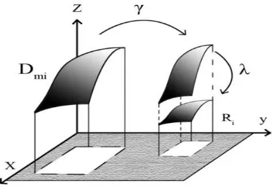
3) Search for the optimal matching block Dm i( ) of Rblock and determine the mapping parameter.
i
R, every Rblock is approximate with the size ratio resetting and brightness
transformationofDm i( ), a certainD block (Figure 4). The mapping wiusually chooses compression affine transformation and its common form is:
( ) ( ) ( )
( ) ( ( )) ( ( ))
i m i i i m i i k i m i i
w D D s t D o (2)
Figure 2. Partition scheme (R block) Figure 3. Producing D blocks
The compression affine transformationwi includes spatial contractive transformation i and grayscale modification transformationi. It can be seen from Figure 4 that the mapping i
translates from the sub-imageDm i( ) to the sub-imageRi. Then it makes its size totally overlap
the size ofRi through pixel mean value or decimation contraction. The mappingi modifies the
grayscale information ofDm i( ) to get a better approximation of the grayscale ofRi by introducing
the grayscale adjustment and the offset parameters s oi, i as Figure 5.
( 1, 2, , )
j d
D j N , every Dblock adopts 4-neighborhood pixel mean value or
decimation to get the pixel block DˆjofB B . Use S to symbolize this computation (space contraction operator), namelyS D( j)Dˆj. For example, according to the pixel expression, the 4-neighborhood pixel mean value is:
, 2 ,2 2 1,2 2 ,2 1 2 1,2 1 All such contraction sub-blocks form a “virtual codebook” and mark this codebook as , namely {Dˆj S D( j) : j1, 2,,Nd}[9].
3. Multi-Wavelet Decomposition and Reconstruction of 2D Image
The decomposition and reconstructionalgorithms of discrete multi-wavelet transform are the development of single wavelet and the difference is that the decomposition and reconstruction filters are vector filters; therefore, vector signal is required to be input into the filter. And a problem in the algorithm realization is the vectorization of the input scalar data; correspondingly, the vector data is required to be restored to scalar data in the reconstruction. This problem is usually solved through the pre-filter and the corresponding post-filter and the design of the pre-filter is related to the multi-wavelet used [10].
Assume that the corresponding 2D matrix to an image is:
0,0 0, 1
Then the steps to perform multi-wavelet transform on Image A are as follows:
(Here, N is the integer power of 2. Take r2, namely 2-level multi-wavelet transform) (1) Line pre-filtering
Firstly, form a line vector signal with every line of A according to the following way.
,2
Then, perform line pre-filtering onAiR.
,
In this formula, and pk is the matrix of 2×2, indicating the pre-filter corresponding to the wavelet used.
(2) Column pre-filtering
Form a column vector signal with every column of Baccording to the following approach.
,
Step 1: Multi-wavelet decomposition in the line direction.
Firstly, form the vector signal with every line of C according to the following means.
,
Then, perform multi-wavelet transform on every line of CiR( )n .
,In this formula, Gkis the matrix of 2×2, indicating the corresponding low-frequency filter
to multi-wavelet while Hk, a matrix of 2×2, is the corresponding high-frequency filter to the wavelet [11].
Make , , , , ,
L L H H L H
i j i j
D D D D DD D .
Step 2: Multi-wavelet decomposition in the column direction.
Similarly, form the vector signal on every column of Din the same way as the line and then perform column wavelet transform.
,
,Perform multi-wavelet transform onDiCL and H iC
D respectively [12].
, , , , , , ,
It is not difficult for us to find that due to the existence of several scaling (wavelet) functions, one sub-band after the single wavelet transform is further decomposed into 2
r sub-blocks in the multi-wavelet transform. For a 2D image, N-level wavelet decomposition will generate 2
3 1
r L sub-images. Figure 6 is the decomposed coefficient map when L2,r2. L-level multi-wavelet transform decomposes the image into 2
3 1
r L sub-blocks. The reconstruction process is the inverse process of the above steps. That is to say, performthe inverse multi-wavelet transform in the column direction. Then the line direction. And finally the post-filtering in the line direction, after that, the image reconstruction is completed [13, 14].
4. Fractal Image Compression Algorithm in Multi-Wavelet Domain
The basic idea of the fractal image compression algorithm in the multi-wavelet domain is: decompose the original image into the sub-images at different spatial frequencies through multi-wavelet transform, perform fractal coding on the high-level wavelet coefficients only by using the correlation between the wavelet coefficients at different scales and estimate the fractal code of the low-level wavelet coefficients from that of the upper-tiered wavelet coefficients. In this way, it greatly reduces the coding time and improves the compression ratio without significantly reducing the quality of the decoded image. Figure 7 is the basic procedure of multi-wavelet fractal image coding algorithm.
Figure 6. Multi-wavelet transform when L2,r2
Its specific steps are as follows:
(i) Perform 3-level wavelet decomposition on the original image and get 10 wavelet sub-images.
(ii) Take the 4*4 non-overlapping sub-blocks which are divided from the low-frequency part LL3 after the lifting wavelet transform. Perform another lifting wavelet decomposition on LL3. Take the coefficient blocks with a size of 4*4 from the same position in the decomposed 4 parts (a, b, c, d) and restore all the possible 8*8 D blocks in the original image through wavelet reconstruction algorithm. The D’, the sampled D blocks can be found in a, therefore, match all the 4*4 sub-blocks in the transformed low-frequency part a as D’ with the R blocks divided from the LL3. The range to search the optimal D’ is narrowed down to the half of the original range, thus greatly shortening the coding time. (iii) Considering the positive and negative wavelet coefficients, which is not good for the
similarity matching between the parent block and the sub-block, we extract the symbol (+ or -) of the wavelet coefficients for separate coding and we only perform fractal coding on the absolute value of the wavelet coefficients.
(iv) Perform fractal coding on the wavelet coefficients of different scales and finish the coding of the entire image.
(v) In the decoding reconstruction, estimate the fractal code of scale 1 based on that of scale 2. And the estimation formula is:
1 2
Here, s1and s2are the scalar coefficients of scales 1 and 2 in the wavelet coefficient matrix respectively,r1avrand r2avrare the grayscale offset coefficients of scales 1 and 2 respectively and 5. Reconstruct the wavelet coefficients of different scales with the fractal codes of the scales. Then add the symbol of wavelet coefficient. Integrate the decoded low-frequency part with the high-low-frequency part. Perform inverse wavelet transform, the image decoding reconstruction is completed.
5. Experiment Simulation and Analysis
According to the algorithm based on wavelet fractal image compression coding, experiment on the images of Lena and pper and compare with the fractal image compression coding. The experiment test platform is CPU: Intel(R) Core(TM)2CPU, 1.35GHZ, RAM:2.0G, the operating system is: Windows 7 and the experimental environment is: Matlab2012a. The test performance parameters include compression ratio, peak signal to noise ratio (PSNR) and coding time (s).
(a) Decoding image of multiwavelet-FIC (b) Decoding image of FIC
(c) Decoding image of multiwavelet-FIC (d) Decoding image of FIC
Figure 8. Comparison between multiwavelet-FIC and FIC
Table 1. Test Results Comparison Between Multiwavelet-FIC and FIC
FIC Multiwavelet-FIC
Time(S) Compression ratio PSNR(dB) Time(S) Compression ratio PSNR(dB)
Pears 27.358 13.556 29.53 19.861 12.209 28.87
Peppers 41.476 11.268 31.86 33.668 10.241 30.92
6. Conclusion
The image characteristics are closely related to the compression effect. In order to better match the image characteristics with compression algorithm, this paper has proposed a new multi-wavelet fractal image compression algorithm. Through the experiment performance simulation and comparison experiment, it can be seen that compared with FIC, this new algorithm has excellent effects and it effectively improves the compression performance, shortens the time of the matching search and increases the coding speed.
References
[1] Ming-Sheng Wu. Genetic Algorithm Based on Discrete Wavelet Transformation for Fractal Image Compression. Journal of Visual Communication and Image Representation. 2014; 25(8): 1835-1841. [2] Roberto de Quadros Gomes, Vladimir Guerreiro, Rodrigo da Rosa Righi, Luiz Gonzaga da Silveira Jr,
Jinyoung Yang. Analyzing Performance of the Parallel-based Fractal Image Compression Problem on Multicore Systems. AASRI Procedia. 2013; 5(2): 140-146.
[3] Yi Zhang, Xingyuan Wang. Fractal Compression Coding Based on Wavelet Transform with Diamond Search. Nonlinear Analysis: Real World Applications. 2012; 13(1): 106-112.
[4] Kamel Belloulata, Amina Belalia, Shiping Zhu. Object-based Stereo Video Compression using Fractals and Shape-Adaptive DCT. AEU-International Journal of Electronics and Communications. 2014; 68(7): 687-697.
[6] Arikatla Hazarathaiah, B Prabhakara Rao. Medical Image Compression using Lifting based New Wavelet Transforms. International Journal of Electrical and Computer Engineering. 2014; 4(5): 741-750.
[7] Qi-gao Feng, Hao-yu Zhou. Research of Image Compression Based on Quantum BP Network. TELKOMNIKA Indonesian Journal of Electrical Engineering. 2014; 12(1): 197-205.
[8] Yang Ran, Zuo Yanjun, Lei Wanjun. Researching of Image Compression Based on Quantum BP Network. TELKOMNIKA Indonesian Journal of Electrical Engineering. 2013; 11(11): 6889-6896. [9] Fatemeh Daraee, Saeed Mozaffari. Watermarking in Binary Document Images using Fractal Codes.
Pattern Recognition Letters. 2014; 35(1): 120-129.
[10] S Fujimoto, A Rinoshika. Wavelet Multi-resolution Analysis on Turbulent Wakes of Asymmetric Bluff Body. International Journal of Mechanical Sciences. 2014; 92(3): 121-132.
[11] B Andò, S Baglio, A Pistorio. A Low Cost Multi-sensor Strategy for Early Warning in Structural Monitoring Exploiting A Wavelet Multiresolution Paradigm. Procedia Engineering. 2014; 87(5): 1282-1285.
[12] Wu Xiang, Qian Jian-Sheng. Combine Multipredictor of Gas Concentration Prediction Based on Wavelet Transforms. TELKOMNIKA Indonesian Journal of Electrical Engineering. 2014; 12(10): 7361-7368.
[13] Zhuang Wen Wu, Liangrong Zhu. Car Information Bus Image Restoration Using Multiwavelet Transform Algorithm. TELKOMNIKA Indonesian Journal of Electrical Engineering. 2013; 11(10): 6158-6165.