ISSN: 1693-6930
accredited by DGHE (DIKTI), Decree No: 51/Dikti/Kep/2010 741
Finite Element Method Using PDETOOL of Matlab for
Hybrid Stepper Motor Design
E.V.C. Sekhara Rao*1, P.V.N. Prasad2
1
Chaitanya Bharathi Institute of Technology (CBIT), Hyderabad, India
2
University College of Engineering (UCE), Hyderabad, India
e-mail: [email protected]*, [email protected]
Abstrak
Makalah ini menyajikan delapan topologi rancangan motor langkah magnet permanent hibrida khususnya tentang analisis unjuk kerja rangkaian magnetik berdasarkan metode elemen hingga yang terdapat dalam PDETOOL dari perangkat lunak Matlab. Topologi dirancang sesuai jumlah gigi stator dan panjang celah udara. Analisis ini digunakan untuk mengetahui distribusi gaya gerak magnetik (mmf) yang disebabkan oleh magnet permanen dan kumparan penguatan. Analisis ini akan membantu pemilihan rancangan terbaik berdasarkan distribusi mmf yang lebih baik.
Kata kunci: FEM, PDE toolbox, PMH motor stepper
Abstract
This paper presents eight topologies design of permanent magnet hybrid (PMH) stepper motor for it’s magnetic circuit performance analysis using finite element method by PDETOOL of Matlab. The topologies are designed according to the number of stator teeth and length of airgap. This analysis is used to know mmf distribution due to permanent magnet and by exitation coil.This analysis helps to chose best design topology for better mmf distribution.
Keywords: FEM, PDE toolbox, PMH stepper motor
1. Introduction
Stepper motor is a special motor used for discrete torque without any interface. Many techniquis like direct torque control (DTC) may raplace aplications of induction motor or servomotor with permanent maget synchronous motor (PMSM) [1] but could not replace stepper motor.It is classified into three major types as permanent magnet stepper motor, Variable reluctance stepper motor and Permanent magnet hybrid (PMH) stepper motor [2]. Among all PMH motor is widely used in many applications such as solar array tracking system in satellites, robotics and CNC machines due to its micro-stepping quality with high torque capacities [3]. But its magnetic circuit analysis is complicated due to the presence of permanent magnet and double slotting which is not discussed in detail in [4]. Its magnetic circuit is explained earlier with equivalent circuit model with linear assumsions in [2], [3].
Airgap variation effect on mmf distribution is explained in [4] using equivalent circuit model without considering exact topology of motor. This method is unable to give detail explanation for different topologies mmf distribution.
But getting operating point mmf with permanent magnet is complicated. Finite element model is used for getting accurate operating point of permanent magnet using tooth layer unit [5].But mmf distribution was not explained in detail for different topologies.
Fem analysis is carried for mmf distribution with different tooth geometries in [6] but variation of materials and current densities are not discussed in detail and analysis is carried using commercial software.
PMH stepper motor then required boundary conditions are applied then solution is obtained through FEM relations for eight topologies.
Topologies are considered with variation in airgap, stator number of teeth. Two core materials are considered for stator and rotor (Iron (99.8%), Iron (99.95%). Two current densities are considered for analysis (0.5 A, 1 A).
2. Research Method
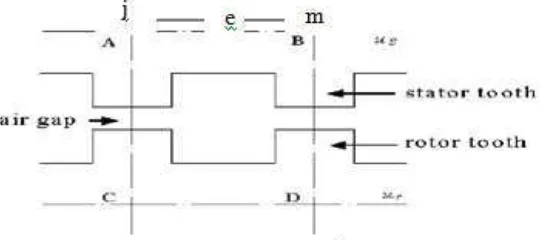
Tooth layer unit (TLU) [3] is a rectangle area that has a tooth pitch width and two parallel lines behind the teeth of stator and rotor. The area is shown in Figure 1. The factors of the nonlinear material and the non-uniform distribution of magnetic field in the teeth of stator and rotor are taken full consideration in this computation model. There are two basic assumed conditions in the computation model of TLU.
(i) The lines AB and CD of the TLU in Figure 1 are thought as iso-potential lines.
(ii) The magnetic edge effect of stator pole is ignored, which is assumed that the distribution of the magnetic field for every tooth pitch width is the same.
Figure 1 shows stator and rotor tooth geometry for one tooth pitch. In Figure 1, us, and
ur are scalar quantities of the iso-potential lines AB and CD. The magnetic potential difference F
is given by
F = Uୱ− U୰ (1)
Figure 1. The tooth layer unit
If Φ (α) is assumed as the flux in a tooth pitch width and per axial unit length of iron core, α is the relative position angle of stator and rotor. The specific magnetic conductance G of TLU is then given by
G =Φሺሻ
(2)
where φ is the scalar quantity, µ is the magnetic permeability and λ is the tooth pitch. For a certain position angle α and a magnetic potential difference F, the distribution of the magnetic field of TLU can be calculated by the 2D finite element analysis. The flux per axial length of TLU is given in (4).
, = ∑ (4)
Here the nodes j and m are on the border AB as shown in Figure 1. is the length of unit e from node j to m and Be is the flux density. The specific magnetic conductance G will be used in
the calculation of the whole nonlinear network equations of the motor.
Though TLU, the key calculation model of the method is simple in drawing, its calculation model contains some approximate factors due to the basic assumed conditions. It is the main issue to be studied in this paper whether the assumed conditions are of engineering rationality or whether the assumed conditions are in agreement with the practical situations and whether the errors from the assumed conditions can be ignored from the point view of engineering. The two basic assumed conditions (i) and (ii) mentioned are analyzed below. A practical PMH stepper motor was chosen to analyze the rationality. It has 4 poles in the stator and 6 sections in the rotor with disc of NdFeB magnet axially magnetized. The main structure parameters of the motor are shown in Table I.
As the motor is symmetrical, pair of poles of the motor has been chosen as the magnetic numerical calculation area, the magnetic field contains the nonlinear material, iron core, and the current area. The surface arc effect of the iron core and the pole edge effect of the stator are considered in the calculation model, by which the magnetic potential values and their differences on the lines behind the teeth could be found out and the engineering rationality of the assumed conditions could be verified. There is only axial current in Figure 2 and the magnetic potential vector Az suits Poisson's equation [4], [5] as
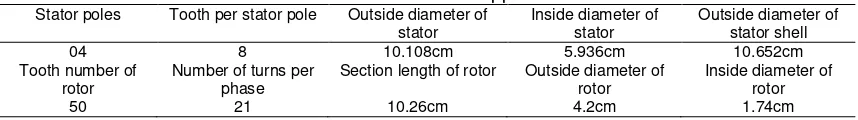
Table 1. Data of PMH stepper motor
Stator poles Tooth per stator pole Outside diameter of
stator
Section length of rotor Outside diameter of
rotor
(((R1)+(R3))(C3+SQ1+SQ2+SQ3+SQ7+SQ8+SQ9+SQ25+SQ26+SQ27+SQ28+SQ29+SQ30))+(C2-SQ4
-SQ5-SQ6-SQ10-SQ11-SQ12-SQ13-SQ14-SQ15-SQ16-SQ17-SQ18-SQ19-SQ21-SQ20-SQ22-SQ23-SQ24
-SQ37-SQ38-SQ39-SQ40-SQ41)+((R2+R4)-C4)+R5+SQ42+C6+C5+C1)*SQ43')
where R1, R2 are designed for stator pole 1 and R5 is designed as current coil on pole1. R4, R5
are designed for stator pole 2 and SQ42 is designed as current coil on pole2. SQ1, SQ2, SQ3,
SQ7, SQ8, SQ9, SQ25, SQ26, SQ27 are designed as teeth on stator poles. SQ4-SQ5-SQ6-SQ10
-SQ11-SQ12-SQ13-SQ14-SQ15-SQ16-SQ17-SQ18-SQ19-SQ21-SQ20-SQ22-SQ23-SQ24-SQ37-SQ38-SQ39
-SQ40-SQ41 are created equally to provide 23 rotor teeth. SQ43 is to provide the required
boundary. R6 is the extra teeth on stator for smooth performance of the motor. From the mentioned set formula (8) the geometry is obtained as shown in Figure 2 for uniform airgap with extra teeth on stator and Figure 3 for uniform airgap without extra teeth on stator.
Figure 2. Stator rotor geometry of PMH stepper motor for uniform narrow air-gap (0.137 mm) with extra teeth on stator
Figure 3. Stator rotor geometry of PMH stepper motor for uniform narrow air-gap (0.137 mm) without extra teeth on stator.
3.2. Motor Boundary Conditions
For getting magnetic potential at the border Dirichlet boundary condition is considered as (1, 0) and Neumann condition specified as (0, 0).
Figure 4. Stator rotor geometry of PMH stepper motor for uniform narrow air-gap (0.137 mm) with extra teeth on stator after boundary conditions implemented
Figure 5. Stator rotor geometry of PMH stepper motor for uniform narrow air-gap (0.137 mm) without extra teeth on stator after boundary conditions implemented
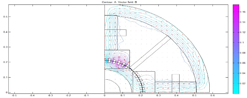
Figure 6. PDE solution for Iron (99.8%) core material with NdFeB permanent magnet with extra teeth on stator without excitation
3.3. PDE Model for Solution
Permanent magnet portion permeability is also calculated using (19) and current density is calculated [3]. Two types of permanent magnetic materials are used in this investigation like NdFeB, Se2Co17.
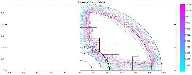
Figure 7. PDE solution for Iron (99.8%) core material with NdFeB permanent magnet with extra teeth on stator with excitation for current density of 17056A/m2
Figure 8. PDE solution for Iron (99.8%) core material with NdFeB permanent magnet without extra teeth on stator without excitation
Current density is considered zero and permeability as one for airgap and current coil to investigate permanent magnet operating point. Current density is considered for current coil to investigate total mmf under exciting condition.
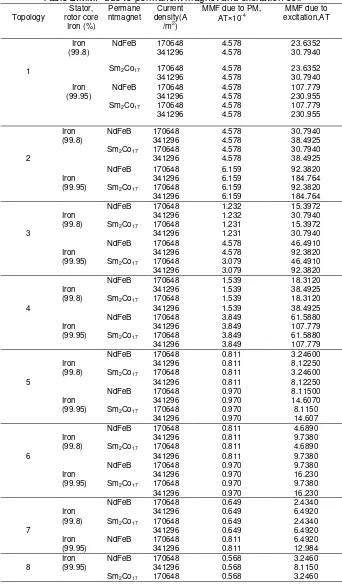
Table 2.MMF due to permanent magnet and excitation coil
Topology
NdFeB 170648 4.578 23.6352
341296 4.578 30.7940
Sm2Co17 170648 4.578 23.6352
341296 4.578 30.7940
Iron (99.95)
NdFeB 170648 4.578 107.779
341296 4.578 230.955
NdFeB 170648 4.578 30.7940
341296 4.578 38.4925
NdFeB 170648 1.232 15.3972
341296 1.232 30.7940
Sm2Co17 170648 1.231 15.3972
341296 1.231 30.7940
Iron (99.95)
NdFeB 170648 4.578 46.4910
341296 4.578 92.3820
NdFeB 170648 0.811 3.24600
341296 0.811 8,12250
Sm2Co17 170648 0.811 3.24600
341296 0.811 8,12250
Iron (99.95)
NdFeB 170648 0.970 8.11500
Considering all these conditions PDE solution is obtained as shown in Figure 5, Figure 6, Figure 7, and Figure 8. Figure 5 and Figure 7 are magnetic potential diagrams for PMH stepper motor under permanent magnet excitation for with and without extra teeth on stator respectively. Figure 6 and Figure 8 are magnetic potential diagrams for PMH stepper motor under permanent magnet and current coil excitations for with and without extra teeth on stator respectively.
PDE toolbox of Matlab for FEM analysis of PMH stepper motor is used to investigate mmf due to permanent magnet for different topologies which is difficult to investigate by mathematical model. Different topologies considered are 1) Uniform air-gap (0.137 mm) with extra teeth on stator 2) Uniform air-gap (0.137 mm) without extra teeth on stator 3) Non-uniform air-gap (0.137 mm) with extra teeth on stator 4) Non-uniform air-gap (0.137 mm) without extra teeth on stator 5) Uniform air-gap (0.93 mm) with extra teeth on stator 6) Uniform air-gap (0.93 mm) without extra teeth on stator 7) Non-uniform air-gap (0.93 mm) with extra teeth on stator 8) Non-uniform air-gap (0.93 mm) without extra teeth on stator. The details of all the eight topologies are shown in Table 2.
4. Conclusion
MMF distribution of pmh stepper motor is found uniform with uniform airgap topologies (topologies 1,2 and 5,6). More mmf interaction between stator and rotor is found for low airgap topologies (0.137 mm).Leakage flux is minimized using extra teeth on stator (topologies Performance PMSM Drives. TELKOMNIKA Indonasian Journal of Electrical Engineering. 2008; 6(3): 155-166.
[2] H. Chai. A Mathematical Model for Single-Stack Step Motors. IEEE Transactions on Power
Apparatus and Systems. 1975; 94(5).
[3] KR Rajagopal, M. Krishnaswammy, Bhim Singh and B. P. Singh. An Improved High- Resolution Hybrid Stepper Motor for Solar-Array Drive of Indian Remote- Sensing Satellite. IEEE Transactions on Industry Applications. 1997; 33(4).
[4] KR Rajagopal, Bhim Singh and B. P. Singh. Effects of Non-Uniform Airgap and Hysteresis on the Performance of Hybrid Stepper Motor. IEEE transactions on Industry Applications. 1998; 34(3). [5] Dou Yiping. The Engineering Rationality of a Hybrid Stepping Motor Calculation Model. Proceedings
of the CSEE. 1999; 19(5): 35-38.
[6] Praveen RP, Ravichandran MH, VT Sadasivan Achari, Jagathy Raj VP, G Madhu and R Bindu. Design and Finite Element Analysis of Hybrid Stepper Motor for Spacecraft Applications’, IEEE transactions on Magnetics. 2009; 45(4).
[7] Khairudin M. Dynamic Modelling of a Flexible Link Manipulator Robot Using AMM. TELKOMNIKA Indonasian Journal of Electrical Engineering. 2008; 6(3): 185-190.
[8] Juha Pyrh¨onen, Tapani Jokinen, Val´eria Hrabovcov´a. Design of Rotating Electrical Machines. John Wiley & Sons, Ltd. 2008.
[9] Jacek F. Gieras, Mitchell Wing. Permanent Magnet Motor Technology Design and Applications. Marcel Dckker Inc. New York, USA.
[10] Golub, Gene H., and Charles F. Van Loan, Matrix Computations. 2nd edition. Johns Hopkins University Press, Baltimore. MD. 1989.