ISSN: 1693-6930
accredited by DGHE (DIKTI), Decree No: 51/Dikti/Kep/2010 515
Development of Tubular Linear Permanent Magnet
Synchronous Motor Used in Oil-well Field
Yanliang Xu, Xiquan Liu
School of Electrical Engineering, Shandong University No.17923 Jingshi Road, Jinan City, P.R.China, 250061 Ph: 0086-0531-81696170, e-mail: [email protected]
Abstrak
Motor sinkron permanen magnet motor linear tubular (TLPMSM) dikembangkan untuk mengganti sistem pompa minyak-baik baru bernama sebagai linear motor-driven. Salah satunya untuk menggantikan sistem pompa normal beam balanced terutama untuk mengeliminasi kemungkinan kerusakan tiang baja. Strukturnya ditentukan berdasarkan kebutuhan pengemudian nyata dan hasil analisis bersesuaian yang diberikan. Pada penelitian ini sebuah purwarupa TLPMSM kecil berdiameter stator luar 140mm, panjang stator efektif 864mm dirancang dan diproduksi untuk memverifikasi analisis teoritis dan menyelidiki kinerja, dan membuat persiapan untuk purwarupa praktis besar yang lebih besar di masa depan.
Kata kunci: analisis FEM, ekperimen, oil-well field
Abstract
The tubular linear permanent magnet synchronous motor (TLPMSM) is developed to constitute a new oil-well pump system named as linear motor-driven one replacing the normal beam balanced pump system mainly in order to eliminate the damageable steel pole. Its structure is determined based on the real drive demand and the corresponding analysis results are given. At last a small prototyped TLPMSM with stator outer diameter of 140mm, effective stator length of 864mm is designed and manufactured to verify the theoretical analysis and investigate the performance, and make preparation for the large practicable prototype in the future.
Keywords: FEM Analysis, expriment, oil-well field, tubular linear PMSM
1. Introduction
The normal beam-balanced pump system shown in Figure 1 which is used widely nowadays in oil field has many drawbacks such as low life-span of steel pole, low system efficiency, high occupied ground space and so on.
So a new oil-well pump system named as linear motor-driven one shown in Figure 2 is presented to replace the normal system mainly to eliminate the damageable steel pole, as well as to obtain other performance improvement. The linear motor which can be adopted in the new oil-well pump system is classified to planar one and tubular one according to its structure configuration, or induction one and PM one according to its field excitation mode. Considering the requirement of high force-to-volume and efficiency, thin and long structure, and good adaptability in bad surroundings with high pressure, high ambient temperature, and abundance of moisture and sands, tubular linear permanent magnet synchronous motor (TLPMSM) is the most feasible choice.
The real TLPMSM used in the liner motor-driven pump system requires maximum force production of about 40000N with outer stator diameter less than 140mm, which may lead to a very long mover of about 10m in consideration of its run range and other accessories. Thanks for the inherent advantage of all kinds of linear motors that they can enlarge their force capability easily just by extending their effective lengths. So, in this paper, only a small prototyped TLPMSM is analyzed, designed and manufactured to make preparation for the large practicable prototype in the future.
2. Structure and Analysis of the TLPMSM
In order to constitute the practicable prototype in the future easily according to the small prototyped TLPMSM, the latter has the same three-phase power supply with rated voltage of 550V, the same rated running speed of 0.7m/s, and the same stator outer diameter as the former. For the same reason, the initially developed TLPMSM don’t mind its rated and maximum force production.
2.1 Whole Structure with Dynamic Seal
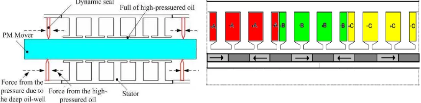
The TLPMSM is used to drive directly the oil-well pump situated underground with the maximum depth of 3km where there exists a pressure of about 30 Mpas, which exerts a great challenge to the motor’s seal to guard the winding insulation, so a dynamic seal is adopted, as shown in Figure 3. High-pressured oil is filled into the TLPMSM, through which a high force occurs to keep balance with the ambient pressure through the dynamic seal. As a result, the winding insulation is easy to realize.
2.2 Stator Winding, Stator Core and Mover Magnet Configuration
Three-phase TLPMSM can consist of many identical motor modules, every of which may be 3-slot/2-pole, 3-slot/1-pole, 6-slot/1-pole, 9-slot/10-pole, or 12-slot/10-pole. In order to obtain a sinusoidal back-EMF waveform, a smooth force production, a high winding fundamental coefficient and a easy manufacture, 9-slot/10-pole winding configuration as shown in Figure 4 is chosen and the prototyped TLPMSM is composed of four motor modules and then employs 36 stator slot and 40 effective poles. The pole pitch is determined as 21.6mm, which means inverter frequency output of 16.2Hz in order to reach the demand speed of 0.7m/s.
Figure 3. The dynamic seal adopted in the TLPMSM
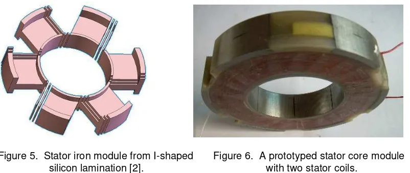
In order to reduce the iron loss, the stator core is fabricated from I-shaped silicon iron lamination shown in Figure 5, and Figure 6 presents a prototyped stator core module with two stator coils.
Figure 5. Stator iron module from I-shaped Figure 6. A prototyped stator core module silicon lamination [2]. with two stator coils.
There are three kinds of mover magnet configurations which can be used in the TLPMSM named as axial magnetized configuration, radial magnetized one and Halbach magnetized one respectively. The first one is adopted as shown in Figure 4 in the prototyped TLPMSM mainly taking its easy manufacture into consideration, and then the suitable magnet axial length of 11.6mm is chosen to obtain a high fundamental no-load flux density. The NdFeB magnet used in the prototyped features remnant flux density of 1.29T and intrinsic coercitive force of 2000kA/m, with maximum endurable working temperature of 180°C.
3. Parameter Calculation
Parameters of TLPMSM mainly refer to leakage reactance which consists of slot leakage reactance, harmonic one and teeth top one. The second and the third one are similar to that of the rotating electric machines, so only slot leakage reactance is concerned here.
Figure 7 shows the stator slot structure of TLPMSM. From Figure 7 It is easy to get the slot leakage reactance per phase.
a
4. Stator Magnetomotive Force Analysis
Figure 7. Slot structure of TLPMSM Figure 8. MMF waveform of phase A when fed by direct current ia
The MMFs of phase B and C can also be obtained similar to that of phase A, then the armature resultant MMF of the TLPMSM is easily achieved and its n/5 order component can be expressed as
when n=5, Fn/5 means the fundamental component F1.
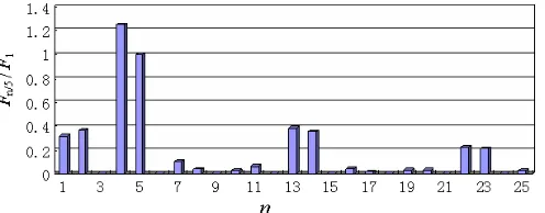
Figure 9 gives the variation of Fn/5/F1 with component order n which shows that the TLPMSM with 9 slot/10 pole is full of fractional-order MMF harmonics and the magnitude of 4/5 order harmonic is higher than that of fundamental one.
Figure 9. Variation of Fn/5/F1 with n
5. Unilateral Magnetic Force Calculation
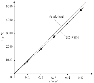
Theoretically, TLPMSM features zero net attractive force between stator and mover, but owing to mover eccentricity resulting from the linear bearing clearance and the flexibility of mover especially in the thin and long TLPMSM such as the presented in this paper, unilateral magnetic force comes into being and may result in a large friction drag by which the motor force may reduce greatly. Considering the larger air-gap and larger thickness of magnet of the presented TLPMSM in this paper which results in a very small armature reaction on the air-gap magnetic field, the unilateral magnetic force is calculated in this paper only when in no-load.
the prototyped TLPMSM will generate a very high unilateral magnetic force when with a larger eccentricity, as a result a high friction may occur between stator and mover.
e
And where, R1 and R2 are outer and inner radiuses of magnet respectively, δ is air-gap length, µr is relative recoil permeability of magnet, L is stator length, and Kδ is Carter coefficient which is used to take the slot opening into consideration and Bδ is air-gap flux density when no
eccentricity.
Figure 10. 3D-FEM mesh Figure 11. Unilateral magnetic force calculation
Table 1. Structure Specification of the Prototyped TLPMSM
Parameter Value
Outer diameter of stator 140mm
Stator core effective length 864mm
Mover length 4000mm
Pole pitch 21.6mm
Effective air-gap length 2.3mm
Outer diameter of magnet 30.7mm
Inner diameter of magnet 22.5mm
Figure 12. The prototyped TLPMSM
6. Prototyped TLPMSM and Its 2D-FEM Analysis, Experiment
developed PLPMSM is summed in Table I and the prototyped TLPMSM is shown in Figure 12.
6.1 2-D Fem Analysis
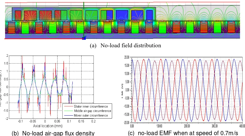
In order to increase the mesh density as well as to quicken the analysis when using 2-D Fem, only one module motor is specified to simulate the whole prototyped TLPMSM. Figure 13 gives its no-load simulation,from, which, it can be seen that the prototyped TLPMSM employs a excellent phase EMF waveform due to the adoption of 9-slot/10-pole structure and rational pole pitch.
(a) No-load field distribution
(b) No-load air-gap flux density (c) no-load EMF when at speed of 0.7m/s
Figure 13 2d-Fem No-load simulation for the developed TLPMSM
(a) Speed variation (b) Megnetic force variation
(c) Phase current variation
The starting simulation is also executed when giving terminal speed of 0.7m/s, supplied by load force of 900N and damping of 285.7 N/(m/s), and the results are shown in Figure 14, from which, it can be seen that the prototyped TLPMSM has a good starting performance and has a smooth force and speed output.
6.2 Experiment
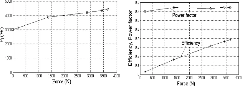
The no-load back phase voltage waveform is given in Figure15, which presents a good sinusoidal one and results definitely in a smooth running. When the inverter is supplied by 340V, and set frequency output of 11Hz which means a mover run speed of 0.475 m/s, the variation of the input power of inverter, the TPMSM aystem efficiency, and the power factor as a function of the output force are shown in Figure 16, from which, it can be seen that there exist an increment of inverter input power from 3030W to 4440W along with the variation of output force from zero to 3660N, and there are low efficiency and high and nearly invariable power factor.
Figure 15. No-load phase back voltage waveform of prototyped TLPMSM
Figure 16. Variation of the inverter input power, efficiency and power factor of TLPMSM with the output force when the inverter with 430V input and 11Hz output
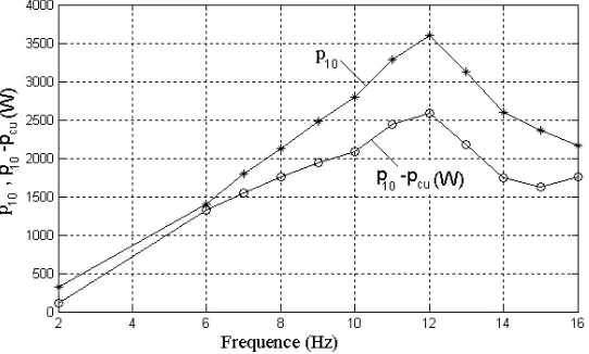
Figure 17. Variation of p10 and p10-pcu with the inverter ouput frequence when no load
As shown in Figure 17, the prototyped TLPMSM has maximum force of 3660N when the inverter being supplied voltage of 430V and the motor running at 0.475m/s. If the TLPMSM can run without so high mechanical loss, the prototyped TLPMSM will generate a much higher maximum force and running efficiency, which satisfies the real performance demand to much extent. Considering the good work of the dynamic seal equipment additionally, the next work is to design and manufacture a real prototyped TLPMSM which can be used in the real oil well with rated and maximum force ouput of 25000N and 40000N respectively just by enlarging the sum of motor modules based on the small prototyped TLPMSM.
7. Conclusion
For the application in linear motor-driven pump system, the TLPMSM is analyzed, and a small prototyped TLPMSM is designed, manufactured and tested for the preparation of the future practicable one. By adoption of dynamic seal, 9-slot/10-pole stator winding, module core from I-shaped silicon laminations, and axial-magnetized magnet, the small prototype with effective stator length of 864mm, and outer stator diameter of 140mm, features a smooth force production with high maximum magnitude, and high efficiency if some measures are taken to reduce its mechanical loss in the future. Based on the mentioned work, a real prototyped TLPMSM which will be used in oil-field, can easily realized in future.
Acknowledgement
The authors would like to thank the Shandong Natural Science Foundation of China (2009ZRB01067) which was supported this research.
References
[1] Jiabin Wang, David Howe. Design Optimization of Radially Magnetized Iron-cored, Tubular Permanent-magnet Machines and Systems. IEEE Transactions. On Magnetics. 2004; 40(5): 3262-3277.
[2] Jiabin Wang, David Howe, Influence of Soft Magnetic Materials on the Design and Performance of Tubular Permanent Magnet Machines. IEEE Transactions on Magnetics. 2005; 41(10): 4057-4059. [3] Nicola Bianchi, Silverio Bolognani and etc. Tubular Linear Permanent Magnet Motors: an Overall
Comparison. IEEE Transactions on Industry Applications. 2003; 39(2): 466-475.