DOI: 10.12928/TELKOMNIKA.v12i2.2022 357
Multi-focus Image Fusion with Sparse Feature Based
Pulse Coupled Neural Network
Yongxin Zhang1,2, Li Chen*1, Zhihua Zhao1, Jian Jia3 1
School of Information Science and Technology,Northwest University, Xi’an 710127, Shaanxi,China
2 Luoyang Normal University, Luoyang 471022, He’nan, China
3
Department of Mathematics, Northwest University, Xi’an 710127, Shaanxi, China *Corresponding author, e-mail: [email protected]
Abstract
In order to better extract the focused regions and effectively improve the quality of the fused image, a novel multi-focus image fusion scheme withsparse feature basedpulse coupled neural network (PCNN) is proposed. The registered source images are decomposed into principal matrices and sparse matrices by robust principal component analysis (RPCA).The salient features of the sparse matrices construct the sparse feature space of the source images. The sparse features are used to motivate the PCNN neurons. The focused regions of the source images are detected by the output of the PCNN and integrated to construct the final fused image. Experimental results showthat the proposed scheme works better in extracting the focused regions and improving the fusion quality compared to the other existing fusion methods in both spatial and transform domain.
Keywords: image fusion, robust principal component analysis, pulse-coupled neural network, sparse feature, firing times
1. Introduction
Multi-focus image fusion is a process that different images with different settings are integrated to produce a new image contains all relevant objects in focus,which is very useful for human or machine perception [1].In general, image fusionmethods can be categorized into two groups: spatial domain fusion and transform domain fusion [2]. The spatial domain fusion methods are easy to implement and have low computational complexity,but the spatial domain methods may produce blocking artifacts and compromise the quality of the final fused image. Different from the spatial domain fusion, the transform domain fusion methods can get improved contrast, better signal-to-noise ratio and better fusion quality [3],but the transform domain fusion methods are time/space-consuming to implement.
of RPCA in the multi-focus image fusion and achieved a consistently good fusion result, but their method requires longer computational time. Different from Wan’s method,the main contribution of this paper is that the sparse features of the source images are used to motivate thePCNN neurons for image fusion. The sparse matrices of the source images are obtained by using RPCA decomposition. The sparse feature computed from the sparse matrices are used to motivate the PCNN neurons. The focused regions are detected by comparing the firing times of the PCNN neurons. The proposed method can efficiently extract the focused regions details from the source images and improve the visual quality of the fused image.
The rest of the paper is organized as follows. In section 2, the basic idea of RPCA and PCNN will be briefly described, followed by the new method with RPCA and PCNN for image fusion in section 3. In section 4, extensive simulations are performed to evaluate the performance of the proposed method. In addition, several experimental results are presented and discussed. Finally, concluding remarks are drawn in section 5.
2. Related Work
2.1. Robust Principal Component Analyisis
RPCA is an effective way to recover both low-rank and sparse components exactly from high dimensional data by solving the principal component pursuit [13]. In which, an input data
matrix M N
D¡ issubject to low-rank property. In order to recover the low-rank structure of D,
D can be decomposed as:
, ( ) min( , )
D A E rank A = M N (1)
where matrix A is a principal matrix, and Eis a sparse matrix. It is obvious that this problem is difficult to solve. Recently, Wright et al [16] have demonstrated that when the sparse matrix E
is sufficiently sparse (relative to the rank of A), one can accurately recover the principal matrix
A from D by solving the following convex optimization problem [17]:
* 1
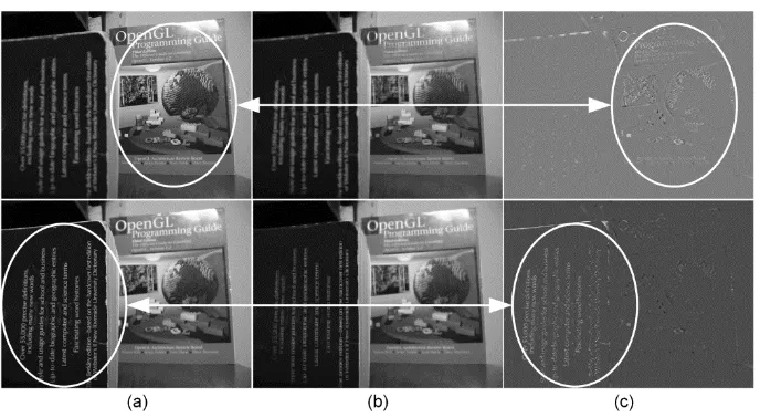
Figure 1. Decomposition of multi-focus images ‘Book’ using RPCA: (a) Source images D;(b) Principal matrix A; (c) Sparse matrix E
2.2. Pulse Coupled Neural Network
PCNN is a feedback network and belongs to the third generation artificial neural network. In image processing, PCNN is a single layered, two-dimensional, laterally connected with image pixels each other. Each PCNN neuron consists of three parts: the receptive field, modulation field and pulse generator. The PCNN neuron’s specific structure is shown in Figure 2. The neuron can be described as[7]:
( ) ( 1) ( 1) dislocation in a symmetric neighborhood around the one pixel. n denotes the current iteration and Sij denotes the input stimulus such as the normalized gray level of image pixels. F , L
and are the decay constants of the PCNN neuron. VF, VL and V are the magnitude scaling terms. The constant is the linking strength.Fij is the primary input from the neurons receptive fields. Lij is the secondary input of lateral connections with neighboring neurons. The
inter-connections Mand W are the constant synaptic weight matrices for Fij and Lij, respectively.
is a dynamic neuron threshold. The neuron will generate pulse when Uij( )n ij( )n . This pulse is also called one firing time.The sum of Yij in n iteration is called firing times, to represent image information, which isdefined as [7]:
( 1) ( )
ij ij ij
Figure 2. A PCNN neuron model
The advantage of PCNN in image fusion lies in its global coupling and pulse synchronization of neurons.In this paper, the focused regions are detected by comparingthe firing times of the PCNNneurons.
3. Multi-focus Image Fusion with Sparse Feature Based PCNN 3.1. Fusion Algorithm
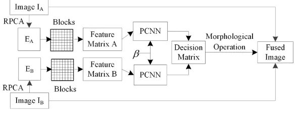
In this subsection, a novel algorithmof multi-focus image fusionis proposed and the fusion framework is depicted in Figure 3. For simplicity, this paper assumes that there are only two source images, namely IA and IB, respectively. The rationale behind the proposed algorithm applies to the fusion of more than two multi-focus images. The source images are assumed to pre-registered and the image registration is not included in the framework. The fusion algorithm consists of the following 4 steps:
Figure 3. Block diagram of proposed multi-focus image fusion framework
Step 1: Construct data matrixD. The source images {IA,IB},IA,IB¡ M N is converted
into column vectors 1
,
c c MN
A B
I I ¡ , respectively.The data matrix D is defined as:
[ c c]
A B
D I I (5)
Step 2: Perform RPCA decomposition on Dto obtain aprincipal matrix A¡ MN2 and a sparse matrix E¡ MN2, respectively. The sparse matrix E¡ MN2 is computed through inexact augmented Lagrange multipliers algorithm (IALM) of RPCA [13], which is a fast version of implementation for recovering low-rank matrices. The sparse matrixE¡ MN2 is converted
M N
Step 3:Construct PCNN model with the sparse feature computed from the sparse matrices EA,EB¡ M N , respectively.
Step 4:According to the fusion rules, the focused regions of the source images are integrated to obtain the fused image.
3.2. Fusion Rules
There are two key issues [19] for the fusion rules. One is how to measure the activity level of the focused regions, which recognizes the sharpness of the source images.Figure 1 shows that the salient features of sparse matrix Eagree well with the local features of thefocused objects in the source images. The salient features represent the sparse features of the source images. Moreover, the advantage of PCNN in image fusion is global coupling and pulse synchronization of neurons. Thus, we use the firing times of the PCNN neurons to measure the activity level. The PCNN neurons are motivated by the sparse feature computed from the sparse maitrices. respectively. The EOL of each block is used as the sparse feature of the source images, which can be calculated as [18]:
E , respectively. The EOL of each
block of the sparse matrices constructs the feature maps FAand FB, respectively. FAandFB
are input to PCNN to motivate the neurons to generate pulse with Equation (3), and the firing times of the neurons are calculated with Equation (4).
The other is how to integrate the focused pixels or regions of the source images into the counterparts of the fused image.The firing times of the corresponding blocks are compared to determine which block is in focus.A decision matrix H¡ M N is constructed for recording the comparison results according to the selection rule as follows:
1 ( ) ( )
However, judging by the firing times of the PCNNneurons alone is not sufficient to detect all the focused blocks. There are thin protrusions, narrow breaks, thin gulfs and small holes inH . To overcome these disadvantages, morphological operations [20] are performed on
4. Experimental Results
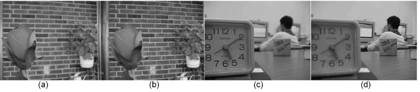
In order to evaluate the performance of the proposed method, several experiments are performed on two pairs of multi-focus images [21, 22] vary in content and texture, as shown in Figure 4. The two pairs are grayscale images with size of 512 384 pixels and 640 480 pixels, respectively. In general, image registration should be performed before image fusion. In this paper, all the source images are assumed to have been registered. Experiments are conducted with Matlab in Windows environment on a computer with Intel Xeon X5570 and 48G memory.
For comparison, beside the proposed method, some existing multi-focus image fusion methods are also implemented on the same set of source images.These methods are discrete wavelet transform (DWT), SF (Li’s method [23]), PCNN1 (Huang’s method [9]), PCNN2 (Miao’s method [8]), RPCA (Wan’s method [15]). Due to the lack of original source code, this paper uses the Eduardo Fernandez Canga’s Matlab image fusion toolbox [24] as a reference for DWT, SF. Specifically, the Daubechies wavelet function ‘bi97’ is used in the DWT and the decomposition level of DWT is 4.The RPCA toolbox [25] is used as the reference for RPCA decomposition. The PCNN toolbox [26] is used as a reference for PCNN1, PCNN2 and the proposed method, respectively. The parameters of PCNN1 are set as k l 13 13, L 1.0,
5.0
, VL0.2, V 20.0 andN300. The parameters of Miao’s method are set as
3 3
k l , L0.9, 2.5, VL0.2, V 20.0 andN 200. The parameters of the
proposed method are set as the same as that of Huang’s method and the block size is 8 8 . In order to quantitatively compare the performance of the proposed method and that of the other fusion methods mentioned above, two metrics are used to evaluate the fusion performance. They are: (i) Mutual information (MI) [27], which measures the degree of dependence of the source image and the fused image. (ii) QAB F/ [28], which reflects the amount of edge information transferred from the source images to the fused image. A larger value for them means a better fusion result.
Figure 4.Multi-focus source images: (a) Near focused image ’Rose’; (b) Far focused image ’Rose’; (c) Near focused image ’Lab’; (d) Far focused image ’Lab’
4.1. Qualitative Analysis
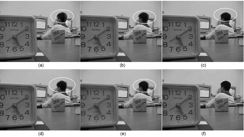
Figure 5. The fused images ‘Rose’ obtained by different fusion mthods: (a)DWT; (b)SF; (c)RPCA; (d)PCNN1; (e)PCNN2; (f)Proposed
Figure7. The differrence imagesbetween the far focused source image ‘Lab’ and their corresponding fused imagesobtained by different fusion mthods: (a)DWT; (b)SF; (c)RPCA;
(d)PCNN1; (e)PCNN2; (f)Proposed
Inspecting the rose and the wall in Figure 5, the contrast of the fused image of DWT is worse than that of the SF, RPCA and the proposed method, and the contrast of the fused image of proposed method is better than that of the fused images of the other fusion methods mentioned above. There are some blurry regions on the wall in the fused images of PCNN1 and PCNN2, respectively. Moreover, the obvious blocking artifacts and small blurry regions appear on the door frame in the fused image of SF and RPCA, respectively. Inspecting the student and the clock in Figure 6, the student’s head in the fused image of DWT shows obviously artifacts. A narrow prominent appears on the upper edge of the student’s head in the fused image of RPCA. Blocking artifacts appear on the left and right edge of student’s head in the fused images of PCNN1 and SF, respectively. The obvious artifact appears on the right edge of the student’s head in the fused images of PCNN2. In Figure 7, mis-registration and distortion are obviously observed in the difference image of DWT. There are some obvious blocking artifacts in the difference image of SF and PCNN1, respectively. There are some obvious image residual in the right of the difference images of RPCA and PCNN2, respectively. Thus, the fused image of the proposed method achieves superior visual performance by containing all the focused contents from the source images. But it should be noted that there are also little blocking artifacts in the edge of clock in Figure 7(f). We attribute this to the fixed size of the structure element Z. To eliminate the thin protrusions, narrow breaks, thin gulfs, small holes, etc. in decision matrix H, the morphological operations are performed on decision matrix H by using the structure element Z with fixed size. The morphological operations lack adaptability for the fixed size of the structure element Z. It cannot eliminate the thin protrusions, narrow breaks, thin gulfs, small holes, etc. in decision matrix H completely.
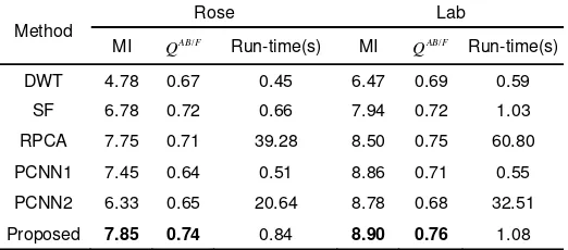
4.2. Quantative Analysis
For quantitative comparison, the quantitative results in two quality measures are shown in Table 1. The proposed method gains highest MI [27] and AB F/
that of the block division used in the proposed method. But the proposed method still yields longer computational cost than DWT-based fusion method and SF-based fusion method, and the matrix decomposition accounts for the majority of the computational load.
Table 1.The performance of different fusion methods
Method
In this paper, a novel fusion method is proposed to effectively extract the focused regions and improve the quality of the fused image. The qualitative and quantitative analysis show that the proposed method achieves superior fusion results compared to some existing fusion methods and significantly improves the quality of the fused image. In the future, we will consider optimizing the proposed method to reduce the time-consuming and improving the adaptivity of the proposed method.
Acknowledgements
The work was supported by National Key Technology Science and Technique Support Program (No. 2013BAH49F03), Key Technologies R&D Program of Henan Province (No. 142102210637), the National Nature Science Foundation of China (No. 61379010), and the Natural Science Basic Research Plan in ShaanxiProvince of China (No. 2012JQ1012).
References
[1] HJ Zhao, ZW Shang, YY Tang, B Fang. Multi-focus image fusion based on the neighbor distance.
Pattern Recognition. 2013; 46(3): 1002-1011.
[2] ST Li, XD Kang, JW Hu, B Yang. Image matting for fusion of multi-focus images in dynamic scenes.
Information Fusion. 2013; 14: 147-162.
[3] H Hariharan. Extending Depth of Field via Multi-focus Fusion. PhD Thesis. University of Tennessee,
Knoxville. 2011.
[4] R Eckhorn, HJ Reitboeck, M Arndt, PW Dicke. Feature linking via synchronization among distributed assemblies: Simulation of results from cat cortex. Neural Computation.1990; 2: 293-307.
[5] RP Broussard, SK Rogers, ME Oxley, GL Tarr. Physiologically motivated image fusion for object
detection using a pulse coupled neural network. IEEE Transaction Neural Networks.1999; 10:
554-563.
[6] JL Johnson, HS Ranganath, G Kuntimad, HJ Caulfield. Pulse coupled neuralnetworks. Neural
Networks and Pattern Recognition. 1998: 1-56.
[7] ZB Wang, YD Ma, FY Cheng, LZ Yang. Review of pulse-coupled neural networks. Image and Vision
Computing. 2010; 28(1): 5-13.
[8] QG Miao, BS Wang. A Novel Adaptive Multi-focus Image Fusion Algorithm Based on PCNN and
Sharpness. SPIE 2005: Sensors, and Command, Control, Communications, and Intelligence (C3I) Technologies for Homeland Security and Homeland Defense IV, Edward M. Carapezza, Editor. 2005: 704-712.
[9] W Huang, ZL Jing. Multi-focus image fusion using pulse coupled neural network. Pattern Recognition
Letters. 2007; 28 (9): 1123-1132.
[10] XB Qu, JW Yan, HZ Xiao, ZQ Zhu. Image Fusion Algorithm Based on Spatial Frequency-Motivated
Pulse Coupled Neural Networks in Nonsubsampled Contourlet Transform Domain. Acta Automatica
Sinica. 2008; 34(2): 1508-1514.
[15] T Wan, CC Zhub, ZC Qin. Multifocus Image Fusion Based on Robust Principal Component Analysis.
Pattern Recognition Letters. 2013; 34(9): 1001-1008.
[16] J Wright, A Ganesh, S Rao, Y Ma. Robust principal component analysis: Exactrecovery of corrupted
low-rank matrices via convex optimization. Proceedings of Advances in neural information processing systems. 2009: 2080-2088.
[17] Z Lin, M Chen, L Wu, Y Ma.The augmented Lagrange multi-plier method for exact recovery of
corrupted low-rank matrices. UIUC Technical Report UILU-ENG-09-2215. 2009.
[18] W Huang, Z Jing. Evaluation of focus measures in multi-focus image fusion. Pattern Recognition
Letters. 2007; 28(4): 493-500.
[19] Y Jiang, M Wang. Image fusion with morphological component analysis. Information Fusion. 2014;
18: 107-118.
[20] B Yang, ST Li. Multi-focus image fusion based on spatial frequency and morphological operators.
Chinese Optics Letters. 2007; 5(8): 452-453. [21] http://www.ece.lehigh.edu/spcrl. 2005.
[22] http://www.imgfsr.com/sitebuilder/images. 2009.
[23] S Li, JT Kwok, Y Wang. Combination of images with diverse focuses using the spatial frequency.
Information fusion. 2001; 2(3): 169-176.
[24] Image fusion toolbox: http://www.imagefusion.org/.
[25] RPCA toolbox:http://perception.csl.illinois.edu/matrix-rank/sample_code.html. [26] PCNN toolbox: http://quxiaobo.go.8866.org/project/PCNN/PCNN_toolbox.rar.
[27] DJC MacKay. Information theory, inference and learning algorithms.Cambridge university press.
2003.
[28] CS Xydeas, V Petrovic. Objective image fusion performance measure. Electronics Letters. 2000; 36: