17 Dec 2012
A CONVERSION OF ICE SYSTEM INTO ELECTRIC VEHICLE
Kasrul Abdul Karim1,a*, Md Nazri Othman2 , Abdul Rahim Abdullah3 , Mohd Zulkifli Ramli4 and Auzani Jidin4
1,2,3,4 Universiti Teknikal Malaysia Melaka/FKE, Melaka, Malaysia. a
Email: [email protected]
Abstract— Nowadays, an electric vehicle (EV) is increasingly
popular among researchers and professionals due to greenhouse gas emission issues and energy supply shortage in coming years. However, the development of the EV through conversion method is still cloudy to general peoples. This paper depicts the development of converting the commercial internal combustion engine (ICE) based donor vehicle into the electric vehicle while retaining its original transmission. The aim is to provide the minimum step of conversion process without ignoring the safety aspect. The conversion method is described step-by-step to provide better understanding to the reader. The conversion process begins with the disassembling of combustion engine while the transmission box is remained in place. The electric motor-transmission coupling plates which consist of inner and outer parts are designed as accurate as possible based on the shape and measurement of both shaft and chassis. The controller unit is the heart and brain of the EV will do all the heavy lifting by interlink the batteries with the electric motor. The batteries that consist of several Lithium Polymer (LiPo) cell will provide all the energy to power up the controller and to drive the electric motor. The interaction between this three components (batteries, controller and electric motor) as well as safety issue is thoroughly elaborated. At the end, the performances of completed EV with high acceleration rate is analyzed and presented.
Keywords—electric vehicle, conversion, controller, lithium polymer, coupling plate.
I. INTRODUCTION
The interests on electric vehicle development are significantly increased in this decade. This is due to the awareness of the environmental issue such as zero emission advantages of the EV. It also due to significant increased of oil prices and the limitation of the oil sources in these decades [1-12].
These factors urge the world to find alternative and boost the research and development of EV. Typically, there are three types of EV development;
1. Commercial EV 2. Commercial Hybrid EV 3. Conversion EV
The commercial EV development commonly involved big automotive companies which able to design and build passenger vehicles from chassis to entire system in meeting the standard policy and requirement. These kinds of vehicles are available now such as Nissan Leaf and Ford Focus with reasonable distance range [2]. On top of that, commercial HEV are considered more mature as hybrid car likes Toyota Prius and Honda Insight already sold around the world [2,5,6]. The third type of EV development, which is known as conversion
involving process of replacing petroleum based internal combustion engine (ICE) into electric car while maintaining the original structure [1,9,10].
This paper will describe the step of converting conventional ICE passenger car into fully electric vehicle that solely used the batteries as a power source. In addition to batteries, some basic equipment is required to accomplish the task such as electric motor, the controller, throttle, relays, and switches. The engine of the donor car is disassembled from its transmission box and replaced with electric motor to spin the wheels. The controller serves as the heart and brain of the system located between the batteries and the electric motor.
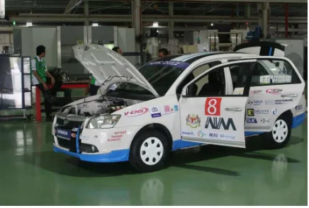
This conversion EV is designed and constructed to participate in the Proton Green Mobility Challenge (PGMC) 2012 that held at F1 Sepang circuit. The EV is successfully tested on 4 challenges namely farthest distance, quarter mile acceleration, fastest two laps and the top speed. This EV also provides a platform for the staff and student to improve the research on this field. The research and development of this vehicle will still continue especially on the regenerative braking, battery management system, new electric motor topology with its dedicated drive and also in thermal management system.
Figure 1. Developed Electric Car
II. COMPONENT OF ELECTRIC CAR
17 Dec 2012
system to drive the induction motor, the throttle unit to input speed demand to the controller and a unit of 12V gel cell battery to power up all the relays and the vacuum pump. The relay unit provides safety features by enabling the low current side to switch on and off the high current side of the system. The vacuum pump is necessary to provide the adequate pressure to the braking system in order to stop the car when needed. The concept of the interconnection between the components in the electric car is shown in Figure 2.
Figure 2. Components interconnection diagram
III. ELECTRIC CAR WORKING PRINCIPLE
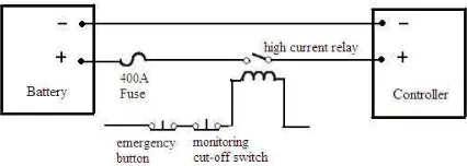
The controller that serves as heart and brain the electric car system is connected to the LiPo battery pack through series of safety devices as shown in Figure 3. The automotive grade fuse rated 400A with complete transparent cover is to confine the sparking in case blown fuse due to over current. The high current relay provides the isolation switching to the low current side. The emergency push button is installed within the reach of the driver to allow the relay to be cut off at any necessary time. Since the controller have internal protection, soft start circuit to avoid or minimize high inrush current are not required. In addition, due to wiring requirement for EV [8], the cable itself is automotive grade that able to withstand high temperature and high current up to 500A.
Figure 3. The controller to LiPo battery pack wiring
diagram
The controller converts the battery DC power to 3-phase AC by utilizing Pulse Width Modulation (PWM) technique. The controller is connected to the induction motor using three high current cables And in order to achieve precision control, the rotor position of the motor is captured using two quadrature encoders for phase A and phase B mounted on the motor shaft. Motor speed
and direction that are simultaneously sensed by the quadrature encoder are the primary feedback signal used in the motor control algorithm. The controller drives the induction motor up to the demand speed based on generated low voltage input by pressing the foot throttle. It is important to make sure that the maximum throttle voltage and the throttle resistance is matching with controller specification. Typically, the maximum throttle voltage is 5VDC with maximum resistance of 5k ohm [7].
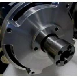
The induction motor is mounted on the transmission box by using custom made aluminium coupling plate to ensure lightweight and durability. The induction motor used has enough starting torque to rotate the front wheel and drive the car forward.
Figure 4. Electric car working principle
IV. ELECTRIC CAR DEVELOPMENT
In this project, the developments works can be grouped into five important tasks namely motor-transmission coupling, electric motor control, battery, monitoring system and thermal management. Each task can be performed in parallel or in sequences depending on available numbers of people.
A. Motor-transmission coupling
17 Dec 2012
introduced to absorb vibration during movement due to uneven terrain.
The original clutch and transmission box still in place to provide flexibility for the user to change gear ratio as for conventional even though is not necessarily required.
Figure 5. Shaft coupler
Figure 6. Adapter plate and additional support
B. Electric motor control
The induction motor and the controller unit are selected over Permanent Magnet (PM) motor due to the lower cost and widely available as conversion kit for professional and hobbyist [12]. Figure 7 shows the manufacturer performance data of the induction motor.
Figure 7. Induction motor performance characteristic
In order to avoid any damage to the coupling plate, the motor and controller is tested on the lab to verify it functionality. High current power supply is used instead of LiPo battery pack to ensure the current limit is under control. It is also important to avoid unnecessary damage due to the wiring mistake and short circuit on the first implementation. The controller parameter is set to default setting and the other available motion control technique in [4] can be implemented after the challenge is completed.
After successful test on the lab, the motor and controller with all the accessories and wiring are securely fit on the car. To ensure the test is done safely with minimum load, the car is lifted and float on the air for few centimeters from the ground to allow the tires spins freely. Later the car is lowered to the ground and the full test drive can be performed. The electric vacuum pump must be installed to provide an adequate pressure to the braking system as required for the safety reason. Several test drive is necessary to collect the data on power flow, thermal dissipation, battery consumption and mechanical aspect of the car. The captured data combined with the data from the manufacture is used for improvement and to plan the race strategy. This kind of data may also be used to predict the performance of the developed EV [11].
C. Monitoring system
The purpose of the monitoring system is to continuously monitor and capture the important data to be analyzed later. The monitoring system also used to assist the driver on safety aspect and has ability to cut off the main power supply in case of emergency. The concept of monitoring system is shown in Figure 8.
Figure 8. Monitoring system concept
17 Dec 2012
The monitoring system Graphical User Interface (GUI) will display all the necessary information in real time to the driver. The error occurs will be illuminated to the driver with the pre-programmed suggested solution. Some of the critical parameters that closely monitored are DC current from battery, battery voltage level, temperature of electrical motor, individual battery and the controller.
This details monitoring system are not necessary for common user but more for research and development of the electric vehicle. However, the nice GUI exhibits the future trend of the digital technology.
D. Battery
The battery provides the energy required to drive the vehicles. Moreover, the battery efficiency will affect the distance range of the EV [10]. Therefore, the battery is the most important technology in EV industries. The recent research trend is to minimize the physical size while increasing the storage capacity. The LiPo battery is one of the advanced batteries in battery technology. It has different discharge characteristic compared to lead acid battery.
In this project Infineon XC866 microcontroller is used to control the charging process. The charging process involving two stages where on the first stage 13 numbers of modules is charged in series in constant current mode. After certain level of total voltage, second stage takes over by charging the module in smaller group using constant voltage until 100% state of charge (SOC) is reached. This technique ensures that the minimal unbalanced charge between each module can be achieved. On top of that, for safety reason the temperature and voltage level of each individual module is measured at every instant. During discharging, the battery line will be cut off if the voltage level is below the pre-setting discharge cut-off voltage as suggested by the manufacturer.
Figure 10. Infineon XC866 microcontroller based
charging circuit
E. Thermal management
Effective energy utilization is very important in any Electric Vehicle (EV). Therefore, every component in the EV should operate at the at most ideal condition. In order to achieve the ideal operating temperature for these components, efficient thermal management is essential. The purpose of a thermal management system is to deliver optimum power to EV. An ideal thermal management system should be able to maintain the desired uniform temperature by removing the same amount of heat generated by the sources. A thermal management system may use air for heat/cooling/ventilation, liquid for cooling/heating, insulation, thermal storage such as phase change materials, or a combination of these methods. The thermal management system may be passive (i.e., only the ambient environment is used) or active (i.e., a built-in source provides heating and/or cooling at extremely cold or extremely hot temperatures).
In this project, the three major components that produce large amount heat are battery, controller and motor. However, the battery pack is a key component of their fuel savings potential, and the battery is also one of the most expensive components in the vehicle. Thus, the combination of the blowing fan, thermal paste, heatsink and thermal plate is used to discharge the heat from the critical components.
Figure 11. Concept of thermal management
V. RESULT
17 Dec 2012
Figure 12. Monitoring data during test drive
VI. CONCLUSIONS
The design and construction of full EV is presented. The vehicle is constructed using university facilities and equipments. The test drive is performed around the university to capture more data as possible for the analysis. The developed EV is fully functional with future improvement on battery management and also thermal management. The battery management should be improved on charging up individual module instead of smaller group. The use of other cooling method such as liquid or refrigerant cooling could be implemented to achieve lower operation temperature on all critical
components.
ACKNOWLEDGMENT
The author would like to thank Universiti Teknikal Malaysia Melaka (UTeM), Perusahan Automobil Nasional (PROTON), Agensi Inovasi Malaysia (AIM) and all other sponsors for their full support to make this project successful.
REFERENCES
[1] B.C. Keoun, Designing an electric vehicle conversion,
Southcon/95. Conference Record, 1995, pp.303-308.
[2] L. Situ, Electric Vehicle development: The past, present & future, 3rd International Conference on Power Electronics
Systems and Applications, 2009, pp.1-3.
[3] P. Guo, P. Liu, Research on Development of Electric Vehicles in China, International Conference on Future Information
Technology and Management Engineering, 2010, pp. 669-676.
[4] Y. Hori, Y. Toyoda Y.Tsuruoka, Traction control of electric vehicle: basic experimental results using the test EV “UOT electric march”, IEEE Transactions on Industry application, 1998, pp.1131-1138..
[5] F.U. Syed, M.Kuang, and J. Czubay, Fuzzy control to improve high-voltage battery power and engine speed control in a hybrid electric vehicle, Annual Meeting of the North American
Fuzzy Information Processing Society, 2005, pp.343-348.
[6] R. A.P. Asimakopoulos, B.T. Boumis, C.E.Patsias, Experience derived from the conversion of a conventional car to a hybrid electric vehicle -analysis of the powertrain, International
Symposium on Power Electronics Electrical Drives Automation and Motion, 2010, pp. 1040- 1045
[7] Curtis Instrument, 1234/36/38 Manual: AC Induction Motor Controller & VCL, 2006.
[8] K. Nasr, M, Tavakoli, M. Thompson, High speed electric vehicle, Proceedings of the 32nd Intersociety Energy
Conversion Engineering Conference, 1997, pp. 2024-2029.
[9] J.P. Trovao, P.G. Pereirinha, H.M. Jorge, Simulation model and road tests comparative results of a small urban electric vehicle, 35th Annual Conference of IEEE Industrial
Electronics, 2009, pp. 836- 841.
[10] A. Apak, Y. Koyuncuoglu, H. Heceoglu, Design and construction of an electric minibus, IEEE International
Conference on Mechatronics, 2011, pp.84-89
[11] D. Tanaka,T. Ashida, S. Minami, An analytical method of EV velocity profile determination from the power consumption of electric vehicles, IEEE Vehicle Power and Propulsion Conference, 2008, pp.1-3.