HEAT TRANSFER IN AN ARRAY OF STAGGERED TUBE USING COMPUTATIONAL FLUID DYNAMIC(CFD) METHOD
MASTURA BINTI AZMI
This report is submitted
in partial fulfillment for Bachelor of Mechanical Engineering (Thermal-Fluids)
Faculty of Mechanical Engineering Universiti Teknikal Malaysia Melaka
ii
“I declare that all parts of this report are the result of my own work, except a few sections which were extracted from other resources as being mention”
iii
ACKNOWLEDGEMENT
Firstly, I am very grateful to the almighty ALLAH S.W.T for His goodness I can finish this project. I also would like to thank all the persons and groups that have contribute in finishing this project. These persons and groups have given the commitment and contribution that is really important in order to finish this project. Your commitment and cooperation is really appreciated.
Not to forget, the most gratitude towards my supervising lecture, Mr. Syamsul Bahari bin Azraai that has given me much help, teaching, and guidance to me from the beginning until I finish this project. Other than that, he also gives me a lot of support and suggestion in order for me to solve the problem in finishing this project. His teaching and guidance that is given to me is very precious.
I also want to thank the University for giving me the chance to gain experience and knowledge during the project. The facility provided by the University is very essential to assist me in the finishing of this project. I would like to thank to all the staff at the library and cyber room for their cooperation and contribution. It would be very hard for me if I have not been assist by them. All the references provided are very useful for this project.
iv
ABSTRACT
v
ABSTRAK
vi
TABLE OF CONTENT
CHAPTER TOPIC PAGE
DECLARATION ii
ACKNOWLEDGEMENT iii
ABSTRACT iv
TABLE OF CONTENTS vi
LIST OF TABLES ix
LIST OF FIGURES x
LIST OF APPENDIXES xii
LIST OF SYMBOLS xiii
LIST OF ABBREVIATIONS xv
1 INTRODUCTION 1.1 Background of Project 1
1.2 Objectives 4
1.3 Problem Statement 4
1.4 Scopes 5
1.5 Benefit of Study 5
vii
2.2.1 Research Article 1 8
2.2.2 Research Article 2 9
2.2.3 Research Article 3 10
2.2.4 Research Article 4 11
2.2.5 Research Article 5 12
2.3 Computational Fluid Dynamics
2.3.1 Introduction o CFD-FLUENT 12
2.3.2 The benefits of CFD 14
2.3.3 Disadvantages of CFD 15
2.3.4 Governing Equation 16
2.3.4 Heat Transfer Formula in Staggered tube 18
3 METHODOLOGY
3.1 Introduction 24
3.2 Computational Fluid Dynamic,(CFD) 26
3.2.1 Simulation Procedure 26 3.2.2 Computational Geometry, Domain and Meshing 27
3.2.3 Boundary Conditions 30
3.2.4 Post Processing 33
3.3Experimental Setup 33
4 NUMERICAL RESULT AND DISCUSSION
4.0 Introduction 37
4.1 Simulation Result 37
4.1.1 Temperature Profiles at Different Transverse Pitch 38 to Diameter Ratio.
viii
4.1.3 Analysis Result According to Velocity Magnitude 41 Contours
4.2 Comparison Between Experimental Result and Simulation 41 Result
5 CONCLUSSION AND SUGGESTION
5.1 Conclussion 49
5.2 Suggestion and Recommendation 50
REFERENCES 51
APPENDIX A 54
APPENDIX B 61
ix
LIST OF TABLES
NO TOPIC PAGE
3.1 Geometry parameter for staggered tube 29
3.2 Types of Boundary Condition 31
3.3 Setting parameter for simulation Case B 31 3.4 Shows the properties of air and aluminium 32 4.1 Temperature rise with varying the transverse pitch to diameter 39
ratio,(ST/D).
4.2 Pressure drop with varying the transverse pitch to diameter ratio 41 4.3 Velocity rise varying with the transverse pitch to diameter ratio 43 4.4 Numerical result analysis at four different cases 44 4.5 Forced convection result for simulation and experimental result 48
x
LIST OF FIGURES
NO TOPIC PAGE
1.1 Schematic cross-section of the tube arrays used in investigation 3 1.2 The location of staggered tube in air conditioning 4
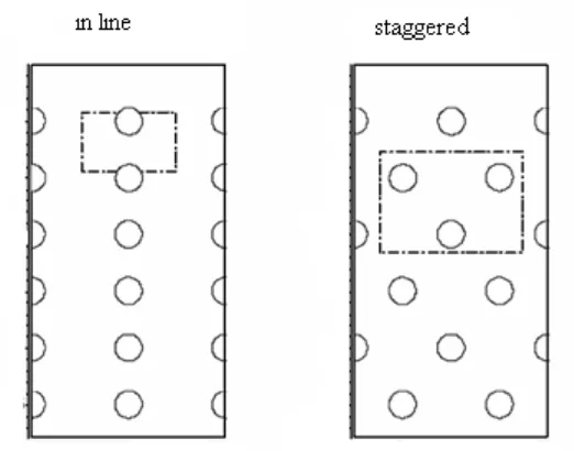
2.1 Arrangement of the tubes in staggered and in-line tube banks 21
3.1 Overall Methodology Chart 25
3.2 Basic program structure 26
3.3 Schematic Drawing of Air Flows across staggered tube 28
3.4 2-D model of staggered tube in GAMBIT 28
3.5 Gambit meshed (approximately 27232 triangular cell) in a 29 staggered tube bundle with ST/D=2.0
3.6 Boundary type of staggered tube bundle 30
3.7 Continum type(solid) of staggered tube bundle 30 3.8 Residual graph for governing equations 32 3.9 Schematic Drawing of Air Flows across staggered tube 34 4.0 Schematic drawing for forced convection unit setup 35 4.1 Contours of static temperature(K) across an array of staggered 38
heated tube for 2-D model
4.3 Contours velocity magnitude(m/s) across an array of staggered 42 heated tube
xi
4.5 Contours of static pressure (Pascal) across an array of staggered heated 45
tube for 2-D model
4.6 Contours of velocity magnitude (m/s) across an array of staggered 45 heated tube for 2-D model
4.7 Comparison of simulation results and experimental result at 46 different Reynolds number.
xii
LIST OF APPENDIXES
NO TOPIC PAGE
A Experimental Result 54
B Table properties 61
xiii
LIST OF SYMBOLS
= heat transferred rate, W
Cp = constant pressure specific heat, J/kg.K Tw = wall temperature, K
Ts = suface temperature, K
Tin = Hot stream of inlet temperature, K Tout = Hot stream of outlet temperature, K T∞ = fluid free stream temperature,K ρAir = the density of air, kg/m3
ρ = density, kg/m3
v = kinematic viscosity of air, kg/ms
w = the flow rate over entire cross sectional area, W
N = number of tube
∆T = The temperature difference cpL = the specific heat capacity
Pel = amount of energy, W
α = heat transfer coefficient Tavg = Average temperature Cc = specific heat for cold fluid Ch = specific heat for hot fluid
kf, = air thermal conductivity evaluated at Tf Cmin = smaller specific heat
xiv
U = overall heat transfer coefficient
Fp = Fin pitch, mm
Ft = Fin thickness, mm
S1 = tube span wise pitch
SD = Diagonal pitch, mm
SL = Longitudinal pitch, mm
ST = Transverse pitch, mm
h = Convection heat transfer coefficient, W/m2.K
h = spesific enthalpy, kJ/kg
k = thermal conductivity, W/mK
= Dynamic viscosity
F = Correction factor
ST* = Transverse pitch to diameter ratio SL* = Longitudinal pitch to diameter ratio NuD = Nusselt number based on diameter
NuD,NL = Nusselt number based on diameter and numbers of tubes
Pr = Prandtl number
ReD = Reynolds number
Ma = Mach number
∆P = static pressure drop, Pa
Nu = Nusselt number
AS = Surface area, m2
A = Area, m2
V = velocity, m/s
D = diameter, mm
L = length of tube, mm
xv
LIST OF ABREVIATION
DM = Design Modeler
CAD = Computer Aided Design GGI = Generalized Grid Interface CFD = Computational Fluid Dynamic RANS = Reynolds–Averaged Navier–Stokes CAE = Computer Aaided Eengineering NTU = Number of Transfer Units
LMTD = Log Mean Temperature Different
2-D = Two -dimensional
3-D = Three –dimensional
1
CHAPTER 1
INTRODUCTION
1.1 Background of Project
Heat transfer is the kind of energy transfer that may take place between material bodies as a result of a temperature difference from a hot to a colder body in such a way that the body and surroundings reach thermal equilibrium. Heat transfer always occurs from a hot body to a cold one as a result of the second law of thermodynamic. Where there is a temperature difference between objects in proximity, heat transfer between them can never be stopped; it can only be slowed down..The driving force for heat transfer is the difference in temperature levels between the hot and cold fluids, the greater the difference the higher the rate at which the heat will flow between them. With complex processing sequences the designer must optimize the temperature levels at each stage to maximize the total rate of heat flow.
2
Radiation is the transfer of heat through electromagnetic radiation. Hot or cold, all objects radiate energy at a rate equal to their emissivity times the rate at which energy would radiate from them if they were a black body. No medium is necessary for radiation to occur; radiation works even in and through a perfect vacuum. The energy from the Sun travels through the vacuum of space before warming the earth. Also, the only way that energy can leave earth is by being radiated to space.
Convection is a combination of conduction and the transfer of thermal energy by fluid circulation or movement of the hot particles in bulk to cooler areas in a material medium. There are two type of convection process which is free convection and force convection. When heat is carried by the circulation of fluids due to buoyancy from density changes induced by heating itself, then the process is known as free convection heat transfer. But for my case study, it is focused on forced convection heat transfer. Forced convection occurs when pumps or fans or other means are used to propel the fluid and create an artificially induced convection current.
The phenomena of heat transfer plays an important role in many industrial applications. The design of virtually all systems require the application of heat transfer principles. This includes applications in the automotive, computer, and aerospace industries. Automotive engineers are constantly being challenged in designing vehicles that may involve increasing the heat rejection of the radiator, shielding components from the hot exhaust manifold and pipes, or to increase cooling around the brake rotors. Cooling of sensitive electronic components in computers, the internal combustion of rockets, satellites, HVAC systems, microwaves, power plants, housing insulation, and underground water pipes are several other areas where heat transfer must be addressed. Clearly, the list of applications can be extended considerably. It is a subject with a widespread of importance in our everyday life.
3
equipment have their specific life spent of heat. Others, it also importance to avoid from dangers and waste. So, we should design the heat exchanger with the application of pitch to diameter ratio to enhanced the heat transfer rate across it.
The cross-flow over tube arrays has wide practical applications in the design of heat exchangers, in flow across over head cables, in cooling systems for nuclear power plants and in cooling system in steam generation power plant. For these reasons, numerous measurements of cross flow in tube bundles have been made to advanced a physical understanding of such flows. There have been a considerable amount of theoretical and experimental work committed to the studies of different aspects of flow around in in-lined tube bundles, staggered tube bundles or in asymmetric tube bundles the arrangements. Experimental studies on flows in tube bundles focused on measurement of heat transfer and pressure drop and discussion the characteristics of the flow across tube bundle at different pitch to diameter ratio.
[image:19.595.188.449.527.732.2]There are two different tube bundle arrangement in predicting the air flows across tube bundle which is in line tube bundle and staggered tube bundle. Both arrangement may result to the different heat transfer performance and heat flow characteristic. Staggered tube arrangement have higher heat transfer performance compared to in line tube its higher surface area exposed to environment. Schematic drawing of in line and staggered tube bundle are shows as Figure 1.1.
4
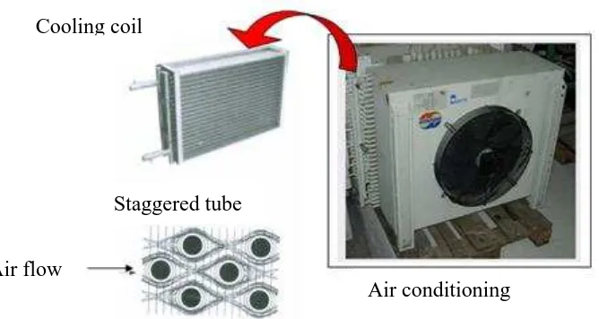
Figure 1.2: The location of staggered tube in air conditioning. (Source: DUNHAM)-BUSH Catalog)
1.2 Objective
The objective of this project is as below:
a) To determine the heat transfer in an array of staggered tube tube at different transverse pitch to diameter ratio.
b) To validate the simulation result with experimental result.
1.2.1 Problem Statement
Tube arrays are scale models of typical heat exchanger geometries (condenser) for cooling system in aircon. Type of arrangement of tube bundle with their pitch to diameter ratio can effect the performance of heat exchanger. To overcoming this problem, CFD simulation is used to simulate air flow across an array of staggered tube bundle. From the CFD result, we choose the optimum parameters pitch to diameter ratio. After CFD simulation running we can optimum transverse pitch to diameter ratio with to the higher performance of heat transfer rate.
Air conditioning Air flow
5
Experimental result will be used to validate the CFD simulation result with both geometrical parameters are fixed.
Cross flow in a tube bundles has application in design of heat exchanger for cooling system. In order to design it, we have to investigate heat transfer air flow in an array of staggered tube regarding with their geometrical parameters especially at a pitch to diameter ratio to optimizing the heat transfer across it.
1.5 Scopes
a) The scope of this project is to construct two dimensional(2-D) staggered tube Computational Fluid Dynamic(CFD) geometry.
b) To simulate periodically air flow around the bundle of staggered tube, c) To set-up the experimental work and
d) To compute both result between experimental and simulation result.
1.6 Benefit of study
6
CHAPTER 2
LITERATURE REVIEW
2.1 Introduction
The development of certain project needs to be done systematically and does not exceed the time limit. In order to solve this problem, a concrete planning needs to be done. There are a few things that need to be taken off when doing research to complete this chapter. Literature reviews are important to know what the other researches achieved during their research on the related investigations. From that, the comparison between experimental and simulations results can be achieved to evaluate a good conclusion.
The heat exchangers are thermal equipment present in almost all industrial sectors, playing an essential role in many processes and systems. Increasing the efficiency of this equipment determines functioning conditions and performance of technological assemblies. Heat transfer to or from a bundle of tubes in cross flow is relevant to numerous industrial applications such as steam generation in a boiler or air cooling in the coil of an air conditioner.
7
evaluation of the convective heat transfer coefficients [1]. The characteristics of the heat exchanger can be established wither directly by experimental measurements or by numerical simulations. The experimental measurements are needed in order to develop new the new heat exchanger designs, and for the establishment of the optimal operational parameters [2]. In the case of a gas, which in my case is air, flowing throughout a bundle of tubes, the assessment of the effective heat transfer coefficient is very important seeing that in general there are the lowest convective heat transfer coefficients, which influence the effective global heat transfer coefficients. Making a piece of equipment as compact as possible for obtaining a heat transfer rate as big as possible is the main concern in the research activity of heat exchangers.
Previous study of An Experimental and Numerical Investigation of Tube Bank Heat Exchanger Thermofluids proposes and assesses the effectiveness of a dual design strategy, which combines empirical and numerical analyses of heat exchanger thermofluid performance. Empirical analysis serves to provide initial design specifications, while performance is optimized using CFD. The test vehicle consists of a staggered tube bank heat exchanger arrangement (ST* = SL* = 3.0). Good agreement is obtained between the empirical relationships developed by Martin [3] for heat transfer and Gaddis and Gnielinski [4] for pressure drop, and corresponding CFD predictions for Reynolds numbers varying from 1,749 to 17,491. Numerical flow field predictions are found to be accurately predicted relative to particle image velocimetry(PIV) measurements for a Reynolds number of 700. This study therefore provides a degree of confidence in using empirical correlations to undertake an initial sizing of tube bank heat exchanger design, to be refined for application specific environments using CFD analysis.
8
turbulent eddy diffusivity. Scalar turbulent dispersion from a line heat source is studied for moderate and high Prandtl number fluids.
2.2 Previous study
2.2.1 Research Article 1
Experimental and numerical investigation of turbulent cross-flow in a staggered
tube bundle by S.S Paul, S.J. Ormiston, and M.F Tachie, Department of
Mechanical and Manufacturing Engineering, University of Manitoba Canada.
This paper presents the results of measurements and numerical predictions of turbulent cross-flow in a staggered tube bundle. The bundle consists of transverse and longitudinal pitch-to-diameter ratios of 3.8 and 2.1, respectively.
The experiments were conducted using a particle image velocimetry technique, in a flow of water in a channel at a Reynolds number of 9300 based on the inlet velocity and the tube diameter. A commercial CFD code, ANSYS CFX V10.0, is used to predict the turbulent flow in the bundle. The steady and isothermal Reynolds–Averaged Navier–Stokes (RANS) equations were used to predict the turbulent flow using each of the following four turbulence models: a k-epsilon, a standard k-omega, a k-omega-based shear stress transport, and an epsilon-based second moment closure. The epsilon-based models used a scalable wall function and the omega-based models used a wall treatment that switches automatically between low-Reynolds and standard wall function formulations.