INPUT SHAPING FOR VIBRATION-FREE POSITIONING OF FLEXIBLE MANIPULATOR SYSTEMS
MOHD SUFIAN BIN ABDUL KARIM
This report is submitted in partial fulfillment of the requirements for the award of Bachelor of Electronics Engineering (Industrial Electronics) With Honours
Faculty of Electronic and Computer Engineering Universiti Teknikal Malaysia Melaka
UNIVERSTI TEKNIKAL MALAYSIA MELAKA
FAKULTI KEJURUTERAAN ELEKTRONIK DAN KEJURUTERAAN KOMPUTER
BORANG PENGESAHAN STATUS LAPORAN PROJEK SARJANA MUDA II
Tajuk Projek :
INPUT SHAPING FOR VIBRATION-FREE POSITIONING OF FLEXIBLE MANIPULATOR SYSTEMS
Sesi Pengajian : 2006 - 2009
Saya MOHD SUFIAN BIN ABDUL KARIM mengaku membenarkan Laporan Projek Sarjana Muda ini disimpan di Perpustakaan dengan syarat-syarat kegunaan seperti berikut:
1. Laporan adalah hakmilik Universiti Teknikal Malaysia Melaka. 2. Perpustakaan dibenarkan membuat salinan untuk tujuan pengajian sahaja.
3. Perpustakaan dibenarkan membuat salinan laporan ini sebagai bahan pertukaran antara institusi pengajian tinggi. 4. Sila tandakan ( √ ) :
SULIT*
(Mengandungi maklumat yang berdarjah keselamatan atau kepentingan Malaysia seperti yang termaktub di dalam AKTA RAHSIA RASMI 1972)
TERHAD* (Mengandungi maklumat terhad yang telah ditentukan oleh
organisasi/badan di mana penyelidikan dijalankan)
TIDAK TERHAD
Disahkan oleh:
__________ _______________
________________________________ (TANDATANGAN PENULIS) (COP DAN TANDATANGAN PENYELIA) Alamat tetap: F2 Kg. Batu Hitam
36800 Kg. Gajah Perak.
iii
”I hereby declare that this report is the result of myown work except for quotes as cited in the references.”
iv
”I hereby declare that I have read this report and in my opinion this report is sufficient in terms of the scope and quality for the award of Bachelor of Electronic Engineering
(Industrial Electronics) With Honours.”
Signature : ...
Supervisor’s Name : PN. AZDIANA BT. MD. YUSOP
v
vi
ACKNOWLEDGEMENT
The author wishes his indebted acknowledge to meet all those who contributed to the emergence, creation and correction of this thesis. There is no question that who should get top billing. Thank a lot especially to Pn. Azdiana Bt. Md. Yusop for his remarkable ideas, guidance, comments, criticisms and patience to complete this thesis.
vii
ABSTRACT
viii
ABSTRAK
ix
TABLE OF CONTENTS
CHAPTER TITLE PAGE
PROJECT TITLE i
DECLARATION iii
DEDICATION v
ACKNOWLEDGEMENT vi
ABSTRACT vii
ABSTRAK viii
TABLE OF CONTENTS ix
LIST OF FIGURE xii
LIST OF APPENDICES xv
LIST OF SYMBOLS xiv
I INTRODUCTION 1.1 Project Introduction 1
1.2 Background of the Problems 2
1.3 Statement of the Problems 3
1.4Objective of the Study 5
1.5Scope of Study 6
1.5.1 Significance of Study 6
x
II LITERATURE REVIEW
2.1 Introduction 9
2.2 Review of Input Shaping Method 9
2.3 Summary 15
III DEVELOPMENT OF INPUT SHAPING CONTROL
TECHNIQUE USING INVERSE DYNAMICS
3.1Inverse Dynamics 18
3.2 Desired Motion 19
IV MODELLING OF A FLEXIBLE MANIPULATOR
SYSTEM
4.1 The Flexible Manipulator System 23
4.1.1 Modeling of the Flexible Manipulator 25 4.2 Derivation of the Equation of Motion 26
V SIMULATION RESULT AND ANALYSIS
5.1 Matlab 30
5.2 Simulink 31
xi
5.4 Simulation Results 35
5.5 Discussion 40
VI CONCLUSION AND FUTURE WORK
6.1 Conclusion 41
6.2 Future Work 42
REFERENCES 44
xii
LIST OF FIGURES
NO TITLE PAGE
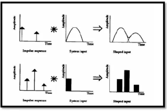
1.1 Convolution of an impulse sequence with a system input 5
3.1 System models used in the examples 18
3.2 Characteristics of the purposed output function 22
4.1 Description of the manipulator system 24
4.2 Overview of the flexible manipulator 24
4.3 Input variable for the system 27
5.1 Input shaping parameters 33
5.2 Block parameters for expression of the motion 34
5.3 Overview for the system developed 34
5.4 Parameters and matrix equation for the systems 35
5.5 Overview of the system developed 36
5.6 Block parameters gain Matrix A 37
5.7 Block parameters gain Matrix B 37
5.8 Block parameters gain Matrix K for stabilize the system 38
5.9 Input shaping waveform 38
5.10 Output waveform for end-point displacement 39
xiii
LIST OF APPENDICES
NO TITLE PAGE
A One link flexible manipulator 47
xiv
LIST OF SYMBOLS
τ - Torque
t - Time
s - Second
E - Young Modulus
I - Area moment of inertia
A - Cross sectional area
ρ - Mass density per unit volume
�ℎ - Hub inertia
� - Mass matrix
� - Stiffness matrix
N - Number of element
L - Length of element
F - Vector of external force
Q - Nodal displacement vector
Θ - Angular displacement
-Velocity
- Acceleration
� - Angular Velocity
CHAPTER 1
INTRODUCTION
1.1 Introduction
2
However, the control of flexible robot manipulators to maintain accurate positioning is an extremely challenging problem. Due to the flexible nature and distributed characteristic of the system, the dynamics are highly non-linear and complex. Problems arise due to precise positioning requirement, vibration due to system flexibility, the difficulty in obtaining accurate model of the system and non minimum phase characteristics of the system (Piedboeuf et al, 1983; Yurkovich, 1992). Therefore, flexible manipulators have not been favored in production industries, as the manipulator is required to have reasonable end-point accuracy in response to input commands. In this respect, a control mechanism that accounts for both rigid body and flexural motions of the system is required. If the advantages associated with lightness are not to be sacrificed, accurate models and efficient controllers have to be developed (Mohamed, Tokhi, 2004).
1.2 Background of the Problems
Control of machines that exhibit flexibility becomes important when designers attempt to push the state of the art with faster and lighter machines. Many researches have examined different controller configurations in order to control machines without exciting resonances. However, after designing a good controller, the input commands to the closed-loop system are ‘desired’ trajectories that the controller treats as disturbances. Often these ‘desired’ trajectories are step inputs or trajectories that the machine cannot rigidly follow (Singer and Seering, 1989).
3
usually caused by changes in the reference command or from external disturbance. If the system dynamics are known, commands can be generated that will cancel the vibration from the system’s flexible modes (Bhat and Miu, 1990; Singer, 1989; Singer and Seering, 1990; Smith, 1957). Accurate control of flexible structures is an important and difficult problem and hasbeen an active area of research (Book, 1993; Junkins and Kim, 1993).
1.3 Statement of the Problems
Vibration is a concern of virtually every engineering disciple; mechanical engineers continually face the problem of vibration because mechanical systems vibrate when performance is pushed to the limit. The typical engineering solutions to vibration are to design ‘stiff’ systems, add damping to flexible system, or develop a good controller. Input shaping is another possibility for vibration control that can supplement methods (Singhose et al., 1990).
Plump et al. (1987) have examined the use of piezoresistive polymer films to generate additional damping in a structure. Albert Thomas et al. (1985) have used a thin layer of viscoelastic material to obtain passive damping that has enhanced system stability. Crawley et al. (1986) have examined the use of a distributed array of piezoelectric device for actuation on a structure. Cannon et al. (1984) have examined feedback control with non collocated end-point position measurements for a single link flexible robot. Hollars et al. (1986) have compared four different control strategies for a two-link robot with elastic drives. Kotnik et al. (1998) have examined feedback acceleration techniques for residual vibration reduction.
4
in time. The result is a reduced settling time for the system. Optimal control approaches have also been used to generate input profiles for commanding vibratory systems. Junkins et al. (1986) and Chun et al. (1985) have also made considerable progress towards practical solutions of the optimal control formulation for flexible systems. Gupta and Narendra (1980), and Junkins et al. (1986) have included some frequency shaping terms in the optimal formulation. Farrenkopf (1979) has developed velocity shaping techniques for flexible spacecraft. Swigert (1980) demonstrated that torque shaping modeling decomposes into second order harmonics oscillators.
5
Figure 1.1: Convolution of an impulse sequence with a system input
The shaping method is effective in reducing vibration in both open and closed loop systems. The selection of amplitude and time location of the impulse is very crucial and affects the system. If the parameters do not match the cancellation of the vibration, the system’s vibration might be increased. Therefore, optimization of the input shaping is needed to achieve better performance of the flexible manipulator.
1.4 Objective of the Study
(a) To study the dynamic characteristic of the flexible manipulator in order to construct the controlling method to reduce the vibration.
(b) To introduce a new method in determining the optimal input shaping using inverse dynamics.
(c) To study the performance of a new method for vibration control of a flexible robot manipulator.
6
Some assumptions and limitations are made along the study to reduce the complexity in solving the problem.
1.5 Scope of Study
The scope of study is divided into three main parts. The first part is to study the previous research regarding the existing methods in vibration reduction for flexible robot manipulators. The flexible manipulator system considered in this work is a single-link flexible manipulator that moves in a horizontal plane.
The second part of the project is to study the dynamic characteristics of the flexible manipulator (Martins et al., 2003). The existing dynamic model of the system using inverse dynamics method will be used. The study is done to understand the dynamic behaviors of the flexible manipulator system. This is very an important part of the research in order to design a good controller for the system. The third part of study is to design a suitable input shaper to control the flexible manipulator system. A new approach in designing input shaper methods will be introduced and optimized for reduction in vibration for flexible manipulator system. This work will be carried out through simulation and optimizes the continuity of previous research (Mohamed and Tokhi, 2004).
1.5.1 Significance of Study
7
manipulator system to maintain accurate position. The implication of the reduction of vibration in flexible manipulator system using the optimal input shaping enables it to be introduced in space structures, flexible aircraft wings and robotic manipulators (Marc, 1998). Another area of interest is in disk drives, where read/write heads mounted at the end of small but flexible assemblies must be removed rapidly to distant tracks while being subjected to minimum residual vibrations (Miu,1993). Thus, reducing the cost and increasing the production to its advantage.
1.6Methodology
NO Study the basic concept
of flexible manipulator systems
Set the configuration parameter Create and design a new simulink model Study and do research about inverse dynamics
8
YES
NO
YES
Generate and compile simulation
model Use the National
Instrumentation toolbox block
Project realization and verification
CHAPTER II
LITERATURE REVIEW
2.1 Introduction
One of the present challenges in the reduction of the vibration in the flexible manipulator is the optimization of desired input pattern with minimum vibration. The vibration is a concern of virtually every engineering discipline and mechanical engineers continually face the problem of vibration because mechanical systems vibrate when performance is pushed to the limit. The typical engineering solutions to vibration are to design ‘stiff’ systems, add damping to flexible system, or develop a good controller. Input shaping is another possibility for vibration control that can supplement methods.
2.2 Review of Input Shaping Method
10
shaper, with a desired system command to produce a shaped input that is then used to drive the system.
Several investigations have been conducted on input shaping since its original presentation by Singer and Seering (1989; 1990). A method for increasing the insensitivity to modeling errors has been presented by Singhose et al. (1990). However, the previous studies do not take into account the distributions of the parameter variations. A new input shaping method that allows the range of system parameter values is to be weighed according to the expected modeling errors has been proposed. Comparisons with previously proposed input shaper designs in term of shaper length, frequency insensitivity, and expected level of residual vibration are presented by Lucy et al. (1997). Input shapers can be made very insensitive to parameter uncertainty; however, increasing insensitivity usually increases system delays. A design process that generates input shapers with insensitivity-to-time-delay ratios that are much larger than traditionally designed input shapers is presented (Singhose et al., 1995b). Techniques for designing the impulse sequence for two mode system are presented and compared as a function of mode ratio (Singhose et al., 1997b). Hyde and Seering (1991) have shown the effective input shaping for multiple mode systems.
Mohamed and Tokhi (2003) have presented experimental investigations toward the development of feed-forward control strategies for vibration control of a flexible manipulator using command shaping techniques based on input shaping, lowpass and band-pass filtering. An unshaped bang-bang torque input is used to determine the characteristic parameter of the system for design and evaluation of the control