i
FREE SPACE OPTIC (FSO) ENHANCEMENT FOR FUTURE WIRELESS NETWORK
SITI AMIRAH BINTI A.RAHMAN
This Report Is Submitted In Partial Fulfillment Of Requirements For The Bachelor Degree of Electronic Engineering (Telecommunication)
Fakulti Kejuruteraan Elektronik dan Kejuruteraan Komputer Universiti Teknikal Malaysia Melaka
iv
“I declare that this thesis entitled „ FREE SPACE OPTIC ENHANCEMENT FOR FUTURE WIRELESS NETWORK‟ is the result of my own effort with the exception of
excerpts cited from other works of which the sources were duly noted”
v
“I declare that I have read this work and in my opinian this work is adequate in terms of scope and quality for the purpose of awarding a Bachelor‟s Degree of Electronic
Engineering (Telecommunication)”
vi
I would like to express my deepest dedicated to my beloved family, partner, lecture, friend and those people who have guided and inspired me throughout my journey of
vii
ACKNOWLEDGEMENT
First and foremost, I would like to express my heartily gratitude to my partner, Aiman „Aizat Bin Mustapha Kamil for always support me when ever I need it the most and always be by my side to guided and love me. Thank you for everything.
My appreciation also goes to my family who has been tolerant and supportive towards me all these years. Thanks for their encouragement, love and emotional supports that thay had given to me.
I would also like to thank my supervisor, Encik Khanapiah Bin Nor for the guidance and enthusiasm given throughout the process of this Final Year Project.
viii
ABSTRACT
ix
ABSTRAK
x
TABLE OF CONTENTS
CHAPTER TITLE PAGE
TITLE PAGE i
REPORT STATUS SENDING VERIFICATION FORM ii
REPORT STATUS RECEIVED VERIFICATION FORM iii
DECLARATION iv
SUPERVISOR CONFIRMATION v
DEDICATION vi
ACKNOWLEDGEMENT vii
ABTRACT viii
TABLE OF CONTENTS ix
LIST OF FIGURES xii
LIST OF TABLES xiv
1 INTRODUCTION
1.1 Introduction 1
1.1.1 Comparison between Free Space Optic (FSO)
and Fiber Optic Cable (FOC) 3
1.1.2 FSO History 4
1.1.3 FSO Advantages, Disadvantages and Market 5
1.1.4 FSO Applications 6
1.1.5 FSO Working Systems 7
xi
1.2 Problem Statement 11
1.3 Objectives/Aim 13
1.4 Scope of Project 13
1.5 Methodology Review 14
1.6 Project Structure 14
2 LITERATURE REVIEW
2.1 Literature Review Overview 16 2.2 Previous Performance Analysis of Free Space Optic 16
2.2.1 Pointing Error in FSO Link under Different
Weather Conditions 17
2.2.2 Performance Analysis of a Free Space Optics
Link with Multiple Transmitters/Receivers 19 2.2.3 Atmospheric Turbulences in Free Space Optics
Channel 21
2.2.4 Evaluation of a 1 GB/s Free Space Optic
System in Typical Malaysian Weather 24 2.2.5 Analysis of the Effects of Environment
on the Performance of Free Space
Earth-to-Satellite Optical Link in Malaysia 27
3 METHODOLOGY
3.1 Introduction 29
3.2 Research Process 30
3.2.1 Knowledge Development 31
3.2.2 Data Collection 33
xii
4 RESULT AND DISCUSSION
4.1 Introduction 61
4.2 Result 61
i Point-to-Point Architecture Free Space
Optical Link 63
ii Mesh Architecture Free Space Optical Link 68 iii Point-to-Multipoint Architecture Free Space
Optical Link 73
4.3 Discussion 78
5 CONCLUSION AND RECOMMENDATION
5.1 Conclusion 81
5.2 Future Recommendation 81
xiii
LIST OF FIGURES
FIGURE TITLE PAGE
1.1 A pair of FSO with transceiver in each 2
1.2(a) FSO structure 4
1.2(b) FOC structure 4
1.3 How FSO system works 7
1.4(a) FSO subsystem 8
1.4(b) FSO subsystem (The Processor) 8 1.5(a) Point-To-Point Architecture 9
1.5(b) Mesh Architecture 10
1.5(c) Point – to – Multipoint Architecture 10 2.1(a) Signal power at transmitter for moderate fog weather condition 18 2.1(b) Signal power at receiver for moderate fog weather
condition at the maximum pointing error calculated 18 2.2 Multiple TX/RX with multiple laser beams link configuration 20 2.3 Experimental transceivers with dark colored mask:
(a) 1TX/1RX (b) 2TX/2RX (c) 3TX/3RX (d) 4TX/4RX 20 2.4(a) (b) Theoretical received power and BER analysis diagram. 21
2.5 Atmospheric turbulences 22
xiv
link distance (b) the eye diagram for received power 26 2.9 Attenuation versus elevation angle 28
3.1 Research Flow 29
3.2 Research Process 30
3.3 Point-to-Point Architecture Free Space Optical Link 35 3.4 Mesh Architecture Free Space Optical Link 36 3.5 Point-to-Multipoint Architecture Free Space Optical Link 37 3.6 Improved Point-to-Point Architecture Free Space Optical Link 38 3.7 Improved Mesh Architecture Free Space Optical Link 38 3.8 Improved Point-to-Multipoint Architecture Free Space
xv
LIST OF TABLES
TABLE TITLE PAGE
1.1 Advantages and Disadvantages of FSO 5 2.1 Signal Attenuation at Different Weather Conditions 17 2.2 Table of Turbulence Attenuation 850nm and 1550nm 1 Km 22 2.3 Values for Average of Maximum Rain Intensity on
Rainy Days, Geometric Loss, and Average Attenuation
for 4 Months 25
2.4 Attenuations for Different Elevation Angles 28 3.1 Comparison study on different types of journal 31
3.2 FSO Link Parameters 33
3.3 Signal Attenuation at Different Weather Conditions 34 3.4 International Visibility Codes for Different Weather
Conditions and Precipitation 34
3.5 Attenuation and Visibility Value for Clear Condition 42 3.6 Attenuation and Visibility Value for Haze Condition 45 3.7 Attenuation and Visibility Value for Fog Condition 49 3.8 Attenuation and Visibility Value for Rain Condition 54 4.1 Maximum Pointing Error for Transmitter and Receiver 62 4.2 Eye Diagram Result for Clear Conditions for Point-to-Point
Architecture 63
4.3 Eye Diagram Result for Haze Conditions for Point-to-Point
xvi
4.4 Eye Diagram Result for Fog Conditions for Point-to-Point
Architecture 65
4.5 Eye Diagram Result for Rain Conditions for Point-to-Point
Architecture 66
4.6 Point-to-Point Architecture Received Power with and
without Optical Amplifier 67
4.7 Eye Diagram Result for Clear Conditions for Mesh Architecture 68 4.8 Eye Diagram Result for Haze Conditions for Mesh Architecture 69 4.9 Eye Diagram Result for Fog Conditions for Mesh Architecture 70 4.10 Eye Diagram Result for Rain Conditions for Mesh Architecture 71 4.11 Mesh Architecture Received Power with and without Optical
Amplifier 72
4.12 Eye Diagram Result for Clear Conditions for
Point-to-Multipoint Architecture 73 4.13 Eye Diagram Result for Haze Conditions for
Point-to-Multipoint Architecture 74 4.14 Eye Diagram Result for Fog Conditions for
Point-to-Multipoint Architecture 75 4.15 Eye Diagram Result for Rain Conditions for
Point-to-Multipoint Architecture 76 4.16 Point-to-Multipoint Architecture Received Power with
1
CHAPTER 1
INTRODUCTION
1.1 Introduction
2
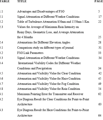
faster internet connectivity is required, Free Space Optics (FSO) has emerged as a promising solution. It is due the advantages of FSO. FSO is the best solution for last-mile bottleneck problem. It offers broader and unlimited bandwidth and license free compare to deployment of microwave link. FSO can be installed in a shorter time and lower cost compare to laying down fiber optic cable [1]. An FSO is an upgraded transmission medium from the fiber optics. For one transmission line, instead of sending the data in a closed glasses path, it is transmitted through the air. Also known as Free Space Photonics (FSP) or Optical Wireless, this transmission line used infrared (IR) beams through the atmosphere to obtain optical communications. FSO works on the same basic principle as Infrared television remote controls, wireless keyboards or wireless Palm devices.
Figure 1.1: A pair of FSO with transceiver in each.
3
connecting buildings. Even though with its disadvantages, FSO could be one of the mainstream wireless systems that will be used in the future.
1.1.1 Comparison between Free Space Optic (FSO) and Fiber Optic Cable (FOC)
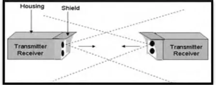
An optical fiber cable is a cable containing one or more optical fibers that are used to carry light. The optical fiber element are typically individually coated with plastic layers and contained in a proactive tube suitable for the environment where the cable will be deployed. Optical fiber consists of a core and cladding layer, selected for total internal reflection due to the different in the refractive index between the two. The light was transmitted between one ends to the other end. The loss of the cable was many due to the scattering inside the fiber cable. Even with the high in cost, fiber optic cable was quite a hit for its fast transmission.
4
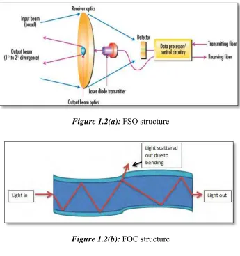
Figure 1.2(a): FSO structure
Figure 1.2(b): FOC structure
1.1.2 FSO History
5
NASA build the system and has providing us with fast communication links in remote locations through various forms.
1.1.3 FSO Advantages, Disadvantages and Market
Telecommunication has seen massive expansion over the last few years. First was the tremendous growth of the optical fiber. Long-haul Wide Area Network (WAN) followed by more recent emphasis on Metropolitan Area Networks (MAN). Meanwhile LAN giga bit Ethernet ports are being deployed with a comparable growth rate. Even then there is pressing demand for speed and high bandwidth. In the United States 5 percent of buildings for the telecommunication industries are connected to OFC. Yet 75 percent are within one mile of fiber. Thus FSO offers to the service providers, a compelling alternative for optical connectivity and a complement to fiber optics. While in Malaysia, investors are not quite familiar with FSO systems. If telecommunication engineers could present the goodness of this system, it could be hits.
Every system has its advantages and disadvantages, including FSO. Below is some of it:
Table 1.1: Advantages and Disadvantages of FSO
Advantage Disadvantage
1) Security system is high 1) Transmitter and receiver have to have line-of-sight to each other.
2) Optical technology and no spectrum licensing or frequency coordination with other users are required.
2) Blocking conditions such as trees, buildings, animals, and atmospheric conditions.
3) Also interference from or to other systems or equipment is not a concern.
3) Sway if installed in tall building.
4) Low cost
6
6) High-speed modulation, small footprint and low power consumption.
1.1.4 FSO Applications
Users demand for high bandwidth and differentiated data services has been one of the crisis thinking to the telecommunication engineer nowadays. An ideas need to be generated in order to maximize the applications of network system and in line with the demand. Network traffic doubles every 9-12 months forcing the bandwidth or data storing capacity to grow and keep pace with this increase. The right solution for the pressing demand is the untapped bandwidth potential of optical communications. Optical communications are in the process of evolving Giga bits/sec to terabits/sec and eventually to pentabits/sec. The explosion of internet and internet based applications has fuelled the bandwidth requirements. Business applications have grown out of the physical boundaries of the enterprise and gone wide area linking remote vendors, suppliers, and customers in a new web of business applications. Hence companies are looking for high bandwidth last mile options. The high initial cost and vast time required for installation in case of OFC speaks for a wireless technology for high bandwidth last mile connectivity there FSO finds its place.
The concept behind FSO is simple. Its uses a directed beam of light radiation between two ends points to transfer information whether it is data, voice or video. The systems were basically similar to the fiber optic cable (FOC) transmission networks, except that light pulses are sent through free air instead of FOC cores. Due to its fast transmission rate, FSO has become quite popular transmission line nowadays. Their application varies, including:
i. Metro Area Network (MAN): FSO network can close the gap between the last
7
ii. Last Mile Access: End users can be connected to high speed links using FSO. It
can also be used to bypass local loop systems to provide business with high speed connections.
iii. Enterprise connectivity: As FSO links can be installed with ease, they provide a
natural method of interconnecting LAN segments that are housed in buildings separated by public streets or other right-of-way property.
iv. Fiber backup: FSO can also be deployed in redundant links to backup fiber in
place of a second fiber link.
v. Backhaul: FSO can be used to carry cellular telephone traffic from antenna towers back to facilities wired into the public switched telephone network.
vi. Service acceleration: Instant services to the customers before fiber being laid.
1.1.5 FSO Working Systems
Figure1.3: How FSO system works
8
taking a standard data, voice or video signal, converting it to a digital format and transmitting it through free space. The beams are kept very narrow to ensure that it does not interfere with other FSO beams. The receive detectors are either PIN diodes or avalanche photodiodes. The FSO transmits invisible eye safe light beams from transmitter to the receiver using low power infrared lasers in the Tera hertz spectrum. FSO can function over kilometers.
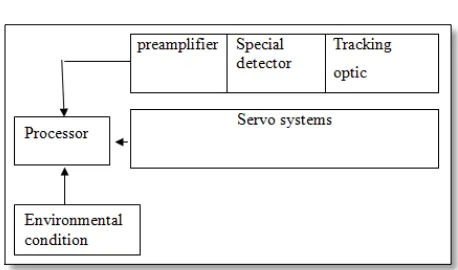
Figure 1.4(a): FSO subsystem
Figure 1.4(b): FSO subsystem (The Processor)