i
CLEANROOM PARAMETERS MONITORING SYSTEMS (CPMS)
MOHAMAD SYAHIR BIN JAPAR
This report is submitted in partial fulfillment of requirement for the Bachelor of Electronic engineering (Industrial Electronics) with Honors
Faculty of Electronics & Computer Engineering University technical Malaysia Melaka
ii
UNIVERSTI TEKNIKAL MALAYSIA MELAKA
FAKULTI KEJURUTERAAN ELEKTRONIK DAN KEJURUTERAAN KOMPUTER
BORANG PENGESAHAN STATUS LAPORAN
PROJEK SARJANA MUDA II
Tajuk Projek : Cleanroom Parameters Monitoring System (CPMS)
Sesi Pengajian : 1 3 / 1 4
Saya MOHAMAD SYAHIR BIN JAPAR
(HURUF BESAR)
mengaku membenarkan Laporan Projek Sarjana Muda ini disimpan di Perpustakaan dengan syarat-syarat kegunaan seperti berikut:
1. Laporan adalah hakmilik Universiti Teknikal Malaysia Melaka.
2. Perpustakaan dibenarkan membuat salinan untuk tujuan pengajian sahaja.
3. Perpustakaan dibenarkan membuat salinan laporan ini sebagai bahan pertukaran antara institusi pengajian tinggi.
4. Sila tandakan ( √ ) :
SULIT*
*(Mengandungi maklumat yang berdarjah keselamatan atau kepentingan Malaysia seperti yang termaktub di dalam AKTA RAHSIA RASMI 1972)
TERHAD** **(Mengandungi maklumat terhad yang telah ditentukan oleh
organisasi/badan di mana penyelidikan dijalankan)
TIDAK TERHAD
Disahkan oleh:
__________________________ ___________________________________
(TANDATANGAN PENULIS) (COP DAN TANDATANGAN PENYELIA)
iii
“I hereby, declare this report is the result of my own research except as cited of the reference”
Signature :
Author Name : MOHAMAD SYAHIR BIN JAPAR
iv
“I / we acknowledge that I have read this piece in my / our this work is sufficient in scope and quality for the award of Bachelor of Electronic Engineering (Industrial
Electronics) With Honors"
Signature : ……….
Name : MUHAMMAD NOORAZLAN SHAH BIN ZAINUDIN
v
vi
ACKNOWLEDGEMENTS
Alhamdullilah, I would like to express my deepest appreciation to my supervisor,
En. Muhammad Noorazlan Shah Bin Zinudin who have helped me making this project possible. His support,guidance and advice throughout this project are greatly appreciated. Indeed without his guidance, i would not complete this project successfully.
In addition, thenks to all my friends that helping me to complete this project and make my dream come. The guidance and support received my friends who are contributing to this project, was vital for the succes of the projects
Finally, first in my heart, I would also like to thanks especially my parents for their continued moral and financial support throughout my studies and project. Without them, I would not to be here and finish my degree.
vii
ABSTRACT
viii
ABSTRAK
ix
TABLE OF CONTENTS
CHAPTER CONTENTS PAGE
PROJECT TITLE i
PROJECT STATUS FORM ii
DECLARATION iii
APPROVAL iv
DEDICATION v
ACKNOWLEDGEMENT vi
ABSTRACT vii
ABSTRAK viii
CONTENTS ix
LIST OF TABLES xii
LIST OF FIGURES xiii
LIST OF ABBREVIATIONS xvi
1.0 INTRODUCTION 1
1.1 Project Overview 1
1.2 Objectives of Project 2
1.3 Problem Statement 3
1.4 Scopes of Work 3
x
1.6 Thesis Outline 4
2.0 LITERATURE REVIEW 5
2.1 Background Study 5
2.2 Software Overview 6
2.2.1 Arduino IDE 6
2.3 Hardware Overview 7
2.3.1 Arduino UNO Rev 3 7
2.3.2 DHT 11 Sensor 8-12
2.3.3 Dust Sensor 13-14
2.3.4 Light Dependent Resistor (LDR) 15-16
2.3.5 Real Time Clock DS 1307 17-18
2.3.6 2.4” TFT LCD Touch Shield 18-19
2.4 Related Project 20-22
2.4.1 Reading DS1820 temperature sensor with PIC16F628A 20 2.4.2 Temperature Alarm Using PIC16C84 Microcontroller 21 2.4.3 Temperature and Humidity Display with Adaptive
Brightness Control Using PIC12F683
22
2.5 Comparison Projects 23
3.0 METHODOLOGY 24
3.1 Project Methodology 24-25
3.2 Data Collection Method 26
3.3 Flow Chart Methodology 27
3.4 Block Diagram 28
3.5 Gantt Chart 29
xi
3.7 Setup an Arduino UNO Board 31-34
3.7.1 USB cable 32
3.7.2 Arduino IDE 33
3.7.3 Arduino Main Board to Computer 34
4.0 RESULT AND DISCUSSION 38
4.1 Overview 38
4.2 Testing The Sensors On Arduiono Board 39
4.2.1 Dust Sensor 39
4.2.2 DHT 11 Sensor 40
4.2.3 LDR Sensor 41
4.2.4 Test The Display 42
4.2.5 Displaying Sensor Data On TFT LCD Shield 43
4.3 Installation 44
4.4 Product Features 45
4.4.1 Sensor supply for Temperature, Humidity, Dew Points, Light Intensity and Dust.
45
4.4.2 Accurate and user friendly. 46-47
4.4.3 Parameter Limit Indicator 48
4.4.4 Large Color Display 48
4.5 FS209E and ISO Cleanroom Standards 49
5.0 CONCLUSION AND RECOMMENDATION 50
5.1 Overview 50
5.2 Project Conclusion 51
xii
REFERENCES 53-54
APPENDICES A 55
APPENDICES B 56
APPENDICES C 57
xiii
LIST OF TABLES
NO TITLE PAGES
1 Table 2.1 : DHT 11 Specifications 9
2 Table 2.2 : Electrical Characteristics for Dust Sensor 14
3 Table 2.3: TFT LCD Specifications 19
4 Table 2.4 : Comparison with others project 23
5 Table 4.1: Accuracy of DHT 11 48
6 Table 4.2: Accuracy of Dust Sensor 48
7 Table 4.3: Sensitivity of LDR sensor 49
xiv
LIST OF FIGURES
NO TITLE PAGES
1 Figure 2.1: Arduino IDE Software 6
2 Figure 2.2: Arduino UNO Rev 3 Main Board 7
3 Figure 2.3: DHT 11 Sensor 8
4 Figure 2.4: Communication Process 11
5 Figure 2.5: Data “0” indication 12
6 Figure 2.6: Data “1” indication 12
7 Figure 2.7: Grove Dust Sensor 13
8 Figure 2.8: Grove Dust Sensor Block diagram 14
9 Figure 2.9: Light Dependant Resistor (LDR) 15
10 Figure 2.10: Resistance versus Luminance Graph 16
11 Figure 2.11: Real Time Clock DS1307 (RTC) 17
12 Figure 2.12: Operating Circuit And Pin Configuration for RTC
DS1307 17
13 Figure 2.13: TFT LCD Touch Shield 18
14 Figure 2.14: Project 1 20
15 Figure 2.15: Project 2 21
xv
17 Figure 3.1: Steps of Methodology 25
18 Figure 3.2: System Flow Chart 27
19 Figure 3.3: Block Diagram 28
20 Figure 3.4: Gantt Chart fpr Semester 1 30
21 Figure 3.5: Arduino UNO Rev.3 31
22 Figure 3.6: USB Cable B Type 32
23 Figure 3.7: Arduino IDE 33
24 Figure 3.8: Found New Hardware 34
25 Figure 3.9: Found New Hardware Wizard 34
26 Figure 3.10: Found New Hardware Wizard 35
27 Figure 3.11: Browse for Folder 35
28 Figure 3.12: Hardware Installation 36
29 Figure 3.13: Found New Hardware Wizard 36
30 Figure 3.14: Device Manager 37
31 Figure 4.1: Dust Sensor Result on Serial Monitor 39
32 Figure 4.2: DHT 11 Result on Serial Monitor 40
33 Figure 4.3: LDR Result on Serial Monitor 41
34 Figure 4.4: Testing LCD Display 42
35 Figure 4.5: Displaying Sensor Data on LCD 43
36 Figure 4.6: Assembling Cleanroom Parameters Monitoring System
(CPMS) 44
37 Figure 4.7: DHT 11 Parameters 45
38 Figure 4.8: LDR Parameter 45
39 Figure 4.9: Particle Count Parameter 46
40 Figure 4.9: Resistance as Function of Illumination 47
41 Figure 4.10: Limit Indicator for Parameters 48
xvi
LIST OF ABBREVIATIONS
CPMS - Cleanroom Parameter Monitoring System OTP - One Time Programmable
TFT - Thin Film Transistor
ICSP - In Circuit Serial Programming
FTDI - Future Technology Devices International USB - Universal Serial Bus
DC - Direct Current
1
CHAPTER I
INTRODUCTION
1.1 Project Overview
2
1.2 Objectives of Project
The specific objectives of this project are to:
1. Monitor the actual parameters of clean room environment. 2. Alerts the conditions that exceeding classification.
The first objective is to monitor and analyze the actual parameter of cleanroom environment. By using DHT 11 (temperature & humidity sensor) and air contaminant sensor environment inside the cleanroom can be monitor and will be display out on the TFT LCD color display. The he data of the temperature, humidity, dew points and dust can be monitor and analyze every hour by the employee. The reasons why the cleanroom should be monitor is to verify either the process environment is perform according to the requires specifications because this areas are built to the specific requirements of the product that to be built.
3
1.3 Problem Statement
The purpose of this project is to monitor the quality of environment in clean room area where the products are manufactured which the concentration of airborne particles is controlled to the specified limits. The contaminants inside the clean room are produced by the people, process, facilities and equipment.
The way to control the contamination is by control the overall environment inside that area where temperature, humidity, dew points,light intensity and dust need to be tightly controlled. In this project, it will show the current value of temperature, humidity, dew points, dust and light intensity.
1.4 Scopes of Work
The scopes of works in this project are:
1. The design of this CPMS is to minimal the device for portable user inside the clean room area.
2. The implemented of CPMS will consists of totally 3 sensor in 1 device which are humidity and temperature sensor, air contaminant sensor , dew points and light intensity sensor.
3. The coding software that will be used for this project is Arduino.
1.5 Project Planning
4
1.6 Thesis Outline
This thesis report contains 5 chapters that will explain more details on each chapter to give an understanding about the whole project.
Chapter one will explain detail on the introduction of this project. In this chapter, it presents an overview of quality environment for the cleanroom, objective project, scope of works and project planning.
Chapter two will covers more about the literature review on the software and hardware that will be used in this project. This chapter will discuss about the source and article that related to this project. It will also relate the theory of components and programming language by using Arduino Uno Rev.3. So this is important to understand more about the overall concepts.
Chapter three will explain more about the project methodology, project planning and project finishing. It will show the progress of this project according to the due date which had been set before the project is in progress. In this chapter also will include the flow chart and block diagram that will explain more about the project system and it will also include Gantt chart for Semester I and II.
Chapter four is about the result and discussion for final year project. In this chapter it will show how to set up the arduino software connect with Windows and installation of arduino libraries. Other than that, this chapter will discuss about how to troubleshoot the problems if anything happen to the software and hardware.
5
CHAPTER II
LITERATURE REVIEW
2.1 Background Study
6
[image:22.612.255.402.134.242.2]2.2 Software Overview 2.2.1 Arduino IDE
Figure 2.1: Arduino IDE Software
7
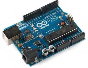
[image:23.612.261.432.165.297.2]2.3 Hardware Overview 2.3.1 Arduino UNO Rev.3
Figure 2.2: Arduino UNO Rev 3 Main Board
8
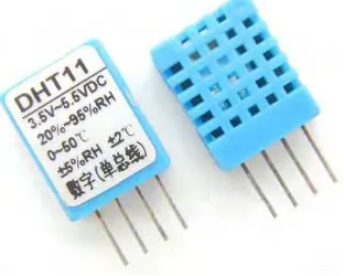
[image:24.612.268.424.137.262.2]2.3.2 DHT 11 Sensor
Figure 2.3: DHT 11 Sensor
DHT 11 is the sensor used for this project. This sensor will display the current parameters for temperature, humidity and dew points where the sensor complex are calibrated with digital signal output[2]. To ensures high reliability and long term stability, this sensor is using exclusive digital signal acquisition technique and sensing technology. It consists of resistive type humidity measurement component and NTC temperature component. This sensors is connected with high performance of 8 bit microcontroller that offering excellent quality, cost effectiveness, fast response and anti interference ability.