FATIGUE ANALYSIS OF STEERING KNUCKLE
AMMER EZHAR B MOHD RAZALLI (B041110209)
This thesis is submitted in fulfillment of the requirements for the degree of Bachelor Degree of Mechanical Engineering (Design and Innovation)
Fakulti Kejuruteraan Mekanikal Universiti Teknikal Malaysia Melaka
i
SUPERVISOR DECLARATION
“I hereby declare that I have read this thesis and in my opinion this thesis is sufficient in terms of scope and quality for the award of the degree of
Bachelor of Mechanical Engineering (Design & Innovation)”
ii
DECLARATION
“I hereby declare that the work in this thesis entitle Fatigue Analysis of Steering Knuckle
is my own except for summaries and quotations which have been duly acknowledged.”
Signature : ...
Author : AMMER EZHAR B MOHD RAZALLI
iii
iv
ACKNOWLEDGEMENTS
Praise to Allah almighty for giving me that strength and chance to complete my thesis. The special gratitude go to my constructive supervisor, Dr. Kamarul Ariffin bin Zakaria for providing me an excellent advice, full support and encouragement in doing this project.
The co-operation is significantly indeed appreciated. I have taken hard work in this project. However, it would not have been achievable without the generous support and help of numerous individuals in particular and the faculty as well. I would like to extend my sincere thanks to every one of them.
Apart from that, I would like to express my gratitude towards my parents & lecturers for their kind co-operation and support which help me in finishing of this project. Parallel thereby, my innermost gratitude to the panel for contributes in finishing this project.
v
ABSTRACT
vi
ABSTRAK
vii
CONTENTS
CHAPTER TITLE PAGES
SUPERVISOR DECLARATION i
DECLARATION ii
DEDICATION iii
ACKNOWLEDGEMENT iv
ABSTRACT v
ABSTRAK vi
CONTENT vii
LIST OF TABLE x
LIST OF FIGURE xi
LIST OF ABBREVIATION xiii LIST OF APPENDICES xiv
CHAPTER I INTRODUCTION
1.1 Background study 1
1.2 Problem statement 2
1.3 Objective 2
1.4 Scope 2
CHAPTER II LITERATURE REVIEW
2.1 Introduction 4
2.2 Fatigue life 5
2.2.1 Introduction to fatigue life 5 2.2.2 Factor affecting fatigue life 6
2.3 Car suspension system 7
2.3.1 Introduction 8
2.3.2 Type of suspension system 8
viii
2.3.2.2 Swing axle suspension 9 2.3.2.3 Trailing link suspension 9
2.3.2.4 Strut suspension 10
2.3.2.5 Short/long arm suspension 11 2.4 Manufacturing process of steering knuckle 12
2.4.1 Research on material 13
2.5 Finite element analysis 14
2.5.1 Introduction to FEA 14
2.5.2 Comparison of finite element analysis
with other method 15
2.5.3 Application of FEA 16
CHAPTER III METHODOLOGY
3.1 Introduction 18
3.2 Flow chart for PSM 1 18
3.3 Finding information 19
3.4 Part selection 20
3.5 Dimensioning and geometry 21
3.6 CAD drawing 23
3.7 Flow chart for PSM 2 23
3.8 Data selection process for analysis 24
3.9 Analysis of steering knuckle 26
CHAPTER VI RESULTS AND DISCUSSION
4.1 Static and fatigue results 32
4.1.1 Results for first test 33
4.1.2 Results for second test 35
4.1.3 Results for third test 38
4.1.4 Results for fourth test 41
4.1.5 Results for fifth test 44
ix
CHAPTER V CONCLUSION AND RECOMMENDATION
5.1 Conclusion 50
5.2 Recommendation 51
REFERENCES 53
APPENDIX A 55
x
LIST OF TABLES
NO. TITLE PAGE
2.1 Effect of surface roughness on fatigue life 7
3.1 Force acting on knuckle 25
3.2 Material properties for grey cast iron 27
xi
LIST OF FIGURES
NO. TITLE PAGE
2.1 Steering knuckle system 5
2.2 Beam axle design 8
2.3 Swing axle suspension 9
2.4 Trailing link suspension 10
2.5 MacPherson suspension system 11
2.6 SLA suspension system 12
2.7 S-N curve for the three material 13
2.8 Different type of solution 16
2.9 FEA for the engine block 17
2.10 FEA for cast ceramic 17
3.1 Flow chart for PSM 1 19
3.2 Perodua Myvi knuckle 21
3.3 3D scanner workplace 22
3.4 Images generated 22
3.5 CAD drawing for knuckle 23
3.6 Flow chart for PSM 2 24
3.7 Location of forces 26
3.8 SolidWorks Simulation for static analysis 28
3.9 Applying material to steering knuckle 29
3.10 The interface for fatigue 30
3.11 The S-N curve for grey cast iron 30
3.12 Static analysis overview 31
3.13 Fatigue analysis overview 31
4.1 Von mises stress for first test 33
4.2 Displacement for first test 34
xii
4.4 Damage percentage for first test 35
4.5 Life plot for first test 35
4.6 Von mises stress for second test 36
4.7 Displacement for second test 36
4.8 Factor of safety for the second test 37
4.9 Damage percentage for second test 38
4.10 Life plot for second test 38
4.11 Von mises stress for third test 39
4.12 Displacement for third test 39
4.13 Factor of safety for third test 40
4.14 Damage percentage of third test 40
4.15 Life plot for third test 41
4.16 Von mises stress for fourth test 42
4.17 Displacement for fourth test 42
4.18 Factor of safety for fourth test 43
4.19 Damage percentage for fourth test 43
4.20 Life plot for fourth test 44
4.21 Von mises stress for fifth test 44
4.22 Displacement for fifth test 45
4.23 Factor of safety for fifth test 45
4.24 Damage percentage for fifth test 46
xiii
LIST OF ABBREVIATIONS
DVVT - Dynamic Variable Valve Timing CAD - Computer Aided Drawing
CATIA - Computer Aided Three Dimensional Interactive Application FEA - Finite Element Analysis
PSM - Projek Sarjana Muda PSB - Prolonged Sip Band
xiv
LIST OF APPENDICES
NO. TITLE PAGE
A1 Gantt chart for PSM 1 56
A2 Gantt chart for PSM 2 57
B1 Knuckle image 1 59
B2 Knuckle image 2 59
1
CHAPTER 1
INTRODUCTION
1.1 BACKGROUND STUDY
Nowadays, the automobile industry becomes one of the assets for economic development. The automobile industry has grown rapidly since the production of the first car by Henry Ford. Cars have been improved dramatically from year to year in term of design, safety, technology and also performance. Steering module which related to handling is a piece of automobile suspension system which related to an exact vehicle stability and position. Steering knuckle is one of the automotive part on car and specifically been used in suspension system. The steering knuckle functions is to allow the wheels to turn. On cars with conventional suspension frameworks, the steering knuckle includes a spindle and connects the lower and upper ball joints. For modern cars which use MacPherson strut suspension systems, the steering knuckle connects the strut assembly to the lower ball joint.
2
knuckle, the right application should be consider and the analysis on reliability of the steering knuckle must be done. For future recommendation, this research need to analysed and study the fatigue life for various type and structure of steering knuckle.
1.2 PROBLEM STATEMENT
In today automobile vehicle, speed and handling plays an important factor in car construction. Because of this, steering knuckle need to have higher strength and stiffness but also must be lighter in weight and also size. In developing power output vehicle, the important goes to how to place the exact weight of linier and angular parts in steering knuckle. The overall performance of steering knuckle is affected by higher inertia force especially during driving which generated by the moving parts in the vehicle. This inertia comes from the uneven forces that act on the steering knuckle which can affect the lifetime and also the performance itself. Besides that, waste on material can also occur due to lack of knowledge and study in stress distribution on steering knuckle. Thus, an investigation on steering knuckle needs to be done In order to prevent any failure which can affect the car performance.
1.3 OBJECTIVE
The objective for this project are:
I. To apply 3D CAD modelling and Finite Element Analysis on steering knuckle. II. To investigate the fatigue life behaviour of steering knuckle under various
loading conditions.
1.4 SCOPES
There are several lists of scopes which will be applied thorough out the project. The scopes are:
3
II. To analysed effect of acting force in steering knuckle using Finite Element Analysis.
III. To use SolidWorks Simulation as the simulation software to analysed fatigue failure.
IV. To identify the minimum stress area in steering knuckle.
4
CHAPTER 2
LITERATURE REVIEW
2.1 INTRODUCTION
In today manufacturing industry, the detail and specifications of steering knuckle comes in various design and shape for automobile vehicles. The configuration incorporates the specification vehicle whether it is suit or not with the vehicle itself. In addition, the design also emphasize the of reliability component whether the part can oblige the force that subjected on it. Although there are plenty of steering knuckle in the market today, the most important problem that occur in all automobile industry is the durability and reliability of the knuckle itself. Because of this problem, the understanding on stress and strain analysis and principle which experienced by the steering knuckle is needed in order to overcome the problem.
5
brake and the calliper. For Double Wishbone the knuckle is placed between upper and lower ball joints, while for MacPherson strut the lower ball joint with the strut itself.
Figure 2.1: Steering knuckle system (Source: Azrulhisham et. al, 2010)
2.2 FATIGUE LIFE
2.2.1 Introduction to Fatigue Life
6
probably result in increased local stresses in which fatigue cracks can initiate while circular holes and smooth transitions or fillets will therefore raise the fatigue strength of the structure (Kim & Laird, 1978).
Fatigue life can be divided into four stages before the material begin to failure. The first stage is the crack initiation features the beginning of growth and development of fatigue damage that could be eliminated by an effective thermal anneal. Secondly, slip-band crack enhancement includes the deepening of the primary crack on planes of higher shear stress. This normally is known as stage one crack growth. Thirdly, crack growth on planes of higher tensile stress includes growing of distinct crack in direction normal to maximum tensile stress. Commonly known as stage two crack growth. Ultimate ductile failure happens when the crack actually gets to adequate length as a result the remaining cross section are unable to support the applied load.
2.2.2 Factor Affecting Fatigue Life
7
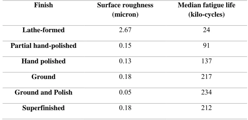
Table 2.1: Effect of surface roughness on fatigue life
Finish Surface roughness (micron)
Median fatigue life (kilo-cycles)
Lathe-formed 2.67 24
Partial hand-polished 0.15 91
Hand polished 0.13 137
Ground 0.18 217
Ground and Polish 0.05 234
Superfinished 0.18 212
(Source: eFunda, 2014)
2.3 CAR SUSPENSION SYSTEM
There are many types of car suspension system. The most common one is the MacPherson strut suspension system. It can be seen on many cars on the road. Different types of suspension system give different experiences in term of handling. This is because some vehicles are made for racing, daily drive and many more.
2.3.1 Introduction
8
2.3.2 Type of Suspension System
The suspension system have many design in which give different driving experience to the driver. However, all the suspension system are related to each other and provide the same function to the vehicle.
2.3.2.1 Solid Beam Axle
Getting into chronological order, the very first mass produced front part suspension design and style was the solid beam axle. In the same way that it looks, in the beam axle setup the two of the front wheels are linked to each other by a solid axle (Isaac-Lowry, 2004) as shown in figure 2.2. This design was brought over to the first automobiles from the horse driven carriages of earlier times and worked adequate to ensure that in the beginning no other suspension even necessary to be considered (Isaac-Lowry, 2004). As a matter of fact the beam axle can certainly still be discovered these days. New improvements in springs, roll bars, and shocks have kept the solid axle convenient for certain applications. This design continue used on semi-trucks as well as the large trucks due to the strength of the axle (Kilchermann, 2015).
9
2.3.2.2 Swing Axle Suspension
After designers had recognized the significant downsides of the solid axle front suspension, they proceed forward to create an initiative independent design of front suspension. One of those design is the swing axle suspension which is shown in figure 2.3. It is, as the term indicates, set up so that the axles pivot around a location at some place near the center of the vehicle and enable the tires to travel up and down throughout their specific arcs (Isaac-Lowry, 2004). This design was used by some sports car in the 50s such as the Mercedes 300SL Gullwing. However, the problem raised when applying this suspension is the unloading of the tires after encountering a bump in the road (Kilchermann, 2015). Soon, designers add a universal joint between the axle and the wheel which allowed the wheel to remain at its position whenever hit a bump.
Figure 2.3: Swing axle suspension (Sources: Isaac-Lowry, 2004)
2.3.2.3 Trailing Link Suspension