Fatigue Strain Signal Behaviour and Damage Assessment of
an Engine Mount Bracket
K A Zakaria1,2*, S Abdullah1, M J Ghazali1, M Z Nuawi1, S M Beden1 and Z M Nopiah1
1Department of Mechanical and Materials Engineering, Universiti Kebangsaan Malaysia, 43600 UKM Bangi, Selangor, Malaysia 2Department of Structure and Materials, Faculty of Mechanical Engineering, Universiti Teknikal Malaysia Melaka, Hang Tuah Jaya,
76100 Durian Tunggal, Melaka, Malaysia
Received 20 July 2012; revised 04 February 2013; accepted 04 October 2013
This paper discusses the fatigue strain signal behaviour of different road surface conditions and its relationship to the fatigue damage of an engine mount bracket. Two different sets of fatigue strain signals were obtained from an engine mount bracket of an automobile: when the automobile was driven on a highway surface and on a residential area road surface. The behaviour of the strain signal was then analysed and classified using both statistical and signal processing tools. Damage values as a result of the corresponding fatigue strain signals also determined using commercial finite element software. The fatigue strain signal behaviour was influenced by the road surface conditions, which affected the damage to the engine mount bracket. The integrated kurtosis-based algorithm for the Z-filter and power spectral density calculation were found to be the most suitable signal analysis approaches to correlate the fatigue strain signal behaviour with the engine mount bracket damage.
Keywords: Fatigue damage, strain signal, variable amplitude loading
Introduction
In the automotive and manufacturing industry, the fatigue damage assessment of a mechanical component is an important design stage. In service, the vast majority of structures and components are subjected to variable amplitude stresses. The failure of the component under variable amplitude loading (VAL) condition is a complex phenomenon and is difficult to assess, particularly due to the load interactions1. A significant acceleration or retardation in the crack growth process can occur as a result of this type of load interactions. Tensile overloads in cycle’s retarded and compressive underloads accelerated the fatigue crack growth rates2-3. Thus, it is of great importance to understand the fatigue and failure mechanisms associated with VAL to quantify fatigue damage4.
An engine mount bracket is an automobile component that connects the engine block to the vehicle structure, whose primary function is to support the weight of the engine and to ensure the engine can be freely maintained in its specified design position5. The engine mount bracket is directly
exposed to static loads and unbalanced forces from the engine. The road surface condition is one of the factors that contribute to the unbalanced forces. For the vehicle body structure, the durability assessment has traditionally been performed at the later stage when prototypes are available. Because of the development of computer-aided engineering tools, finite element analysis and fatigue life prediction is now widely used today in the early stages of evaluating product durability6.
The strain-based approach in fatigue problems is widely used because strain can be measured and provides an excellent correlation with low-cycle fatigue. Fatigue strain signals are normally measured using a strain gauge and recorded in the form of a time series signal. Statistical methods have been extensively used in processing real-world signals7. The behaviour of signals can be classified using statistical or signal processing tools. However, current global signal statistical analysis is only sensitive to amplitude or frequency signals.
The purpose of this paper was to investigate the fatigue strain signal behaviour and relate it to the road surface conditions using statistical and signal processing techniques and identify the best approach
_________
to correlate the conditions with the fatigue damage of an engine mount bracket. It was expected that the fatigue strain signal behaviour and engine mount bracket damage are influenced significantly by the road surface condition. The most suitable signal analysis approach that described the fatigue strain signal behaviour related to the engine mount bracket damage was then identified.
Methodology
Aluminium alloys have been widely used in automotive and airplane parts because of their light weight, excellent weldability and corrosion resistance8-9. The aluminium alloy, Al6061-T6, was selected for our simulation purpose due to its acceptable mechanical properties coupled with its relative ease with which it can be cast, extruded, rolled, machined, etc., its market acceptance and its relative ease of development10. The chemical composition11 and mechanical properties12 of this material are shown in Tables 1 and 2, respectively. The strain-life method has been widely used in fatigue life analysis. The strain-life concept is based on the assumption that fatigue cracks are initiated by local strains and stresses on the surface of the component13. Strain can be measured and has been shown to correlate well with low-cycle fatigue14 and is attractive for practical fatigue investigations where strain signals can be measured using strain gauges. Three different fatigue damage models12: Coffin-Manson, Smith-Watson-Topper (SWT) and Morrow were used in the analysis.
In this study, fatigue strain signals were collected from an engine mount bracket of a 1300 cc automobile. The position of the strain gauge was chosen based on the most critical area determined by the finite element analysis, which was performed prior to testing. From static finite element analysis, the highest stress/strain occurred around the pin hole of bracket and it was chosen to fix the strain gauge for collecting fatigue strain signal. The gauge length of the strain gauge used in this study was 2.0 mm with a resistance of 120 , which was a suitable size to fix on the limited space of the engine mount bracket. The data were measured using a fatigue data acquisition
system that connected to the strain gauge and a computer. A study by Slobodan15 found that the sampling frequency for fatigue data collection should be more than 400 Hz. Lower sampling frequency may produce higher error for fatigue data analysis. In this study, the sampling rate of 500 Hz was chosen because it was used widely in capturing fatigue strain signal of automotive components16-17, and to get an adequate number of data to improve the accuracy18. The automobile was driven on two different road surfaces: a residential area surface and a highway road at essentially a constant velocity of 15-25 km/hr and 80-90 km/hr, respectively. These velocities are the approximate speed for most automobiles on the respective road and were stable for capturing the strain data signals19. The highway road is a good, smooth surface condition, whereas the residential area road surface was slightly rough with small pit holes and bumps along the road.
The fatigue life can be estimated for every element in the finite element model, and a damage contour plot can be obtained6. A three-dimensional engine mount bracket was drawn using CATIA software. The model was then exported to commercial finite element software as a finite element model, where the required properties, such as material properties, applied loading and constraint information, were defined. The mesh model was constructed using 10-node tetrahedron elements. Tetrahedral meshing produces high-quality meshing for boundary representation of a
Table 1—Typical chemical composition of Al6061-T6
Element Mg Si Cu Mn Fe Cr Al
Weight [%] 0.8-1.2 0.4-0.8 0.15-0.40 0.15 0.7 0.04-0.35 bal. Table 2—Mechanical properties of Al6061-T6
Properties Al6061-T6
Monotonic Properties
Ultimate tensile strength, Su(MPa) 314
Yield strength, YS (MPa) 289 Modulus of elasticity, E (GPa) 69.6 Strength coefficient, K (MPa) 416 Strain hardening exponent, n 0.079 Cyclic and Fatigue Properties
Fatigue strength coefficient, f’ (MPa) 535
Fatigue strength exponent, b -0.082 Fatigue ductility coefficient, f’ 1.34
solid model imported from computer-aided design systems. The TET10 mesh can give a more accurate solution if 10-node elements are used in the analysis18.
Results and Discussion
Variable amplitude strain signals were sampled at 500 Hz with a 72-second recording length (refer Fig. 1), producing 36,000 data points for both road conditions. The strain signal of the highway road fluctuated more steadily with a total strain range of 107 ε, whereas the strain signal of the residential area road fluctuated more rapidly with a total strain range of 191.79 ε. The maximum and minimum strain values for the highway road signal were 46.76 ε and -60.24 ε, respectively, compared with the values of the residential area road surface at 97.53
ε and -94.26 ε, respectively. The higher strain range of the residential area road indicates that the engine mount bracket experienced a greater displacement when the automobile was driven over the residential area road surface compared with the highway road surface. The magnitude of displacement or elongation at a specified, localised area on the bracket was measured by the strain gauge in the form
of a time series history. Higher peaks on the fatigue strain signal may indicate the physical condition of the road surfaces, such as the presence of pit holes and road bumps that cause the engine to move up and down more frequently in this area.
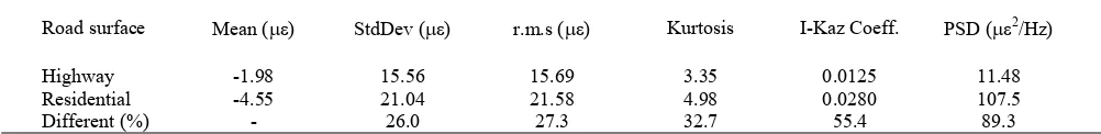
Table 3 summarises the characteristic values of the highway and residential area road strain signals. The results indicated that the fatigue strain signal from the highway road had a mean value of -1.98 ε, a standard deviation of 15.56 ε and an r.m.s value of 15.69 ε. The fatigue strain signal from the residential area road signal had a mean value of -4.55 ε, a standard deviation of 21.04 ε and an r.m.s. value of 21.58 ε. The standard deviation and r.m.s. values were higher in the residential area road strain signal compared with that of the highway road strain signal, which indicates that the strain signals were more spread out with higher energy contents.
The kurtosis is used to measure the peak of the probability distribution of a real-valued random variable. The residential area road strain signal showed a higher kurtosis compared with the highway road strain signal with values of 4.98 ε and 3.35 ε, respectively. A higher kurtosis means most of the variance is the result of infrequent, extreme deviations and is indicative of the presence of more extreme values than what is found in a Gaussian distribution9. The I-kaz method is an analysis method that uses the concept of data distribution around the centroid point of the data and provides a three-dimensional graphical frequency distribution of the measured signals and the I-kaz coefficient20. The graphical representation19 shows a larger data scatter for the residential area road strain signals compared with that of the highway road. The I-kaz coefficients for both types of fatigue strain signals were 0.0280 and 0.0125, respectively. This finding suggests that the residential area road loading, which exhibited larger strain range amplitudes, produces a larger data scatter and larger I-kaz coefficients.
A power spectra density (PSD) is a normalised density plot describing the mean square amplitude of each sinusoidal wave with respect to its frequency.
Table 3—Characteristic values of strain signals
Road surface Mean (ε) StdDev (ε) r.m.s (ε) Kurtosis I-Kaz Coeff. PSD (ε2/Hz)
Highway -1.98 15.56 15.69 3.35 0.0125 11.48
Residential -4.55 21.04 21.58 4.98 0.0280 107.5
Different (%) - 26.0 27.3 32.7 55.4 89.3
The PSD plot for the highway road strain signal has an effective frequency range from 0 to 15 Hz with a maximum PSD value of 11.48 2/Hz. The PSD plot for the residential area road signal has an effective frequency range from 0 to 5 Hz with a maximum PSD value of 107.5 2/Hz. Both results show that frequency dominates at the lower frequency range, which is related to the load of component. In addition, the higher PSD value indicates that there was more vibrational energy21, in the residential area road strain signal compared with that in the highway road strain signal.
From signal analysis, the signal behaviour can be identified and could differentiate between the fatigue strain signal of a highway and residential area road. The largest difference between the two signals would be the most sensitive signal analysis approach and can be represented in term of a percentage difference. The I-kaz and PSD results in a higher percentage difference compared with the other strain signal analysis approach. These two analyses are more sensitive to the changes in the fatigue strain signals amplitude. In other words, small changes in the strain signal amplitude are easier to detect by these approaches.
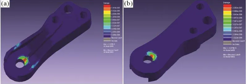
Fig. 2 shows the plots of the localised fatigue damage contour of the engine mount bracket subjected to a strain signal from the residential area road. From the results, it can be seen that the most critical area is around the pin hole of the bracket. The fatigue damage values for each strain life model were analysed from the finite element analysis. The results showed that the fatigue damage values for residential area road loading was greater than 50% than that of the highway road loading for all damage model types. The SWT model resulted in the greatest fatigue damage value of 7.90 × 10⁻⁵ block cycles for the
residential area road and 2.42 × 10⁻⁷ block cycles for the highway road. The Coffin-Manson-Basquin model gave damage values of 4.88 × 10⁻⁵ block cycles and 6.11 × 10⁻⁸ block cycles, and the Morrow model gave damage values of 4.81x10⁻⁵ block cycles and 9.44 × 10⁻⁷ block cycles for the two types of loading, respectively. The SWT model is more accurate for brittle material, such as cast iron and aluminium alloys13. In the SWT model, the fatigue life is a function of the strain amplitude and the maximum stress in the cycle. The maximum stress is obtained for each closed hysteresis loop.
Fig. 3 plots the I-kaz coefficient and PSD scatters with the total fatigue damage for each strain-life model. There are two groups of scatter in the plot, which is a result of the two different fatigue strain signals. Group 1 is represented by a smaller I-kaz coefficient and PSD values in the lower region of fatigue damage, whereas group 2 is represented by a larger I-kaz coefficient and PSD values in the higher region of fatigue damage. A larger I-kaz coefficient indicates greater amplitude and frequency changes, and larger PSD values indicate more vibrational
Fig. 2 – Fatigue damage contour that indicates the critical point for crack initiation on the engine mount bracket: (a) front and (b) bottom view
energy in the strain signal. The findings showed that the higher strain range will give a larger I-kaz coefficient and PSD value, which will mean greater damage to the engine mount bracket. Therefore, the total fatigue damage of an engine mount bracket increases as the I-kaz coefficient and PSD value of the strain signal increases.
Conclusion
The paper analysed the fatigue strain signals of an engine mount bracket using various signal analysis approaches and found consistence results showing that the fatigue strain signal behaviour is influenced significantly by the road surface conditions. Statistical and signal behaviour values, such as the r.ms., kurtosis, I-kaz coefficient and PSD, were found to be greater for the residential area road strain signals compared with those from the highway road strain signals, which was related to a higher strain signal energy. Moreover, the I-kaz and PSD approach showed a greater reflection of the fatigue strain signal behaviour compared with the other signal analysis approaches.
The engine mount bracket, which is an important component in an automobile engine, must be reliable for all road surface conditions. The damage values of the bracket showed significantly more damage when subjected to the residential area road strain signals compared with the highway road strain signal for all three fatigue strain-life models. Because a close relationship exists between the fatigue strain signals, the signal behaviour values and the fatigue damage of an engine mount bracket, it was suggested that the engine mount bracket damage can be directly monitored by the behaviour of the fatigue strain signals.
References
1 Carvalho A L M, Martins J P & Voorlwood H J C, Fatigue damage accumulation in aluminium 7050-T7451 alloy subjected to block program loading under step-down sequence, Proc Eng, 2 (2010) 2037-2043.
2 Schijve J, Skorupa M, Skorupa A, Machniewicz T & Grusczynski P, Fatigue crack growth in the aluminium alloy D16 under constant and variable amplitude loading, Int J Fatigue, 26 (2004) 1-15.
3 Daneshpour S, Koçak M, Langlade S & Horstmann M, Effect of overload on fatigue crack retardation of aerospace al-alloy laser welds using crack-tip plasticity analysis. Int J Fatigue, 31 (2009) 1603-1612.
4 Wei L W, de los Rios E R & James M N, Experimental study on modelling of short fatigue crack growth in aluminium alloy A17010-T7451 under random loading, Int J Fatigue, 24 (2001) 963-975.
5 Yu Y, Naganathan N G & Dukkipati R V, A literature review of automotive vehicle engine mounting systems, Mech Machine Theor, 36 (2001) 123-142.
6 Rahman M M, Ariffin A K, Jamaludin N & Haron C H C, Durability assessment of a new free piston spark ignition linear engine: a computational approach, J Teknologi, 45A (2006) 81-102.
7 Nuawi M Z, Abdullah S, Ismail A R, Zulkifli R, Zakaria M K & Hussin MFH, A study on ultrasonic signals processing generated from automotive engine block using statistical analysis, WSEAS Tran on Sig Proc, 4 (2008) 279-288.
8 Feng M D, Qiu H G, Fei H Z, Yu Z Z, Shu C C & Hua Z W, Crack initiation and propagation of cast A356 aluminium alloy under multi-axial cyclic loadings, Int J Fatigue, 30 (2008) 1843-1850.
9 Gao G L, Shi D Q, Li D Y, Dong J W & Shi X D, Experimental study on fatigue crack identification of 7075 aluminium alloy plate using combination NEWMS and TRA, Ind J Eng & Mater Sci, 18 (2011) 377-380.
10 Jogi B F, Brahmankar P K, Nandar V S & Prasad R C, Some studies on fatigue crack growth rate of aluminium alloy 6061, J Mater Proc Tech, 201 (2008) 380-384.
11 Boyer H E & Gall T L (Eds.), Metal Handbook Desk edition (American Society for Metal, Metal Park Ohio) 1985 12 ICE-flow® analysis DesignLifeTM 5.1. nCode Material
Database, nCode International Ltd.Shefield.
13 Draper J, Modern metal fatigue analysis (Emas Publishing Ltd, United Kingdom) 2007
14 Stephens R I, Fatemi A, Stephens R R & Fuchs H O, Metal Fatigue In Engineering, Second edition (John Wiley & Sons, New York) 2001.
15 Slobodan I, Methodology of evaluation of in-service load applied to the output shaft of automatic transmission, PhD Thesis, The University of New South Wales, 2006. 16 Haiba M, Barton D C, Brooks P C & Levesley M C, The
development of an optimisation algorithm based on fatigue life, Int J Fatigue, 25 (2003) 299-310.
17 He B, Wanga S, Gao F, Failure analysis of an automobile damper spring tower, Eng Fail Anal, 17 (2010) 498-505. 18 Kadhim N A, Abdullah S, & Ariffin A K, Effect of fatigue
data editing technique associated with finite element analysis on the component fatigue design period, Mater & Design, 32 (2011) 1020-1030.
19 Zakaria K A, Abdullah S, Ghazali M J, Nuawi M Z & Padzi M M, Fatigue damage assessment of the engine mount bracket using a statistical based approach, Adv Mater Research, 197-198 (2011) 1631-1635.
20 Nuawi M Z, Pembangunan system pemantauan keadaan perkakas mesin menggunakan kaedah isyarat ultrasonic bawaan udara, PhD Thesis, Universiti Kebangsaan Malaysia, 2008.