UNIVERSITI TEKNIKAL MALAYSIA MELAKA
DESIGN AND SIMULATION OF IN-PIPE GENERATOR
This report is submitted in accordance with the requirement of the Universiti Teknikal Malaysia Melaka (UTeM) for the Bachelor of Electrical Engineering
Technology (Industrial Power) with Honours
by
HANISAH NADIAH BINTI A.JALIL
B071210239
900209-01-6630
UNIVERSITI TEKNIKAL MALAYSIA MELAKA
BORANG PENGESAHAN STATUS LAPORAN PROJEK SARJANA MUDA
TAJUK: DESIGN AND SIMULATION OF IN-PIPE GENERATOR
SESI PENGAJIAN: 2015/16 Semester 1
Saya HANISAH NADIAH BINTI A.JALIL
mengaku membenarkan Laporan PSM ini disimpan di Perpustakaan Universiti Teknikal Malaysia Melaka (UTeM) dengan syarat-syarat kegunaan seperti berikut:
1. Laporan PSM adalah hak milik Universiti Teknikal Malaysia Melaka dan penulis. 2. Perpustakaan Universiti Teknikal Malaysia Melaka dibenarkan membuat salinan
untuk tujuan pengajian sahaja dengan izin penulis.
3. Perpustakaan dibenarkan membuat salinan laporan PSM ini sebagai bahan pertukaran antara institusi pengajian tinggi.
4. **Sila tandakan ( )
SULIT
TERHAD
TIDAK TERHAD
(Mengandungi maklumat yang berdarjah keselamatan atau kepentingan Malaysia sebagaimana yang termaktub dalam AKTA RAHSIA RASMI 1972)
(Mengandungi maklumat TERHAD yang telah ditentukan oleh organisasi/badan di mana penyelidikan dijalankan)
(TANDATANGAN PENULIS)
iv
DECLARATION
I hereby, declared this report entitled “DESIGN AND SIMULATION OF IN-PIPE
GENERATOR” is the results of my own research except as cited in references.
Signature :………
Name : HANISAH NADIAH BINTI A.JALIL
v
APPROVAL
This report is submitted to the Faculty of Engineering Technology of UTeM as a partial fulfilment of the requirements for the degree of Bachelor of Electrical Engineering Technology (Industrial Power) with Honours. The member of the
supervisory is as follow:
……….
vi
ABSTRACT
vii
ABSTRAK
viii
DEDICATIONS
ix
ACKNOWLEDGMENTS
x
LIST OF SYMBOLS AND ABBREVIATIONS ... xvi
CHAPTER 1 ... 1
2.2 The potential Hydropower in Malaysia ... 4
2.3 Hydropower ... 4
xi
2.4 Small Hydro ... 6
2.5 Run of River plant ... 7
2.6 Synchronous Motor ... 9
2.7 Permanent Magnet Synchronous Motor (PMSM) ... 10
2.7.1 The Speed Control of Permanent Magnet Synchronous Motor ... 11
2.8 ANSYS Maxwell Software ... 13
2.9 General Design Parameter ... 14
CHAPTER 3 ... 17
3.1 Introduction ... 17
3.2 Methodology of the Project ... 17
3.2.1 Literature Review ... 19
3.2.2 Design Generator ... 19
3.2.3 Simulation ... 20
3.2.4 Evaluate the result ... 20
3.2.5 Writing Thesis ... 20
3.3 Create Generator Model ... 20
CHAPTER 4 ... 37
4.0 Introduction ... 37
4.1 Generator Design ... 37
4.1.1 Output Power versus Speed ... 38
4.1.2 Output Torque versus Speed ... 39
xii
4.2 2D Maxwell Result ... 41
4.2.1 Torque ... 42
4.2.2 Current... 43
4.2.3 Induced Voltage versus Speed ... 44
4.2.4 Mesh Plot ... 44
4.2.5 B Plot ... 45
CHAPTER 5 ... 47
5.0 Introduction ... 47
5.1 Conclusion ... 47
5.2 The Significant of this Project ... 47
5.3 Suggestion for Future Work ... 48
xiii
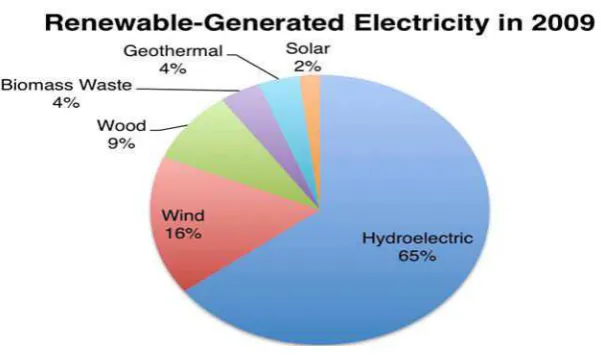
Figure 2.1: The percentage of renewable generated electricity in 2009 ... 3
Figure 2.2: The impoundment type ... 5
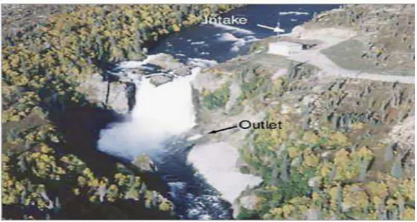
Figure 2.3: A diversion type... 5
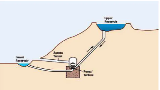
Figure 2.4: The pumped storage type ... 6
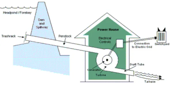
Figure 2.5: The small hydro process ... 7
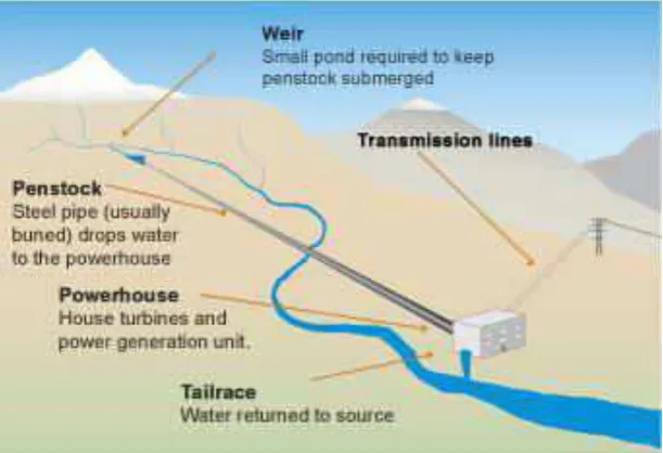
Figure 2.6: The run of river type ... 8
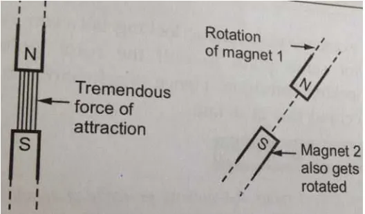
Figure 2.7: The locking method ... 9
Figure 2.8: The construction of synchronous motor ... 10
Figure 2.9: The construction of PMSM ... 11
Figure 2.10: The software of ANSYS Maxwell... 14
Figure 2.11: General Design Parameter ... 15
Figure 3.1: The flow chart of this project ... 18
Figure 3.2: The design and simulation by using ANSYSY Maxwell ... 19
Figure 3.3: The flow chart of the software development ... 21
Figure 3.4: The flow chart the design of generator ... 22
Figure 3.5: The starting the Ansys Maxwell ... 23
Figure 3.6: Select the machine type ... 23
Figure 3.7: List in the project manager ... 24
Figure 3.8: The properties of stator data ... 24
Figure 3.9: View of the stator ... 25
Figure 3.10: Properties of winding arrangement... 26
Figure 3.11: The winding of the stator ... 27
Figure 3.12: Properties window of rotor data ... 28
Figure 3.13: Properties window of rotor pole data ... 28
Figure 3.14: View of the rotor... 29
Figure 3.15: List in the optimetrics setup... 30
Figure 3.16: List in the project manager ... 30
Figure 3.17: Properties windows of solution data ... 31
Figure 3.18: The performance view ... 32
Figure 3.19: The design sheet ... 33
Figure 3.20: The performance view ... 33
Figure 3.21: Create Maxwell design box displayed ... 34
Figure 3.22: The base design in project manager ... 35
Figure 3.23: Material assigned ... 36
Figure 3.24: Design generator in 2DMaxwell... 36
Figure 4.1: The generator ... 38
Figure 4.2: Output power versus speed curve ... 39
Figure 4.3: Output torque versus speed curve ... 40
xiv
Figure 4.5: The generator in 2DMaxwell ... 41
Figure 4.6: Torque curve ... 43
Figure 4.7: Winding Current curve ... 43
Figure 4.8: Induced Voltage versus speed curve ... 44
Figure 4.9: Mesh Plot ... 45
xv
xvi
LIST OF SYMBOLS AND ABBREVIATIONS
FEM = Finite Element Method
PMSM = Permanent Magnet Synchronous Motor
1 hot water. The hot water will be collected in a pool and steam produced by the hot water going through the turbine and generator will generate electricity. Hydroelectric is electricity generated by hydropower, the production through use of the gravitational force of falling or flowing water. Water flowing into the turbine and drive the generator and convert the motion of blade rotates to electrical energy.
2
1.2 Problem Statement
The problem statements are:
i. Now day’s hydroelectric power is not a new technology, this study is use the same principle of run-of-river but on a smaller scale.
ii. This study supplies the water from the river to generate the power energy.
1.3 Objectives
The objectives are:
i. To design an In-Pipe-generator using Anysy Maxwell.
ii. To conduct a performance simulation by the aid of FEM software.
1.4 Work Scope
The work scopes are:
i. This project will focus on simulation.
3
CHAPTER 2
LITERATURE REVIEW
2.1 Introduction
In the developing world and the growing demand for clean living environment, renewable energy has generated high interest. Hydropower is the source of renewable energy. According to the pie chart show in figure 2.1, hydropower is the most popular type to generate electricity. 65% hydroelectric, 16% for wind, 9% wood, and biomass waste 4%. While for geothermal is 4% and solar 2%. Electric energy generation is a process where the energy source is converted to electrical energy. This project use run-of-river type generator concept generally known as mini-hydro technology. Basically, run of river use the generator outside from the pipe to generate the electric, but in this project is use the generator inside the pipe to generate the electric energy.
4
2.2 The potential Hydropower in Malaysia
Malaysia has a large population and a insufficient of energy. There are states with 3.8% of electricity coverage. Furthermore, Malaysia has states with rural areas such as Sabah and Sarawak. To reduce the problem of weak electricity in rural areas, renewable energy sources is the best solution. Malaysia potential use of renewable energy sources such as small hydro because this country has a lot of places that are suitable for generating electricity and it can also have benefited the population (Borhanazad et al. 2013). In Malaysia, there are 189 names of rivers and streams along the 57,300km, these rivers have potential to be used to produce hydropower for Malaysia. However, the use of hydropower can cause people to lost ground for agriculture because it requires a large area to be used as water reservoirs (Department of Energy Management and Industry Development, 2010). The impact of small
There are type of hydropower which is impoundment, diversion and pumped storage. Impoundment is most common type of hydroelectric power plant. An impoundment normally a large hydropower uses a dam to store river water in a reservoir. Figure 2.2 shows the part of impoundment.
5
Figure 2.2: The impoundment type
Next, figure 2 shows a diversion is one type of hydropower sometimes call run of river, facility channels a portion of a river trough a canal or penstock. It doesn’t need use any storage. The water supplied from the water stream that contain generator (Tunde 2005).
Figure 2.3: A diversion type
6
upper reservoir when electricity demand is low. For the period of high electricity demand, water will released back into the tank and turn a turbine and generate the electricity.
Figure 2.4: The pumped storage type
2.3.2 Classification According To Capacity
Hydropower has been classification according to capacity. For large hydro capacity is less than 100MW, medium hydro capacity is around 15MW to 100MW. While, for small hydro the capacity from 1MW to 25MW and mini hydro have capacity greater than 100KW but less than 1MW). The micro hydro have capacity from 5KW to 100KW and the capacity of Pico hydro is less than 5KW (Sharma & Singh, 2013).
2.4 Small Hydro
7
,1979). Small hydro can produce electric for home, farm or ranch. It will stop generating when the river to dry because it produces electricity generated by the flow of river water (Tunde, 2005). There are many advantages of small hydro because it is the technology used to generate electricity in areas that difficult to get electricity and don’t has fuel cost and low cost of maintenance (Khan, 2014). The advantages of small hydro are no pollution either the air or the environment and also save the costs for maintenance. Other than that, we do not need to spend a lot of capital because it does not require fuel to generate electricity. Furthermore small hydro is a technology that can survive for long periods of time.
Figure 2.5: The small hydro process
2.5 Run of River plant
8
this increase the capacity of the stream in time for several months (Sharma & Singh, 2013). Run of the river is when the turbine and generator are located either in dam or found alongside it (Tunde, 2005). Water Canal is permanent component. The generator will not generate the energy if there is no water stream. Water pipeline needed to bring the water to the machine whether it’s short or move away. A few characteristics that should be considered for a pipe is the pipe length depend on the distance from the supply to generator. In addition to the pressure inside of the pipe should also be taken to determine how much power used and most the type of pipe use the form of polyethylene or PVC (Gatte et al. 2010).The function of turbine is when water flows through it at a rate of speed. The turbine will rotate in the water speed. The power generated depends on the velocity of the water. There are different types of turbine such as Kaplan, pelton and others. The Figure 2.6 is shows an overview of the run-of-river.
9
Synchronous motor is a rotating machine. Synchronous motor can function as a generator and as a motor. Generator supplies current to the load resistance connected to the output of the engine is driven at a speed which is given by a prime mover which may be a turbine or engine. Motor, it is a mechanical load driving at a certain speed when input terminal is supplied by a dc voltage. The generator converts mechanical energy into electrical energy. motor while also converting electrical energy into mechanical energy (K.dutta 2012). They are synchronous, AC, permanent magnet motors, which are very flexible and efficient. They do require complicated control electronics. The rotor contains great permanent magnets. There are no coils of wire in the rotor and no electrical connections to it. This increases reliability over DC motors which have windings in the rotors. All windings are in the stator. The control electronics passes an alternating current through these windings to turn the rotor. This current must be "synchronous" with the rotor's movement. This synchronous motor operated only at synchronous speed. The principle operated for synchronous motor as locking method. When the magnet that has south and north face each other they have attracted between two poles. If magnet 1 is rotated the magnet 2 also rotates in same direction with same speed because there has attraction as shown in figure 5. For this condition called magnetic locking.