UNIVERSITI TEKNIKAL MALAYSIA MELAKA
Effects of Tool Length in Milling Operation
Thesis submitted in accordance with the partial requirement of the
Malaysia Technical University of Malacca for the degree of
Bachelor of Manufacturing Engineering (Manufacturing Process)
By
AHMAD FHADLI BIN SALLEH
Faculty of Manufacturing Engineering
UTeM Library (Pind.1/2005)
UNIVERSITI TEKNIKAL MALAYSIA MELAKA (UTeM)
BORANG PENGESAHAN STATUS TESIS*
JUDUL: EFFECTS OF TOOL LENGTH IN MILLING OPERATION
SESI PENGAJIAN: 2007/ 2008
Saya AHMAD FHADLI BIN SALLEH
mengaku membenarkan t esis (PSM/ Sarj ana/ Dokt or Falsaf ah) ini disimpan di Perpust akaan Universit i Teknikal Malaysia Melaka (UTeM) dengan syarat -syarat kegunaan sepert i berikut :
1. Tesis adalah hak milik Universit i Teknikal Malaysia Melaka.
2. Perpust akaan Universit i Teknikal Malaysia Melaka dibenarkan membuat salinan unt uk t uj uan pengaj ian sahaj a.
3. Perpust akaan dibenarkan membuat salinan t esis ini sebagai bahan pert ukaran ant ara inst it usi pengaj ian t inggi.
4. **Sila t andakan (√)
SULIT
TERHAD
TIDAK TERHAD
(Mengandungi maklumat yang berdarj ah keselamat an at au kepent ingan Mal aysia yang t ermakt ub di dalam AKTA RAHSIA RASMI 1972)
(Mengandungi maklumat TERHAD yang t elah dit ent ukan oleh organisasi/ badan di mana penyelidikan dij alankan)
(TANDATANGAN PENULIS)
* Tesis dimaksudkan sebagai t esis bagi Ij azah Dokt or Falsaf ah dan Sarj ana secara penyelidikan, at au disert asi bagi pengaj ian secara kerj a kursus dan penyelidikan, at au Laporan Proj ek Sarj ana Muda (PSM). ** Jika t esis ini SULIT at au TERHAD, sila lampirkan surat daripada pihak berkuasa/ organisasi berkenaan
Tel : 06-233 2421, Faks : 06 233 2414 Email : [email protected]
UNIVERSITI TEKNIKAL MALAYSIA MELAKA
Karung Berkunci 1200, Ayer Keroh, 75450 Melaka
FAKULTI KEJURUTERAAN PEMBUATAN
Rujukan Kami (Our Ref) : 20 May 2008
Rujukan Tuan (Your Ref):
Pust akawan
Perpust akawan Universit i Teknikal Malaysia Melaka UTeM, Ayer Keroh
MELAKA.
Saudara,
PENGKELASAN TESIS SEBAGAI SULIT/ TERHAD
- TESIS SARJANA MUDA KEJURUTERAAN PEMBUATAN (PROSES PEMBUATAN): AHMAD FHADLI BIN SALLEH
TAJUK: EFFECTS OF TOOL LENGTH IN MILLING OPERATION
Sukacit a dimaklumkan bahawa t esis yang t ersebut di at as bert aj uk “ Effect s of Tool Lengt h in Milling Operat ion” mohon dikelaskan sebagai t erhad unt uk t empoh lima (5) t ahun dari t arikh surat ini memandangkan ia mempunyai nilai dan pot ensi unt uk dikomersialkan di masa hadapan.
Sekian dimaklumkan. Terima kasih.
“ BERKHIDMAT UNTUK NEGARA KERANA ALLAH”
DECLARATION
I hereby, declare this thesis entitled “Effects of Tool Length in Milling Operation” is the results of my own research except as cited in the reference.
Signature : ………. Author’s Name : ………
Date : ………
APPROVAL
This PSM submitted to the senate of UTeM and has been as partial fulfillment of the requirements for the degree of Bachelor of Manufacturing Engineering (Manufacturing Process). The members of the supervisory committee are as follow:
………. Main Supervisor
ABSTRACT
ABSTRAK
DEDICATION
ACKNOWLEDGEMENTS
First and foremost, I would like to express my highest appreciation to my supportive academic supervisor, Mr. Raja Izamshah B. Raja Abdullah for his supervision and support in completing this thesis.
Mr Jaafar, the technician leader, for his eager assistance and for providing equipment that was required. Also, I want to thank Mr Afendy and Mr Fauzi for their help in conducting and teaching the CNC milling to fulfill this thesis.
TABLE OF CONTENTS
List of Abbreviations, Symbols, Specialized Nomenclature xi
1.0INTRODUCTION 1 1.1 Problem Statement 2
1.2 Objectives 3 1.3 Scope 3
2.0 LITERATURE REVIEW 4 2.1 Computer Numerical Control (CNC) milling machine 4 2.1.1 CNC Milling Operation 5
2.1.2 Selection for Milling Cutter 6
2.2 The Effect of the Surface and Tool in CNC Milling Operation 8 2.2.1 The Influence Factor of the Cutting Condition 8
2.2.2.1 Correlation of Deflection Experimental Value with Simple Model 12 2.2.2.2 Stiffness of the Shank and Tool Holder 13 2.2.2.3 Cutting Force Error Determination 14
2.2.3 Influence of Tool Run-Out 15 2.5.2 Impact of Milling Stability onto Machined Surface Roughness 20
2.5.3 Surface on Unstable Milling 21 2.5.4 The Factor Effect of the Surface Roughness 22 2.6 Overview Design Experiment (DOE) 24
2.6.1 The Role and Implication of DOE 24 2.6.2 Orthogonal Array (OA) 25
3.0 METHODOLOGY 27
3.1 Introduction 27
3.6.1.1 Surface Roughness Measurement 41 4.2.1 Analysis for Significant Parameter 47 4.2.2 Surface Roughness Analysis for Mild Steel Material 47 4.2.3 Surface Roughness Analysis for Tool Steel Material 51
4.3 Chip Thickness Result 56
LIST OF FIGURES
2.1 Effect milling cutting diameter workpiece travel 7 2.2 Tool path direction in three-axis ball-end milling of an inclined surface 8
2.2a Up- ramping 8
2.2b Down ramping 8
2.2c Down-cutting contouring 8
2.2d Up-cutting countering 8
2.3 Type of milling cutter 11 2.4 Deflection test on the machine and result for ball-end mill Ø 8mm. 11 2.5 Deflection verification test of the cantilever beam model, and points
where the deflection is measured 12 2.6 Diagram representing the tests performed on the machine 13 2.7 Slot C and Hole B cutting test along X axis in forward direction. 14 2.8 Representative scanning electron microscopy (SEM) figures of tool wear 17 2.9 Chip Form Produced in Machining Operation 19 2.10 Profile of the machined surface and workpiece simulation deflected
during unstable milling 22
2.11 Pair means comparison for spindle levels 23 2.12 Pair means comparison for depth levels 23
3.10 Portable Surface Roughness Tester 41 3.11 Surface roughness measurement 42
3.12 Metallurgy Microscope 42
3.13 Dial Calliper 43
3.14 Measure the chip thickness 44
LIST OF TABLES
2.1 Classical Array 26
2.2 Taguchi Arrays 26
3.1 Gantt Chat for PSM 1 29 3.2 Gantt Chat for PSM 2 30 3.3 The Level of Process Parameter for Mild Steel 31 3.4 The Level of Process Parameter for Tool Steel 32 3.5 Orthogonal Array table for experiment use Mild Steel workpiece 32 3.6 Orthogonal Array table for experiment use Tool Steel workpiece 33 3.7 Machine Specification of CNC Milling Machine 36 3.8 The machining G-Code programme 37
4.1 The result for Mild Steel material 46 4.2 The result for Tool Steel material 46 4.3 Mean value of surface roughness for Mild Steel 1020
for each 2- way interaction 51 4.4 Mean value of surface roughness for Tool Steel
LIST OF ABBREVIATIONS, SYMBOLS, SPECIALIZED
NOMENCLATURE
% - percent µ - micro
µm - micro meter cm - centimeter
CAM - computer aided manufacturing CNC - computer numerical control DOE - design of experiment DoF - degree of freedom in - inch
LF - distance to the force application point m - meter
mm - millimeter OA - orthogonal Array PC - personal computer Ra - arithmetic mean value
Rq - root mean square average
Rt - peak to peak surface rughness
CHAPTER 1
INTRODUCTION
1.0 Introduction
The CNC Milling is one of the advanced machining that can automatically operate without too many operator handled. However the most important thing in CNC machining operation is the code of programming and the tool set up. The tool set up is a crucial step as it will influence the quality of machined part.
There are many factors that influence the results of machining operation such as the coolant, type of tools, materials, speed and feed rate. These problems may happen when the machining operation does not refer to the suitable schedule of operation and choose the wrong parameters. Before any machining operations are run, all related parameters must take into account. This is because it can avoid any waste in any product produced and increase the capability of machine and tool life. Besides, it can reduce any redundant of cost to any companies by producing a quantity of quality products.
The vibration of the cutting tool will be generated during the machining if the tool is tied at short length. This situation may happen due to the force of the mill increase while the tool stands in poor condition. The tool may be broken when the force is increased or during high speed.
The result of this experiment can be obtained by taking measurements of surface roughness on the workpiece, chip produced and also rate of tool wear. The Portable Surface Roughness Tester will be utilised to take the measurement of the surface roughness and the thickness of the chips will be recorded. All the measurements taken will be determined by using appropriate graphs to monitor the effects of tool length with the variable parameters involved in this experiment.
1.1 Problem Statement
Usually, the tool length will be set up by inserting the tool into the tool holder until it will fit and lock. So, the tool length of this experiment will be divided into two values which are 12/18 and 14/18 of the overall tool length. These values may influence the effect of the surface roughness, chips produced and as well as tool wear. The vibration and the force during the machining are also the dominant factors that influence the results.
1.2 Objectives
The purposes of this project are:
i. To find the suitable tool length value of cutter during milling operation. ii. To find the effects of surface roughness for different tool length in milling.
iii. To find the significant machining parameters that influences the surface roughness in milling.
1.3 Scope
The scopes of this project are:
i. To machine Mild Steel and Tool Steel using different tool length and machine parameters.
ii. To obtain the surface roughness by milling operation. iii. To observe the tool wear using metallurgy microscope.
CHAPTER 2
LITERATURE REVIEW
2.1 Computer Numerical Control (CNC) Milling Machine
Computer numerical control (CNC) is the machines that can operate automatic refer
to the program that was setting and the code inserted to the PC and it will transfer to
the machine. Other, CNC milling machines or machining centers is computer
controlled vertical mills with the ability to move the spindle vertically along the
Z-axis.Usually; the CNC Milling can perform the functions of drilling and often
turning. CNC machines today are controlled directly from files created by CAM
software packages, so that a part or assembly can go directly from design to
manufacturing without the need of producing a drafted paper drawing of the
manufactured component.
CNC milling uses a computer program written in a notation called G-code, which
conforms to the EIA-274-D standard. CNC milling machines feature a rotating
cylindrical cutter with multiple flutes, known as an endmill. The endmill is capable
of traveling along multiple axes and is used for machining techniques such as slots,
pockets, and profiles (Ananymous, 2005a).
Other types of machining centers are primarily milling and boring machines which
can perform a variety of other operation such as drilling, reaming, and tapping
without changing the part set up. They are sometime referred to as multitasking
CNC milling is a technology whereby a machine tool is driven by a computer to
produce a desired shape. The Computer Numerical Control computer is programmed
to drive the motors attached to each of the machines moving axes in a discrete
manner to create the cutting action, which will produce the desired shape in a work
piece
2.1.1 CNC Milling Operation
A milling machine is a machine tool used for the complex shaping of metal and other
solid materials. Its basic form is that of a rotating cutter or endmill which rotates
about the spindle axis as similar to a drill and a movable table to which the
workpiece is affixed. That is to say, the cutting tool generally remains stationary
while the workpiece moves to accomplish the cutting action. Milling machines may
be operated manually or under computer numerical control. Some machines might
even make 1000 parts on a weekend with no operator, checking each part with lasers
and sensors.
The function of CNC Milling machine can refer to the G-Code that transfer to the
control panel. This code will make the machine run refer to the program that had
download to the control panel. The several types of instruction will do of this
machine were:
a) Movement: The most basic motion for a controller is to move the machine
tool along a linear path from one point to another. Some machine tools can
only do this in XY, and have to accept changes in Z separately. Some have
two further axes of rotation to control the orientation of the cutter, and can
move them simultaneously with the XYZ motion.
b) Tool Changes: Originally there would be a G-code instruction telling the
of different tools which they can change themselves pneumatically,
hydraulically, and electromechanically.
c) Drilling: A tool can be used to drill holes by pecking to let the sward out.
Using a special tapping tool and the ability to control the exact rotational
position of the tool with the depth of cut, it can be used to cut screw threads.
d) Drilling Cycle: A drilling cycle is used to repeat drilling or tapping operations
on a workpiece. The drilling cycle accepts a list of parameters about the
operation, such as depth and feed rate. To begin drilling any number of holes
to the specifications configured in the cycle, the only input required is a set of
coordinates for hole location. The cycle takes care of depth, feed rate,
retraction, and other parameters that appear in more complex cycles. After the
holes are completed, the machine is given another command to cancel the
cycle, and resumes operation.
e) Parametric Programming: A more recent advancement in CNC interpreters is
support of logical commands, known as parametric programming. Parametric
programs incorporate both G-code and these logical constructs to create a
programming language and syntax similar to basic comment.
2.1.2 Selection for Milling Cutter
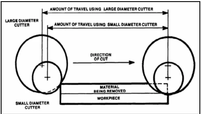
There were very important to choose the suitable during the machining process. It
will avoid any defect the machine and the product produce. Figure 2.1, show the
effect of cutting diameter during the machining process. Consider the following
when choosing milling cutters:
a) 45° angular cuts may either be made with a 45° single angle milling cutter
while the workpiece is held in a swivel vise, or with an end milling cutter
b) Use a coarse-tooth milling cutter for roughing cuts and a finer-toothed
milling cutter for light cuts and finishing operations.
c) When milling stock to length, the choice of using a pair of side milling
cutters to straddle the workpiece, a single side milling cutter, or an end
milling cutter will depend upon the number of pieces to be cut.
d) High-speed steel, stellite, and cemented carbide cutters reamer shank. In
this case, one or two side milling have a distinct advantage of being capable
of rapid cutters, a fly cutter, or an end milling cutter may be used roduction
when used on a machine that can reach the proper speed.
e) The milling cutter should be small enough in diameter so that the pressure
of the cut will not cause the workpiece to be sprung or displaced while
being milled.
Figure 2.1: Effect milling cutting diameter workpiece travel (Stephenson and
2.2 The Effect of the Surface and Tool in CNC Milling Operation
The tool length also effects the machining operation of the surface roughness of the
workpiece. This machining process also influence by the speed rate, dept of cut and
feed rate. This situation will show the effect by the chip produce and result of the
surface roughness.
According to the Raksiri, (2004) on his studies the other major cause of inaccuracy in
CNC milling machine is error due to cutting force. The error in workpiece is caused
either by excessive deformation at the tool and workpiece interface due to cutting
action or by deformation of machine tool structure.
2.2.1 The Influence Factor of the Cutting Condition
There were many direction of milling cutting during produce the product or any
machining part. The cutting condition can be the factor of the surface roughness
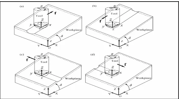
result in milling operation. Refer to the Dudzinski, (2007) on his studies about the
cutting force in ball-end milling with tool-surface and predictive force. Figure 2.2
shows direction cutting influence force in milling operation.
Figure 2.2: Tool path direction in three-axis ball-end milling of an inclined surface.
(a) Up- ramping, (b) down ramping, (c) down-cutting contouring, and (d) up-cutting