UNIVERSITI TEKNIKAL MALAYSIA MELAKA
DEVELOPMENT OF VISE FOR DRILLING MACHINE
This report submitted in accordance with requirement of the Universiti
Teknikal Malaysia Melaka (UTeM) for the Bachelor Degree of Manufacturing
Engineering (Manufacturing Management) with Honours.
By
MOHD ZULHILMI BIN OMAR
Faculty of Manufacturing Engineering
oval
!
"
#$
$
%$
$
&$
$
'$
((
)*
+,-.
* ./ +,-.
./ . ,.- *. ,.
* #01%
+,-.
.2 . .23.2 +2 )*
.
"
24 #%56)2 '7 #75
2 /4 +,. * 4)*
. . %5
89#775 / .). )
,
" #7 . ,*) %770
"
.2 . .23.2 +2:+)*.
;
,
"
" <<<<<<<<<<<<<<<<
( * = > 5
> 5 ) $
(( 6 )* +,-. 5
DECLARATION
I hereby, declared this report entitled “Development of Vise for Drilling Machine” is the results of my own research expect as cited in references
Signature : __________________________________________ Author’s Name :
APPROVAL
The report is submitted to the Faculty of Manufacturing Engineering of UTeM as a partial fulfillment of the requirements for the degree of Bachelor of Manufacturing Engineering (Management) with Honours. The member of the supervisory committee
is as follow:
(Signature of Supervisor)
APPROVAL
The report is submitted to the Faculty of Manufacturing Engineering of UTeM as a partial fulfillment of the requirements for the degree of Bachelor of Manufacturing Engineering (Management) with Honours. The member of the supervisory committee
is as follow:
(Signature of Principal Supervisor)
………
(Official Stamp of Principal Supervisor)
(Signature of Co-Supervisor)
ABSTRACT
ABSTRAK
DEDICATION
Thankful to Allah S.W.T for the opportunity to finish this project
Specially dedicated to
Omar Ismail,Sahara Wahid En. Shafiq Jumali, brother and sisters
ACKNOWLEDGEMENT
First of all, I would like to thank the Almighty Allah for His blessings and His power for me to complete this Projek Sarjana Muda.
I would like to take this opportunity to express my deepest gratitude to my project supervisor, En. Shafiq bin Jumali who has persistently and determinedly assisted me during the whole course of this project. It would have been very difficult to complete this project without the enthusiastic support, insight and advice given by him.
My outmost thanks also go to my family who has given me support throughout my academic years. I would like to thank them for understanding and always giving me courage and the strength I need to carry on this project. Without them, I might not be the person I am today.
TABLE OF CONTENT
Abstract i
Abstrak ii
Ancknowledgement iii
Table of Content v
List of Table viii
List of Figures ix
List Abbreviations xi
1. INTRODUCTION 1
1.1 Background 1
1.2 Problems Statement 2
1.3 Objectives and Aims of this Project 2
1.4 Scope and Limitation of Project 2
1.5 Importance of Project 2
1.6 Outline of Report 3
2. LITERATURE REVIEW 4
2.1 Definition of Drilling Machine 4
2.2 Parts of Machine 6
2.3 Standard Operations of Drilling Machine 8
2.4 Principal Types of Drilling Machine 8
2.5 Types of Drilling Machines 9
2.6 Introduction of Vise 14
2.7 Vise System 20
2.8 Types of Vise System 21
2.8.1 Hydraulic System 21
2.8.2 Pneumatic System 22
2.9 Previous Case Study 23
2.9.1 Vise for a Directional Drilling Machine 23
2.9.3 Adjustable Clamp Jaws 24 2.9.4 Vise for Holding a Workpiece on an EDM Machine 24
2.9.5 Replaceable Vise Jaw Insert Assembly 25
2.9.6 Portable Vise 25
2.9.7 Hold-Down Device for Movable Jaw of a Vise 26 2.9.8 Precision Machine Tool Vise with Self Adjusting Clamp 26
2.9.9 Vise with Two Sets of Clamping Jaws 27
2.9.10 Flexible Jaw Vise Accessory for Irregular Objects 27
3. METHODOLOGY 29
3.1 Planning of the Study 29
3.1.1 Process Flow Diagram 29
3.1.2 Gantt Chart 31
3.2 Data Collection 31
3.2.1 Primary Data Collection 31
3.2.1.1 Field Observation 34
3.2.1.2 Archival Collections 34
3.2.2 Secondary Data 34
3.2.2.1 Book, Internet and Journal 35
3.3 Phase of Project 35
3.3.1 Phase 1: Selection of System 36
3.3.2 Phase 2: Design a vise 36
3.3.3 Phase 3: Produce Physical Part 37
3.3.3 Phase 4: Pneumatic System Installation 39
3.3.4 Phase 5: Testing Performance of Vise 39
4. VISE DESIGN 40
4.1 Material 40
4.2 Workpiece 41
4.3 Product Structure Tree 41
4.4 Mechanical Design 43
4.4.1 Jaw Part 43
4.4.2 Cover Part 44
4.4.4 Pin Part 45
4.5 Pneumatic Design 48
4.5.1 Fitting 48
4.5.2 Pressure Gauge 49
4.5.4 Push button 50
4.5.6 Directional Valve 51
5. RESULT AND DISCUSSION 53
5.1 Pneumatic Test 53
5.2 Clamping Test 57
5.2.1 Result of Clamping Test 59
5.3 Drilling Test 60
5.3.1 Result of Drilling Test 61
5.4 Surface Roughness Test 62
5.4.1 Result of Surface Roughness Test 63
5.5 Result and Discussion of the Project 67
6. CONCLUSION AND RECOMMENDATION 68
6.1 Conclusion 68
6.2 Future Recommendations 69
REFERENCES 70
APPENDICES A Gantt Chart
LIST OF TABLES
2.1 Types of Drilling Machine 10
2.2 Types of Vise 17
3.1 The Differences between Primary and Secondary Data 33
3.2 Types of Machine Used 39
4.1 Mechanical Part Used in the Vise 46
4.2 Dimension of the Vise 46
4.3 Pneumatic Component Used in the Vise 52
5.1 Result of Clamping Test 59
5.2 Result of Drilling Machine 61
5.3 Result at Part 1 before Drilling Process 63 5.4 Result at Part 1 after Drilling Process 63
5.5 Result Part 2 before Drilling Process 64
5.6 Result Part 2 after Drilling Process 64
5.7 Result Part 3 before Drilling Process 65
LIST OF FIGURES
2.1 Drilling Machine. 5
2.2 Parts of Machine. 6
2.3 Parts of Radial Drill Machine 7
3.1 Process Flow. 32
3.2 Drawing of New Vise 37
4.1 Workpiece Used in this Project 41
4.2 Product Structure Tree 42
4.3 Jaw Part 43
4.4 Cover Part 44
4.5 Base Part 44
4.6 Pin Part 45
4.7 Physical Part of the Vise 47
4.8 Fitting Component 48
4.9 Pressure Gauge Component 49
4.10 Pressure Gauge Symbol 49
4.11 Flow Controller Component 50
4.12 Flow Controller Symbol 50
4.13 Push Button Component 50
4.14 Push Button Symbol 50
4.15 Directional Valve Component 51
4.16 Directional Valve Symbol 51
4.17 Complete Component 51
5.1 Pneumatic Diagram 54
5.2 Pneumatic Diagram before Running Program 54 5.3 Pneumatic Diagram When Push Button 1 has Push 53 5.4 Pneumatic Diagram When Push Button 2 has Push 53
5.6 Clamping Test 55
5.7 Top View while Clamping Test 57
5.8 Left Side View while Clamping Test 58
5.9 Right Side View while Clamping Test 59
5.10 Top View while Drilling Test 60
5.11 Side View while Drilling Test 60
5.12 Surface Roughness Diagram 62
5.13 Area of Part 1 63
5.14 Area of Part 2 64
5.15 Area of Part 3 65
5.16 Surface Roughness Test 66
5.17 Finished Vise 67
LIST OF ABBREVIATIONS
ANSI - America National Standard Institute ABS - Acrylonitrile/ Butadiene/ Styrene CNC - Computer Numerical Control FKP - Fakulti Kejuruteraan Pembuatan ISO - International Standards Organization NC - Normally Closed
PFD - Process Flow Diagram
CHAPTER 1
INTRODUCTION
This chapter is intended to provide background information of the study. It covers background of study, problem statements, objectives, scope and limitation of project, important of project, and outline of project
1.1 Background
Traditional drill vises provide a clamping jaw which has only one angle of attack in order to effect clamping. The clamping jaw is limited so it may only be moved laterally in the direction of the main body. However, the disadvantages of the structure is the workpiece being clamped is of an irregular shape and where one desires to bend the workpiece along the edge of the device while it is clamped
In addition, traditional drill vises also do not provide for an adequate working surface which can be utilized for working on the workpiece during the clamping thereof. Finally, traditional vises of which aware are not readily adaptable for use anywhere on the surface of a machine, but rather, are adapted to be used only at an edge thereof.
1.2
Problems Statement
Nowadays, in global market have many design of drill vise. Every manufacture compete each others in order to produce good product. However there is no one of vice can clamp for crooker shape with direct clamp till today. So, by producing this project, the problem can be solving in the future.
1.3 Objectives and Aims of this Project
In the preparation of this project, a few objectives have been identified. The main objectives of this study are to identify:
1. To propose solution problem related vise tool for holding irregular shape 2. To produce prototype vise that can holding irregular shape for drilling
machine
3. Develop application of vise system in drill vise
1.4 Scope and Limitation of Project
The scope of this project is only focus on development of vise in drill vise. Design for the vise only produce prototype. This project is only focused on hold a irregular workpiece by two jaws. This project not covers types of material and specific process for market product because of the researcher ability time and financial constrain limit. The project is started from July 2008 until December 2008. Result of this project for drill vise only. The project is only covered
1.5
Importance of Project
The importance of project is to:
3. Improve accuracy during drill a workpiece
4. Improve performance of produce in manufacturing industry 5. Reduce vibration during drilling process
1.6 Outline of Report
The Gant-chart has been constructed in managing this project (see appendix A).This project encompasses five (5) chapters which are:
Chapter 1
This chapter provide the introduction of this project, describes the background and problem statement of the project. The objective, scope, importance of the project and the project outline are also presented in this chapter.
Chapter 2
This chapter provides the literature review about drilling machine, parts of drilling machine and types of drilling machine. The literature review covered about vise, types of vise, vise system and previous case study.
Chapter 3
In this chapter will give the readers an overview of research methodology, presents the appropriate methodology of this project. This chapter includes the project process planning, flowchart, Gantt chart, and data analysis.
Chapter 4
In addition this discusses the analysis and discussion, present findings of the project.
Chapter 5
CHAPTER 2
LITERATURE REVIEW
2.1
Definition of Drilling Machine
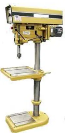
From the resource of Krar, F.S (2005), the drilling machine or drill press is essential in any metalworking shop. Basically, a drilling machine consists of a spindle which turns the drill and can be advanced into the work, either automatically or by hand and a work table (which holds the workpiece rigidly in position as the hole is drilled). A drilling machine is used primarily to produce holes in metal. However, operations such as tapping, reaming, counterboring, countersinking, boring, and sport facing can also be performed. Figure 2.1 at below show the drilling machine.
Drill Press machine also define a machine used for drilling operations available in a wide variety of types and size to suit different types and sizes of workpieces (Rapisarda, M. 1996). Drilling machines are used for drilling holes, tapping, reaming, and small-diameter boring operations. The workpiece is placed on an adjustable table, either by clamping it directly into the slots and holes on the table or by using a vise, which in turn is clamped to the table. The drill is lowered manually by a hand wheel or by power feed at preset rates. Manual feeding requires some skill in judging the appropriate feed rate.
According to Kibbe, R.R (2002), drilling holes is one of the most basic of machining operations that is very frequently done by machinist. Metal cutting requires considerable pressure of feed on the cutting edge. A drill press provides the necessary feed pressure either by hand or power drive. The primary use of the drill press is to drill holes, but it can be used for other operations such as countersinking, counterboring, spot facing, reaming, and tapping, which are processes that modify the drilled hole.
[image:21.612.288.392.309.522.2]Lastly, based on Oswald (1999), drill machine is machine to grip, revolve, and feed a twist drill in order to produce a hole in a piece of metal or other material
2.2
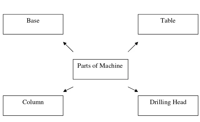
Parts of Machine
Figure 2.2: Parts of Machine
From the resource of Krar, F.S. (2005), although drill presses are manufactured in a wide variety of types and sizes, all drilling machines contain certain basic parts. The main parts on the drilling machine are base, column table, and drilling head. In base part, a material made by cast iron for provides stability for the machine and rigid mounting for the column. The base usually has holes so that it may be bolted to a table or bench. The slots in the base allow the workholding device or the workpiece to be fastened to the base. Figure 2.2 at the top show the parts of the machine.
According to study of Rapisarda, M. (1996), another main part in drilling machine is column. Column is an accurate cylindrical post that fits into the base. The table, which is fitted on the column, may be adjusted to any point between the base and head. The head of the drill press is mounted near the top of the column.
Table is one of part for drilling machine. The table, either round or rectangular, is used to support the workpiece to be machined. The table whose surface is at 90 degree in either direction for drilling holes on a angle. Slots are provided in most tables to allow jigs, fixtures, or large workpiece to be clamped directly to the table (Krar , S. 2002)
Parts of Machine
Table Base
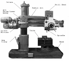
[image:22.612.170.509.86.294.2]Last part of drilling machining is drilling head. Drilling head mounted close to the top of the column, contains the mechanism which is used to revolve the cutting tool and advance it into the workpiece. The head contains the spindle, a round shaft that holds and drives the cutting tool, and is housed in the spindle sleeve or quill. The spindle sleeve does not revolve but can move up and down inside the head to provide a down feed for the cutting tool. The end of the spindle may have a tapered hole to hold taper-shank tolls, or it may be threaded or tapered for attaching drill chuck. The hand feed lever is used to control the vertical movement of the spindle, sleeve and the cutting tool. A depth stop, attached to the spindle sleeve, can be set to control the dept that cutting tools enter the workpiece (Krar, F.S. 2005). Figure 2.23 at the below show the parts of the radial drill machine.
[image:23.612.183.465.294.545.2]
2.3
Standard Operations of Drilling Machine
Drilling machines may be used for performing a variety of operations besides drilling a round hole. A few of the more standard operations, cutting tool, and work setups will be briefly discussed.
1) Drilling maybe defined as the operation of producing a hole by removing metal from a solid mass using a cutting tool called a twist drill
2) Countersinking is the operation of producing a tapered or cone shaped enlargement to end of a hole
3) Reaming is the operation of sizing and producing a smooth, round hole from a previously drilled or bored hole with the use of a cutting tool having several cutting edges.
4) Boring is the operation of truing and enlarging a hole by means of a single-point cutting tool, which is usually held in a boring bar.
5) Spot-facing is the operation of soothing and squaring the surface around a hole to provide a seat for the head of a cap screw or a nut.
6) Tapping is the operation of cutting internal threads in a hole with a cutting tool called a tap.
7) Counterboring is the operation of enlarging th top of a previously drilled hole to a given depth to provide a square shoulder for the head of a bolt or cap screw.
2.4