Microanalysis of the developed porous
titanium alloy
Abstract
Research in biomedical materials has received increasing attention recently. In particular, porous titanium alloys are attractive due to their unique physical, mechanical, and biocompatibility properties. The aim of this work is to analys the microstructure of the developed porous titanium alloy produced by powder metallurgy based on the expansion of pressurized argon bubbles technique. This fabrication procedure involved blending of elemental powder, i.e., Ti, Nb, Ta, Zr, pressurized gas infusions, densification using HIP (Hot Isostatic Press) and pores expansion at 1350oC for 10 hours in vacuum followed by furnace cooling. Foamed specimens were characterized for microstructure and microhardness by optical microscopy and scanning electron microscopy, and Vickers indentation, respectively. Porosity levels of the porous titanium alloy in the range of 14.8-40,2% have been achieved with pore sizes in the range of 18.2-190 m. The porosity level increased with the increase of argon backfill pressure. Microstructures of the porous titanium alloys exhibited the presence of -phase and platelets within the -phase matrix. Homogenization of the alloy was completed indicating that the phases grew along with pore expansion. The hardness of the prominent phase was found being comparable to the range being used in parts produced by conventional techniques.
Keywords: titanium a lloy, porous structure, powder metallurgy
Introduction
Titanium and its alloys are extensively utilized for biomedical applications, such as bone repair or reconstruction, due to their excellent biocompatibility, high specific strength and high corrosion resistance [1-3]. However, it is well known that the elemental composition of titanium alloy implant materials must be carefully selected from the viewpoint of biocompatibility in order to eliminate any harmful side-effects to the neighbouring tissue. For example, the release of ions from metals such as Al, V, Ni, Fe and Cr, some of which are commonly used to alloy Ti, is known to adversely affect the human body [4-5]. In contrast to this, the use of β-stabilizing elements such as Nb, Ta and Zr has been reported to result in Ti alloys with good biocompatibility [6] with the added advantage that these elements would also be expected to produce alloys with enhanced strength and, when being compared to pure Ti and α-Ti, a decrease in elastic modulus will be more compatible with that of bone [7].
The use of porous structures could minimize foreign body reaction to the implant leading to
the generation of a strong bone-implant interface bond. From the literature study, although
there is still controversy over definite agreement on the pore size for bone ingrowth [8-17],
ingrowth to enhance osseointegration. The use of inert gas, such as argon, to promote
porosity due to the expansion of pressurized argon bubbles within a metal matrix at elevated
temperature has been first introduced by Kearns et al. [18]. The amount and morphology of
the porosity can be controlled by the foaming parameters such as backfill pressure, foaming
temperature or foaming time. This technique has led to development of porous pure titanium
[19] and titanium alloys based on prealloyed starting powder [18, 20, 21]. Alternatively, the
use of elemental powder as starting materials is a much simpler, more flexible, and
potentially more cost effective route. Critical concerns have been raised from the use of
elemental powders regarding whether alloying can be accomplished under the conditions
required to fabricate highly porous titanium alloys. Therefore, this work presents results
about the porous Ti-Nb-Ta-Zr development by powder metallurgy based on the expansion of
pressurized argon bubbles technique. The main contribution is on the microstructural
development following the foaming procedure.
Materials and Methods
specimens. Using this machine, a specimen with a thickness up to 5 mm was placed onto the plastic sample holder by mild adhesive. Pore morphology and microstructure of the alloy were observed by scanning electron microscopy (SEM) type Zeiss Evo 40XVP with a voltage of 15-20 kV and working distance of 8-11 mm and also by optical microscope type Eclipse ME 600 from Nikon, Japan. EDS analysis with INCA peak matching software used was carried out to determine chemical compositions of these phases in the alloy. Image analysis using ImageJ version 1.43u (National Institute of Health USA) software was employed to obtain pore size and pore distribution. Microhardness measurements were carried out with load of 100 gf and holding time of 5 s
Result and Discussion
(a) (b)
Figure 1. Backscattered scanning electron micrograph of the mixed powder (a) and corresponding energy spectra from EDS measurement (b)
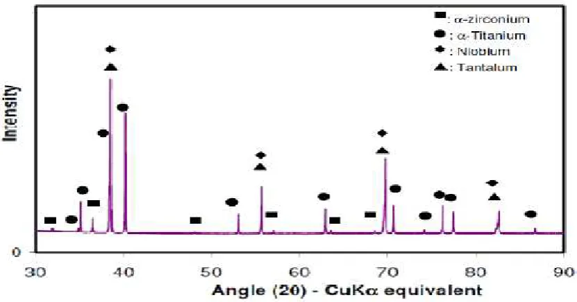
Laboratory x-ray diffraction (XRD) was also used to examine the crystallographic geometry of
the elemental powders and to detect the possible presence of other phases after the blending
procedure. The x-ray diffraction pattern of the as-mixed powders are shown in Figure 2, which
indicate the presence of peaks related to individual elements; the structure of both hexagonal
close packaged (hcp), i.e. α-titanium, α zirconium, and isomorphous body centered cubic (bcc)
structure, i.e., niobium and tantalum. Any additional phases produced after the blending
procedure was not detected.
Figure 2. Diffraction patterns of samples of the mixed powder
Ta Nb
Ti
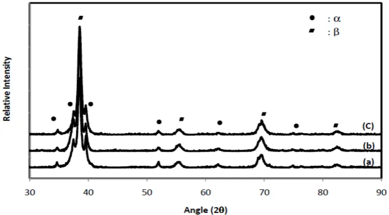
Following the foaming procedure, the XRD patterns of the foamed specimens showed peaks
corresponding to the presence of β−phase and α−phase as shown in Figure 3. Patterns similar to the XRD spectra of the specimens with different argon backfill pressures (Figure 3(a),(b) and (c))
were found. Whilst the development of the phases continued to take place by foaming procedure, the effect of an increase in argon backfilled pressure was found being insignificant with regard to the spectra. Of interest, the β−phase peaks were found to become more pronounced
compared to the α−phase peaks indicating the proportion of β−phase predominantly exists
compared to α−phase does.
Figure 3. X-ray diffraction patterns of the foamed Ti-Nb-Ta-Zr powder at 1350oC with argon backfill pressure of (a) 0.34 MPa, (b) 0.86 MPa , (c) 0.48 MPa
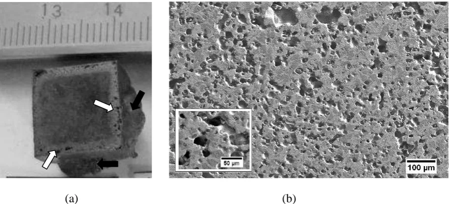
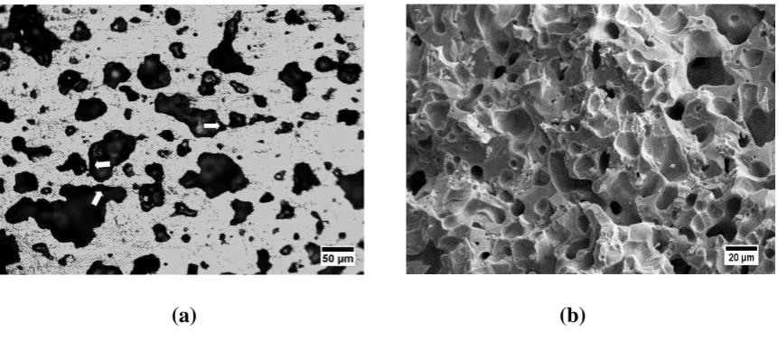
Prior to the pore size and pore morphology evaluation, foamed specimens being visually observed as shown in Figure 4(a) shows a foamed specimen which was EDM cut and light polished on the top, depicting two distinct region i.e. a larger pore size area – close to the specimen’s surface (black spot pointed by white arrow) and a smaller pore size area – the deeper area which is found to be relatively uniform in pore size. In addition, metal bubbling (black arrow) was found on the surfaces of some specimens. Regarding this, the evaluations (porosity, pore size and mechanical properties evaluation) were subjected to the area with smaller pores – the deeper area. The dimensional changes of the specimen following foaming procedure were clearly observed. After being cut, removal of surface damage layer and being polished, the foamed specimens were examined for phase identification and pore size and their morphology. The area being examined in the section referred to the area closed to the specimen centre except specifically stated. Figure 4(b) shows a typical microstructure of a specimen foamed at 1350oC/0,86 MPa/10 hours achieving a porosity level of 38,5 vol%.
(a) (b)
Figure 4. Image of specimen isothermally foamed titanium alloy at 1350oC (a), secondary electron micrograph showing pore morphology of a specimen foamed at 1350oC/0,86 MPa/10 hours
(38,5%)(b).
pore expansion in addition to the phase appeared as islands surrounded by phase. Those structures were found being dispersed across the specimen. This result is in a good agreement with the XRD examination.
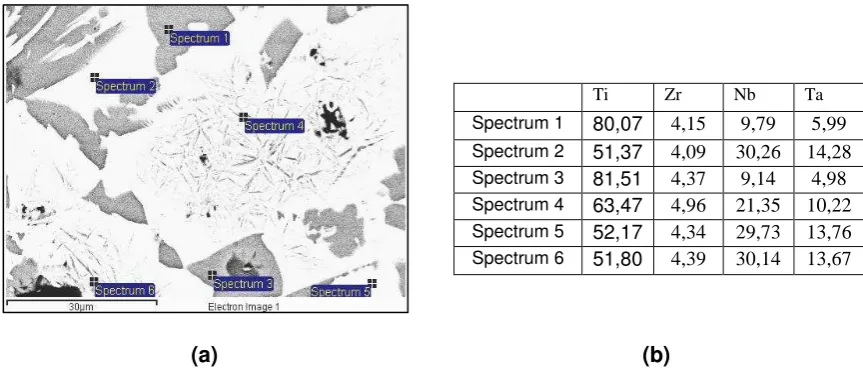
A higher magnification of the foamed specimen’s microstructure examined by BSE-SEM and their chemical composition were shown in Figure 5.
Ti Zr Nb Ta
Spectrum 1 80,07 4,15 9,79 5,99
Spectrum 2 51,37 4,09 30,26 14,28
Spectrum 3 81,51 4,37 9,14 4,98
Spectrum 4 63,47 4,96 21,35 10,22
Spectrum 5 52,17 4,34 29,73 13,76
Spectrum 6 51,80 4,39 30,14 13,67
(a) (b)
Figure 5 Micrograph of foamed specimen showing 3 distinct areas (a), chemical composition of the areas (b).
The figure confirm that the darker regions consist of the elements in which being dominated by
titanium representing phase. Conversely, the chemical composition of light grey area is close to that of the expected alloy composition Figure 5(b). This indicates a higher niobium content in -phase, since niobium promotes a strong stabilization of this phase. However, although niobium, in compositional terms, can be considered a neutral elements, it strongly acts in the -phase stabilization, significantly decreasing the -transus temperature. In this regards formation of -phase structure may be retarded [22].
highest pore area fraction being measured were typically found being 7.5-189 m and of 59.6-94.5 m, respectively, as depicted in Figure 6(b).
(a) (b)
Figure 6. Porosity level of the porous titanium alloy achieved versus argon backfill pressure (a), typical pore size distribution of a specimen foamed at 1350oC/0,86 MPa/10 hours with porosity level of 38,5 vol% (b)
The elongated pores due to pores joined and the equiaxed rounded pores morphologies were observed. The pathway from one pore to the next had grown to a larger size. The pore walls generally remained thick with more often the connectivity being observable. Faceted pores which is reported being observed in Ti-6Al-4V alloy[18] or CP Ti [25] foamed was not found in this study. Yet an absence of the faceted pores was also reported by previous research [21]. An early stage of pore coalescence during isothermal foaming at 1350oC leaving round protrusion of less than 44 m in diameter as illustrated in Figure 7(a).
0
Argon Backfill Pressure (MPa) Pore Diameter (m)
(a) (b)
Figure 7. Optical micrograph showing early stage of pore coalescence during isothermal foaming at 1350oC/0,86MPa/10 hours (a), fracture surface of foamed specimen showing faceted mode of failure and acomplished sintered alloy (b)
Rupturing of some side pore walls due to pore expansion (foaming) was also observed, indicating that many pores had coalesced with multiple pores sometimes having become interconnected. The foaming rate is known to decrease and further expansion will reduce when pore volume increase. An incresase in pore volume decreases pore pressure which is known as the driving force. In addition, the pore expanding through the specimens surface will also decrease the foaming rate due to escaping the pressurized argon.
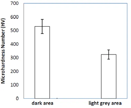
Figure 8. Hardness values of the phases observed in the sample
The microhardness values of the phases as depicted in Figure 8 were examined by microhardness tester (HV). The hardness values of the light grey area area was found being lower (323,6±33 HV) than that of the dark area (529,8 ±52,4 HV). Increasing Nb and Ta content as a -phase stabilizer may decrease the hardness values [22]. The hardness value of -phase is comparable to the hardness value commonly reported for hot wrought alloys about 350 HV [27]. Yet this values is higher than that of titanium alloy fabricated by conventional P/M method sintered at 1600oC (300 HV) [24]. Hardness values of the dark area is in a good agreement to that of cast designed titanium alloy [28].
Conclussions
homogenization of the alloy was completed. The hardness values of the prominent phase (326 HV) observed in the samples are within the range used in parts produced by conventional techniques.
Acknowledgment
The authors wish to thank the Australian Nuclear Science and Technology Organisation (ANSTO) in Sydney, NewSouth Wales, for carrying out the HIPing and foaming procedures.
Reffrences
1 Bai, Z. and Gilbert, e.L. Corrosion performance of stainless steels, cobalt, and titanium alloys in biomedical applications. In Cramer, S.D. and B.S. Covino, J., eds. ASM
Handbook, Corrosion: Environments and Industries, pp. 837-853 (ASM International, 2006).
2 Gotoh, E. and Okazaki, Y. Corrosion resistance, mechanical properties, fatigue properties, and tissue response of Ti-15Zr-4Nb-4Ta alloy. Journal of ASTM International, 2006, 2(9), 15.
3 Long, M. and Rack, H.J. Titanium alloy in total joint replacement-a materials science perspectives. Biomaterials, 1998, 19, 1621-1639.
4 Hildebrand, H.F., Veron, C. and Martin, P. Nickel, chromium, cobalt dental alloys and allergic reactions: an overview. Biomaterials, 1989, 10(8), 545-548.
5 Silva, H.M., Schneider, S.G. and Neto, C.M. Study non toxic aluminium and vanadium-free titanium alloys for biomedical applications. Materials science and Engineering C, 2004, 24(5), 679-682.
6 Eisenbarth, E., Velten, D., Muller, M., Thull, R. and Breme, J. Biocompatible of -stabilizing elements of titanium alloys. Biomaterial, 2004, 25, 5705-5713.
7 Song, Y., Xu, D., Yang, R., Li, D., Wu, W.T. and Guo, Z.X. Theoritical study of the effects of alloying elements on the strength and modulus of -type bio titanium alloys. Materials science and Engineering A, 1999, 260, 269-274.
8 Hulbert, S., Young, F., Mathews, R., Klawiter, J., Takbert, C. and Stelling, F. Potential of ceramic materials as permanently implantable skeletal prostheses. Journal of Biomedical Materials Research, 1970, 4, 433-456.
9 Spector, M., Flemming, W.R., Kreutner, A. and Sauer, B.W. Bone growth into porous high-density polyethylene. Journal of Biomedical Materials Research, 1976, 10(4), 595-603.
10 Nilles, J.L., M., C.J. and Wilson, C. Biomechanical evaluation of bone-porous material interfaces. Journal of Biomedical Materials Research, 1973, 7, 231.
11 Welsh, R.P., Pilliar, R.M. and Macnab, I. Surgical implants-the role of surface porosity in fixation to bone and acrylic. Journal of bone & Joint surgery, 1971, 53A. 12 Cameron, H.U., Pilliar, R.M. and Macnab, I. The rate of bone ingrowth into porous
13 Itala, A.I., Ylanen, H.O., Ekholm, C., Karlsson, K.H. and Aro, H.T. Pore diameter of more than 100 micrometer is not requisite for bone ingrowth in rabbits. Journal of Biomedical Materials Research, 2001, 58, 679-683.
14 Bobyn, J.D., Cameron, H. and Weatherly, G. The optimum pore size for the fixation of porous surfaced metal implant by ingrowth of bone. Clin Orthop, 1980, 150, 263-270. 15 Ayers, R.A., Simske, S.J., Bateman, T.A., Petkus, A., Sachdeva, R.L.C. and
Gyunter, V.E. Effect of nitinol implant porosity on cranial bone ingrowth and
apposition after 6 weeks. Journal of Biomedical Materials Research, 1999, 45(1), 42-47. 16 Bobyn, J.D. and Miller, J.E. Features of biologically fixed devices. In Simon, S., ed.
Orthopaedic Basic Science. Chicago: American Academy of Orthopaedic Surgeons1994).
17 Frosch, K.H., Barvencik, F., Dresing, K., Lohmann, C.H., Viereck, V., Siggelkow, H., Breme, J. and Stuermer, K.M. Migration, matrix production & lamellar bone formation of human osteoblast-like cell in porous Ti implants. Cells Tissues Organs, 2002, 170, 214-227.
18 Kearns, M.W., Blenkinsop, P.A., Barber, A.C. and Farthing, T.W. Manufacture of a novel porous materials. Metals and Materials (Institute of Metals),, 1987, 3(2), 85-88. 19 Davies, N.G., Teisen, J., Schuh, C. and Dunand, D.C. Solid state foaming of Ti by
superplastic expansion of argon-filled pores. J. Mater. Res, 2001, 16(5), 1508-1519. 20 Ashworth, M.A., Jacobs, M.H., Unwin, P. and Blunn, G. The development and
characterisation of porous Ti-6Al-4V manufactured by hot isostatic pressing for orthopaedic apllications. Proceedings of 7th World Biomaterials Congress-2004, pp. 1394, May, 17-24 2004, Sydney, Australia, 2004).
21 Oppenheimer, S. Proccessing and characterization of porous Ti-6Al-4V and NiTi Materials Science and Engineering, p. 170 (Northwestern University, Illinois, 2007). 22 Tang, X., Ahmed, T. and Rack, H.J. Phase Transformation in Ti-Nb-Ta and
Ti-Nb-Ta-Zr Alloys. Journal of Materials and Science, 2000, 35, 1805-1811.
23 Sakaguchi, N., Niinomi, M., Akahori, T., Takeda, J. and Toda, H. Relationships between tensile deformation behavior and microstructure in Ti-Nb-Ta-Zr system alloys. Materials Science and Engineering: C, 2005, 25(3), 363-369.
24 Taddei, E.B., Henriques, V.A.R., Silva, C.R.M. and Cairo, C.A.A. Production of new titanium alloy for orthopaedic implants. Materials science and Engineering C, 2004, 24(5), 683-687.
25 Murray, N.G.D. and Dunand, D.C. Effect of thermal history on the superplastic expansion of argon-filled pores in titanium: Part I kinetics and microstructure. Acta materialia, 2004, 52(8), 2269-2278.
26 Nugroho, A.W., Leadbeater, G. and Davies, I.J. Processing and properties of porous Ti-Nb-Ta-Zr alloy for biomedical applications using the powder metallurgy route. Australian Journal of Mechanical Engineering, 2011, 8(2), 169.
27 Allvac. An Allegheny Technology Company, Catalogue).
28 Niinomi, M., Akahori, T., Takeuchi, T., Katsura, S., Fukui, H. and Toda, H.