EFFECT OF CUTTING PARAMETER ON SURFACE
ROUGHNESS TITANIUM ALLOY (Ti-6Al-4V) WITH
DRILLING PROCESS
SITI SARA BINTI MUSTAFA
B051110034
UNIVERSITI TEKNIKAL MALAYSIA MELAKA
EFFECT OF CUTTING PARAMETER ON SURFACE ROUGHNESS TITANIUM
ALLOY (Ti-6Al-4V) WITH DRILLING PROCESS
This report submitted in accordance with requirement of the Universiti Teknikal Malaysia Melaka (UTeM) for the Bachelor Degree of Manufacturing Engineering
(Manufacturing Process) (Hons.) by
SITI SARA BINTI MUSTAFA
B051110034
920812146606
UNIVERSITI TEKNIKAL MALAYSIA MELAKA
BORANG PENGESAHAN STATUS LAPORAN PROJEK SARJANA MUDA
TAJUK: Feasibility Study of Drilling Process on Titanium Alloy SESI PENGAJIAN: 2014 / 2015 Semester 1
Saya SITI SARA BINTI MUSTAFA
mengaku membenarkan Laporan PSM ini disimpan di Perpustakaan Universiti Teknikal Malaysia Melaka (UTeM) dengan syarat-syarat kegunaan seperti berikut:
1. Laporan PSM adalah hak milik Universiti Teknikal Malaysia Melaka dan penulis. 2. Perpustakaan Universiti Teknikal Malaysia Melaka dibenarkan membuat salinan untuk
tujuan pengajian sahaja dengan izin penulis.
3. Perpustakaan dibenarkan membuat salinan laporan PSM ini sebagai bahan pertukaran antara institusi pengajian tinggi.
4. **Sila tandakan ( ) SULIT
TERHAD
(Mengandungi maklumat yang berdarjah keselamatan atau kepentingan Malaysia sebagaimana yang termaktub dalam AKTA RAHSIA RASMI 1972)
(Mengandungi maklumat TERHAD yang telah ditentukan oleh organisasi/badan di mana penyelidikan dijalankan)
** Jika Laporan PSM ini SULIT atau TERHAD, sila lampirkan surat daripada pihak berkuasa/organisasi berkenaan dengan menyatakan sekali sebab dan tempoh laporan PSM ini perlu dikelaskan sebagai SULIT atau TERHAD.
DECLARATION
I hereby, declared this report entitled Effect of cutting parameter on surface roughness Titanium Alloy (Ti-6Al-4V) with drilling process is the results of my own research except as cited in references.
Signature : ……….
Author’s Name : SITI SARA BINTI MUSTAFA
APPROVAL
This report is submitted to the Faculty of Manufacturing Engineering of UTeM as a partial fulfillment of the requirements for the degree of Bachelor of Manufacturing Engineering (Manufacturing Process) (Hons.). The member of the supervisory is as follow:
i
ABSTRAK
ii
ABSTRACT
iii
DEDICATION
iv
ACKNOWLEDGEMENT
Praise to Allah for giving me chances as to complete this project and I would like to thank my supervisor Dr Mohd Amri bin Sulaiman for his advice and guidance in completing this project.
I wish to express my gratitude to assistant engineer En Azuan, Pn Aisyah, and En Taufik for helping me throughout this project. Not forgotten, my group members for their support and contribution of idea while doing this project.
v
1.1 Background of the project 1
1.2Problem Statement 3
2.1.1 Cutting condition in drilling process 8 2.1.2 Previous research on drilling process 10
2.2 Titanium Alloys 10
2.2.1 Application of titanium alloys 11 2.3 Cutting Tool Material for Titanium Alloys 12
2.3.1 Cemented Carbides 12
2.4 Surface Integrity 13
vi
2.5.1 Measuring Surface Roughness 15
2.5.2 Surface Finish in Drilling 16 2.5.3 Ranges of Surface Finish in Conventional Machining Operation 17 2.5.4 Effect of Machining Parameter on Surface Roughness 17
2.6 Design of Experiment (DOE) 19
2.7 Factorial Design 20 2.8 Previous Research on Surface Roughness when drilling Ti-6Al-4V 22
CHAPTER 3 : METHODOLOGY 3.2 Machine, Drill bits and Workpiece Material 27
3.2.1 Machines 27
3.2.2 Workpiece Material 28 3.2.3 Drill bits 29
3.3 Selection of Parameter 30 3.4 Planning Matrix Design Full Factorial 31 3.5 Experimental Procedures 32 3.6 Collecting and Analyzing the Data 33
3.7 Full Factorial Data Analysis 34
vii 4.4.3 3D response surface graph 55 4.5 Chip production during drilling process 56
CHAPTER 5 : CONCLUSION
5.1 Conclusion 58
5.2 Recommendation 59
REFERENCES 60
viii
LIST OF FIGURES
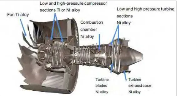
Figure 1.1 Cross section of jet engine 2
Figure 1.2 Fatigue crack on aeroplane 4
Figure 2.1 Drilling phases 8
Figure 2.2 (a) Surface roughness and (b) roughness profile 14
Figure 2.3 Schematic diagram for stylus 16
Figure 2.4 Ranges of Surface Finish for Machining Operations 17
Figure 2.5 Graph of Feed Rate and Cutting Speed against Surface Roughness 18
Figure 2.6 Surface roughness against cutting speed, feed rate and point angle 19
Figure 2.7 Design matrix 21
Figure 2.8 Regression model 21
Figure 2.9 Surface Roughness Graph 23
Figure 2.10 Surface Roughness obtained when using coated 23
and uncoated drill bits
Figure 2.11 Graph of Surface Roughness against the cutting time 24
Figure 3.1 Flow chart of the project 27
Figure 3.2 (a)CNC Mazak Variaxis 630-5x (b)G-Code 29
Figure 3.3 Titanium Alloy (Ti-6Al-4V) 30
ix Figure 3.5 Mitutoyo SJ-301 portable surface roughness tester 34
Figure 3.6 Summary analysis of full factorial 35 Figure 4.1 Bar graph of surface roughness value at 38
different cutting speed and feed rate
Figure 4.2 Surface profile 40
Figure 4.2 Half normal plot of the factor effect 42
Figure 4.3 Bar graph showing error between experimental and model 46
Figure 4.4 Tool wear at the end of experiment 47
Figure 4.5 Box Cox Plot 47
Figure 4.6 Normal Plot of Residual 48
Figure 4.7 Residuals vs. Predicted 48
Figure 4.8 Combination graph 50
Figure 4.9 One factor plot for cutting speed vs surface roughness 52
Figure 4.10 Formation of BUE 53
Figure 4.11 One factor plot for feed rate vs surface roughness 55
Figure 4.12 3-D response surface for feed rate and cutting speed 56
Figure 4.13 (a) Chip formation at the cutting speed 40 m/min and feed rate 0.02 mm/rev
x
LIST OF TABLE
Table 2.1 Recommended parameter for drilling process 8
Table 3.1 Mazak variaxis 630-5x specification 29
Table 3.2 Composition of Ti-6Al-4V 30
Table 3.3 Mechanical Properties of Ti-6Al-4V 31
Table 3.4 KCT drill bit specification 32
Table 3.5 Parameter specification 32
Table 3.6 Parameter specification for cutting speed 33
Table 3.7 Parameter specification for feed rate 33
Table 3.8 Process control parameter and their limit 34
Table 3.9 Design matrix by using design software 34
Table 4.1 Surface roughness value at different cutting speed and feed rate 41
Table 4.2 ANOVA analysis for surface roughness 43
Table 4.3 Percentage error between experimental and predicted 45
Table 4.4 Confirmation result after validation test 49
Table 4.5 Criteria require for optimum surface roughness parameter 49
Table 4.6 Optimization parameter for surface roughness 50
Table 4.7 Confirmation test result 51
1
CHAPTER
1
INTRODUCTION
This chapter discusses background of the project, problem statement, objectives, scope and outline of the project.
1.1 Background of the project
2 Figure 1.1 : Cross section of jet engine (Ulutan et al., 2011)
Many manufacturing methods such as power metallurgy, isothermal forging and casting has been introduced to reduce the cost for manufactured of titanium components. However, conventional machining are still remains as a popular choice when manufactured titanium parts. Drilling is one of the crucial machining process for aerospace industries especially in airframe production. In addition, drilling mainly involved in the final steps of mechanical components fabrication and it economic impact is significant.
Moreover, it is estimated that 60% of all part the rejection are due to the poor hole quality as the holes are drilled in the finished product, hence poor quality of holes produced results in manufacturing loss. This will eventually increases the manufacturing costs and decresed the production rate (Hocheng 2005). Surface roughness, burr and hole diameter and cylindricity are classified as hole quality. By referring to Zareena et al. (2001), higher surface roughness results in lower capability to resist corrosion, serious wear and catastrophic fatigue hence reducing the performance of titanium alloy.
3 surface properties and condition of material performance. According to Palanikumar et al. (2006), surface roughness is crucial in determining evaluation of machining accuracy. The are many factors that could contribute to the quality of surface roughness such as cutting tool geometry, cutting parameter, microstructure of the work piece, Built-up Egde (BUE) formation, tool and workpiece vibration and etc. Hence, the ideal surface finish is hard to achieve due to reason stated above (Groover 2007).
Hence, in order to improve hole quality during drilling process of the titanium alloy, it is essential to determine factors, methods, and drill bit during drilling operation. Hole quality depends on the machining conditions such as cutting speed, feed rate, presence of coolant, depth of cut, cutting tool material and etc.
1.2 Problem Statement
In aerospace industry, titanium alloy (Ti-6Al-4V) are favourable and widely used due to its superior properties. In fact, around 40%-60% drilling process are used for material removal processes and this technique is crucial in aerospace industries to produce a hole.
4 titanium. Higher surface roughness results in lower capability to resist corrosion, serious wear and catastrophic fatigue hence reducing the performance of titanium alloy. (Zareena et al., 2001). Hence this study is important in order to determine the suitable drilling parameter in order to obtain good surface quality.
.Figure 1.2: Fatigue crack on aeroplane (Surface Integrity of Machine Surface, 2010)
1.3 Objectives
The objectives of this study is :
i) To determine the effect of drilling parameter (cutting speed, feed rate) to the surface roughness of hole produced
ii) To develop a mathematical model using ANOVA analysis for surface roughness iii) To obtain an optimized drilling parameter for Ti-6Al-4V
1.4 Scope of the project
5
1.5 Organization
Chapter 1 is the introduction the project which includes background of the project, problem statement, objectives to be achieved and scope.
Chapter 2 is the literature review of this study and projects which consists the introduction the titanium alloy, effects of drill bits on drilling titanium alloy, and influence of process parameter on surface roughness. It reviews about the relevant information to the study.
Chapter 3 is the methodology of this project which contain the approach, methodology and procedure used in this project. All the procedures will be explain and it is consisting of many aspects such as type of machines to be used, selection of drill bits, selection of material to be machined, parameters involved, equipment and method to analyze the surface roughness.
Chapter 4 represent the result and discussion after results is attain from the experiment. This chapter discussed the finding of the obtained result. The analysis of the data is made statistically by using analysis of variance (ANOVA) from Design Expert Software
6 This chapter presents related study done by previous research on the surface roughness of titanium alloy in drilling machining. The purpose of this chapter is to gather the information that could contribute to this project. This literature review will focus on the drilling process, cutting tool material, surface integrity, surface roughness, effect of machining parameter on surface roughness. In addition, this chapter also discuss about titanium alloy and its application.
2.1 Drilling Process
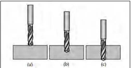
According to Tonshoff et al. (1998), drilling process is one the most important metal cutting operation and approximately 30% of the metal cutting operation comprised of drilling process. Drilling is a process which uses multi-point tool for material removal process in order produce a hole and can be carried out by using either conventional or CNC machine. According to Sharif et al. (2012), there are three steps involved in drilling operations. Firstly is centering phase, secondly is the full drilling phase and lastly the break through phase. The first phase is most important in order to prevent the deterioration of the drill from happened and premature wear and torque and thrust force on the tool are constantly increasing in this phase. In addition, once the cutting edges are engaged the full drilling phase occurred and drill point breaks through the underside of the workpiece indicating that the break through phase has begin. The process of drilling is stopped once the drill body passed through the workpiece.
7 Figure 2.1 : Drilling phases, (a) centering phase (b) full drilling phase (c) break through
phase ( Machinability of Titanium Alloy, 2006)
Table 2.1 : Recommended parameter for drilling process (Kalpakjian & Schmid 2010)
2.1.1 Cutting conditions in drilling
Rotational speed of drilling is determined by using the following formula. Let N represent the spindle rev/min
N =
8 Feed, f in drilling is specified in mm/rev (in/rev). Recommended feeds are propotional to drill diameter, higher feeds are used with larger diameter drills. Feed can be converted to feed rate into the equation :
There are two types of drilled holes produce in drilling, which are through holes or blind hloes. Through holes can be calculated by using this formula :
where = machining (drilling) time, min; t = work thickness, mm (in); = feed rate, mm/min (in/min); and A= an approach allowance that accounts for the drill point angle, representing the distance the drill must feed into the work before reaching full diameter. This allowance is given by
A = 0.5 D tan
where A = approach allowance, mm(in); and 0 = drill angle.
In blind hole, the depth d is defined as the distance from the work surface to the depth of the full diameter. The equation is given below
where A = the approach allowance
The rate of material removal in drilling is determined as the product of the drill cross-sectional area and the feed rate