UNIVERSITI TEKNIKAL MALAYSIA MELAKA
DESIGN CHILDREN ALERT SYSTEM USING RADIO
FREQUENCY FM TECHNIQUES
This report submitted in accordance with requirement of the Universiti Teknikal Malaysia Melaka (UTeM) for the Bachelor‟s Degree in Electronic Engineering
Technology (Telecommunication) (Hons.)
by
NUR FATIN HUSNA BINTI SHARUDIN B071110176
910616085528
UNIVERSITI TEKNIKAL MALAYSIA MELAKA
BORANG PENGESAHAN STATUS LAPORAN PROJEK SARJANA MUDA
TAJUK: Design Children Alert System Using Radio Frequency FM Techniques
SESI PENGAJIAN: 2014/15 Semester 2
Saya NUR FATIN HUSNA BINTI SHARUDIN
mengaku membenarkan Laporan PSM ini disimpan di Perpustakaan Universiti Teknikal Malaysia Melaka (UTeM) dengan syarat-syarat kegunaan seperti berikut:
1. Laporan PSM adalah hak milik Universiti Teknikal Malaysia Melaka dan penulis. 2. Perpustakaan Universiti Teknikal Malaysia Melaka dibenarkan membuat salinan
untuk tujuan pengajian sahaja dengan izin penulis.
3. Perpustakaan dibenarkan membuat salinan laporan PSM ini sebagai bahan pertukaran antara institusi pengajian tinggi.
4. **Sila tandakan ( )
SULIT
TERHAD
TIDAK TERHAD
(Mengandungi maklumat yang berdarjah keselamatan atau kepentingan Malaysia sebagaimana yang termaktub dalam AKTA RAHSIA RASMI 1972)
(Mengandungi maklumat TERHAD yang telah ditentukan oleh organisasi/badan di mana penyelidikan dijalankan)
DECLARATION
I hereby, declared this report entitled “Design Children Alert System Using Radio Frequency FM Techniques” is the results of my own research except as cited in
references.
Signature : ……….
Author‟s Name : ………
APPROVAL
This report is submitted to the Faculty of Engineering Technology of UTeM as a partial fulfillment of the requirements for the degree of Bachelor of Engineering Electronic Technology (Telecommunication) (Hons.). The member of the supervisory is as follow:
i
ABSTRAK
ii
ABSTRACT
iii
DEDICATION
iv
ACKNOWLEDGEMENT
v
List Abbreviations, Symbols and Nomenclatures xi
vi
2.9.4 Frequency Modulation signal 23
2.10 Components 24
2.10.1 Trimmer capacitor 25
2.10.2 Electret Condenser Microphones 25
vii
CHAPTER 4: RESULT & DISCUSSION 46
4.1 Introduction 46
4.2 Expected Result 46
4.3 Preliminary Result 47
4.4 RF Transmitter 48
4.5 RF Receiver 56
CHAPTER 5: CONCLUSION & FUTURE WORK 57
5.1 Conclusion 57
5.2 Limitation 58
5.3 Future work 59
REFERENCES 60
APPENDICES
A List of frequency FM that used in Ayer Keroh,Melaka B NE SE 555 Timer Datasheet
C Schematic of FM Transmitter
D PCB Layout FM Transmitter E PCB Top silk FM Transmitter
viii
Statistic children missing 2014 (JAN-FEB)
2
The parameters of a frequency modulated signal Material for potentiometer
List frequency of FM that used at Ayer Keroh,Melaka Observation of tone signal square wave when potentiometer resistance difference
Square wave signal which output from FM Transmitter Voltage at battery and time taken for range 5m
Voltage at battery and time taken for range 17m
50 51
ix
LIST OF FIGURES
2.1 Block diagram of Transmitter 7
2.2 Block diagram of Receiver 8
2.3 Electromagnetic Spectrum 10
2.4 Wavelength 11
Relationship between modulation index and bandwidth Frequency Modulation signal
Variable capacitor
Electret Condenser Microphone
Two terminal of Electret Condenser Microphone Three terminal of Electret Condenser Microphone Potentiometer
555 Timer Block Diagram
Internal arrangement of 555 Timer
15
3.1 Basic FM Transmitter Circuit 35
3.2 Tuning the frequency 36
3.3 Tone Generator circuit 36
3.4
Tone Generator circuit with potentiometer Tone Generator circuit without potentiometer Proteus Software
Schematic RF Transmitter built in Proteus software Analyse circuit
Using UV insulator machine
x
Frequency between FM Transmitter and receiver FM Transmitter
Waveform of tone generator circuit using VCC=5V Waveform of tone generator circuit using VCC=9 Graph of voltage versus time for range 5m
xi
LIST OF ABBREVIATIONS, SYMBOLS AND
NOMENCLATURE
DSTFT - Discrete short-time Fourier Transform
EM - Electromagnetic
gt /gr - Power gain of transmitting (or receiving) antenna
GHz - Gigahertz
Hz - Hertz
IF - Intermediate frequency
xii
- Received power
- Radiated power
RF - Radio Frequency
TV - Television
- Wavelength
1
1.1 Background
Radio frequency or usually known as RF is defined as the rate of oscillation that being measured in Hertz (Hz) between frequency ranges of 30 kHz to 300GHz. Radio Frequency is used to transmit signal and also receive a signal.
Nowadays, children missing happen frequently as their parent not alert and lost sight with their children. These situations usually occur when they are doing outdoor activities or in a public area. This project will presents the alert system on which it capable to avoid the children from lost by limit the safety distance between parent and child. For this project Radio Frequency FM techniques were used in which a small portable device as a medium between parent and children. This consists of a Radio Frequency transmitter and receiver. Both transmitter and receiver are small portable devices which to easier parent and their children bring it everywhere and anywhere.
The analogy that we can create for this project is the transmitter is present with the children while the receiver part is carried out by the parents. RF transmitter with the child will continuously transmit the RF signal to the RF receiver that carried by the parents. If the child walk and leave the parents until reach the distance limit, the RF signal will stop transmit to the receiver. During the RF signal is transmitting, it will emit a sound which functioning to alert parent that their children still in the
INTRODUCTION
2 range of distance limitation until the sound is stop means that their children is out of range. These children alert system is particularly designed to avoid missing children and alert their parent from lose sight of their children.
1.2 Problem statement
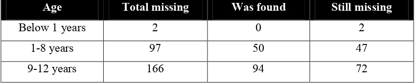
As we know it is not easy to handle children especially when we are at public area which full with people and everywhere have interesting things which attract children to go near or get that thing. It is also difficult to parents or guardian consistence and always keeps an eye on their children all the times and eventually still will lose sight of children. This will tend to miss their children either their children still in the area of that place or maybe was being kidnapped. Other than that, parents also usually late realize their children are missing from them. These will take a long time to find back and maybe their children have been far away at the times they realize it. Table 1.1, 1.2 and 1.3 below shows the statistic of missing children from 2012 to 2014 (February).
Table 1.1: Statistic children missing in 2012
Age Total missing Was found Still missing
Below 1 years 2 0 2
1-8 years 97 50 47
9-12 years 166 94 72
Table 1.2: Statistic children missing in 2013
Age Total missing Was found Still missing
Below 1 years 8 2 6
1-8 years 93 39 54
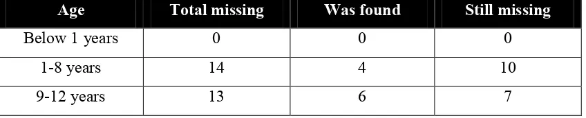
3 Table 1.3: Statistic children missing in 2014 (JAN-FEB)
Age Total missing Was found Still missing
Below 1 years 0 0 0
1-8 years 14 4 10
9-12 years 13 6 7
1.3 Project Objectives
To develop children alert system that is in pair of portable devices.
To ensure parents alert with their children from missing occur in limitation distance.
To introduce an alert system that makes parents feels safer toward their child safety when they are at public area.
1.4 Work scope
4 software before jump to fabricate. The result of simulation can be obtained and analyzed before move to last step which perform the system hardware.
1.5 Report overview
5
2.1 Introduction
In this chapter, the method and theory will be described and discussed which related to this project. A few sources such as an articles, journal, newspaper and documentations were used to get knowledge regarding application and research work. The study and some research are very essential in order to get more understanding in Radio Frequency (RF) and Frequency Modulation (FM). Furthermore, the theory understanding is very important which lead to this project and the project would relate into research and available theory.
2.2 Radio Frequency (RF)
Radio frequency (RF) is defined as a rate of oscillation in the range extending of 3 kHz to 300GHz. RF usually more to electrical than mechanical oscillation. These radio frequencies are corresponding to the frequency of radio waves, and the alternating current which carry radio signals. Radio frequency applications usually used for communication, radar, satellites and so on. Theoretical work of Maxwell and experimental work of Hertz which a German Physicist was contribute to introduction of radio transmission. Nowadays, transmission of radio waves become established technology and currently provide for broadcasting as entertainment and
LITERATURE REVIEW
6 as well as domestic satellite antenna which the most recent development. (Ushie & Nwankwo, 2013)
In addition, radio frequency also refers to alternating current (AC) which having the characteristics such that an electromagnetic (EM) field is generated if RF current is input to antenna, which it suitable for broadcasting and communications. Electromagnetic field will propagates through space when there is current supplied to antenna.(Rouse, 2008)
Besides that, Radio Frequency (RF) has better transmission than other technique because it allow signal that pass through it transmit in long distance thus it suitable for long range applications. Next, RF transmission also is more strong and reliable than other transmission.
2.2.1 RF system work
7
2.3 Transmitter
Transmitter in term of electronics and telecommunication is referring to devices that have an antenna which produces radio waves. Meanwhile, in radio communication system, to transmit information over a distance by using electromagnetic waves is known as transmitter. There is radio frequency alternating current which applied to antenna and correspond to carry a radio signal where the alternating current is generates by transmitter. The antenna will radiates radio waves when boost by the alternating current. Usually, transmitter is used for communication purpose which it limited to equipment that generates radio waves.(Mohan, 2013). Block diagram of Transmitter is shows in Figure 2.1 below.
Figure 2.1: Block Diagram of Transmitter(Anon n.d.)
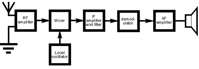
2.4 Receiver
8 Figure 2.2: Block Diagram of Receiver(Mirkin 2013)
2.5 Radio Transmission loss