BUS ALERT SYSTEM (BAS)
MOHAMMAD AZIMI BIN BASARY
This Report is Submitted in Partial Fulfillment of Requirements for The Bachelor Degree of Electronic Engineering (Telecommunication Electronic)
Fakulti Kejuruteraan Elektronik Dan Kejuruteraan Komputer Universiti Teknikal Malaysia Melaka
v
DEDICATION
To my parents,
Basary Bin Omar & Sofiah Binti Abdullah To my siblings
Faizal, Faezah, Hafizah, Shafura, Amirah, Hafiz, Aiman, To my helpful friends
Faiz, Amar, Ruthra, To all my lovely course mates
4-BENT 2011/2015
Thank you for always with my side along to complete this journey, I very appreciate with your support and help.
vi
ACKNOWLEDGEMENT
Alhamdulillah and thanks to Allah S.W.T because I can finish my work for final year project with successfully.
I am very thankful to everyone who all supported me for I have completed my project effectively and moreover on time.
I am equally grateful to my supervisor Pn Nazreen Bt Waeleh. She gave me moral support and guided me in different matters regarding the topic in how to do my
research. She had been very kind and patient while suggesting me the outlines of this project and correcting my doubts. I thank her for her overall supports.
vii
ABSTRACT
viii
ABSTRAK
ix
TABLE OF CONTENT
CHAPTER TITLE PAGES
TITLE OF PROJECT i
DECLARATION ii
DEDICATION iv
ACKNOWLEDGEMENT v
ABSTRACT vi
ABSTRAK vii
TABLE OF CONTENT viii
LIST OF TABLES xi
LIST OF FIGURES xii
LIST OF KEYWORD xiv
I INTRODUCTION 1
1.0 BACKGROUND OF STUDY 1
1.1 BASIS OF PROJECT 3
x
1.3 OBJECTIVE 4
1.4 SCOPE OF STUDY 5
II LITERATURE REVIEW 7
2.0 RESEARCH OF PREVIOUS WORK 7
2.1 RELATED WORKS 11
2.2 MICROCONTROLLER 13
2.2.1 ARDUINO UNO MICROCONTROLLER 14
2.2.2 ARDUINO UNO REV3 15
2.2.3 ATMEGA48PA/ 88PA/ 168PA/ 328P 17 2.3 RF MODULE (TRANSMITTER & RECEIVER) 19
2.4 SOFTWARE DEVELOPMENT 21
2.4.1 ARDUINO SOFTWARE IDE 21
2.4.2 MULTISIM SOFTWARE 23
2.4.3 PS SPICE SOFTWARE 24
2.4.4 PROTEUS SOFTWARE 25
2.4.5 ISIS SOFTWARE 26
2.5 RADIO FREQUENCY (RF) TRANSMISSION 27
III METHODOLOGY 28
3.0 COMPONENTS AND TOOLS IDENTIFICATION 28
3.0.1 PROTOBOARD 29
3.0.2 TRANSMITTER AND RECEIVER 30
3.0.3 DECODER AND ENCODER 31
3.0.4 TESTING RESULTS FOR TX & RX 37
3.1 FLOW CHART 38
3.2 EXPECTED PROBLEM 40
xi
3.4 SOFTWARE DEVELOPMENT 41
3.4.1 ARDUINO SOFTWARE IDE 41
IV RESULTS AND DISCUSSION 42
4.0 PROJECT HARDWARE 42
4.1 PROJECT TEST ON SOFTWARE 44
4.2 PROJECT TEST ON PROTOTYPE BOARD 49
V CONCLUSION AND RECOMMENDATION 51
5.0 INTRODUCTION TO CONCLUSION 51
5.1 PROJECT LIMITATION RECOMMENDATION 52
xii
LISTS OF TABLE
NO TITLE PAGES
2.1 Technical Specifications 15
2.2 Pin Description 20
3.1 Description Transmitter Pin 31
3.2 Description Receiver Pin 31
3.3 Value of Oscillator Resistor 32
3.4 Testing Result 37
3.5 Gantt chart for FYP -1 57
3.6 Gantt chart for FYP -2 57
xiii
LISTS OF FIGURE
NO TITLE PAGES
1.1 Basic Block Diagram of the Bus Alert System (BAS) 3
1.2 System Diagram 4
1.3 Distance between Tx-Transmitter and Rx-Receiver 6
2.1 Arduino Uno R3 15
2.2 Arduino Uno R3 Pin Definition 16
2.3 RF Module (Transmitter & Receiver) 19
2.4 Pin Diagram 20
2.5 Arduino Software IDE for Arduino Uno 22
2.6 Frequency Band 27
3.1 Breadboard 29
3.2 Breadboard with Completed Transmitter and Receiver Circuit 29
3.3 The Length of Antenna is 18cm 30
3.4 Transmitter Module 433 MHz 30
3.5 Receiver module 433MHz 31
3.6 Pin of the Decoder 32
3.7 Pin of Encoder 32
3.8 Block Diagram for Decoder PT2272 33
3.9 Flow Chart Diagram for PT2272 33
3.10 Block Diagram for Encoder PT2262 34
3.11 Flow Chart Diagram for PT2262 35
3.12 Schematic Diagram for Transmitter and Receiver 36
3.13 Methodology of Project 38
xiv
4.1 Completed Circuit Design 43
4.2 Completed RF-Tranmitter (Tx) Circuit Design 43
4.3 Completed RF-Receiver (Rx) Circuit Design 43
4.4 Arduino UNO Test for LCD Display using coding 44 4.5 Arduino UNO Test for LED and Buzer using coding 45
4.6 Arduino UNO Coding for Final Project 46
4.7 Arduino UNO Test for Wrong Coding and Connections 47 4.8 Arduino UNO Test for Correct Coding and Connections 47 4.9 Design and test the circuit used ISIS Software 48 4.10 Circuit for fabricate and itching process used ARES Software 48 4.11 Connection on Prototype Board when testing process 49 4.12 Connection on PCB Board after fabricate and itching process 49 4.13 LCD Display Sreen (LCD1602 Blue Screen with Backlight) 50
xv
LISTS OF KEYWORD
Tx - Transmitter Rx - Receiver
RF - Radio Frequency
GPS - Global Positioning System
GSM - Global System for Mobile Communication RFID - Radio Frequency Identification
IR - Infrared
xvi
LISTS OF APPENDIX
NO TITLE PAGES
A FULL CODING PROGRAMMING OF ARDUINO UNO 55
1
CHAPTER 1
INTRODUCTION
This section gives an overview about the project such as idea of the project and the project‟s background. In this part, the objectives and the scope of the project are explained as well as background of study. This discussion is based on the problem statement of the project. The project title is “Bus Alert System (BAS)”. This project is want to help alert the students about what time the bus is arrived by build the project that used Radio Frequency (RF) transmitter, receiver as the medium to pass and propagate the signal wave when trigger the button at transmitter circuit while Arduino Uno as a microcontroller.
1.0 Background of Study
2
to use RF Transmitter and Receiver as medium for transfer and receive signal. Without RF Transmitter and Receiver, they have to use Infrared (IR) Transmitter and Receiver that only cover small area of coverage propagation. The function of RF Transmitter and Receiver is not only transmit the signal in one direction but it can transmit the signal in any direction and it can cover a large coverage area compared to IR Transmitter and Receiver where the IR Transmitter and Receiver can only transmit the signal in one direction. An RF module (Radio Frequency module) is a small electronic device used to transmit and receive radio signals between two devices. In an embedded system it is often desirable to communicate with another device wirelessly. This wireless communication may be accomplished through optical communication or through Radio Frequency (RF) communication. For many applications the medium of choice is RF since it does not require line of sight. RF communications incorporate a transmitter and receiver.
3
RF communications such as Zigbee, Bluetooth low energy, or Wi-Fi, or they may implement a Proprietary protocol.
The project title is “Bus Alert System (BAS)” at UTeM. Bus alert system is a device used to alert students about what time bus is coming and arrived at bus stop. Currently bus alert system for university uses only timetable or schedule system. However the constraints of timetable system are the university‟s student do not alerted and warned about the arrival of bus. Therefore, in this project a transmitter, a receiver, and an RF technique is proposed due fact that RF signal covers longer distance and reliable. The range of this project is limited to 10-100 meters with the operating frequency of 3-30MHz. The development of the proposed RF remote control consists of designing a transmitter-receiver circuit. A one directional communication concept is applied in transmitting the signal from transmitter circuit to receiver circuit. A reliable and robust RF bus alert system is expected to be developed.
1.1 Basis of Project
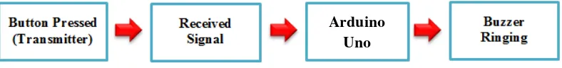
[image:19.595.123.517.597.645.2]The idea of this project is to have a transmitter that will activate the Arduino Uno that already attached with the receiver module. The Arduino Uno Microcontroller will perform the process to take out the output. The buzzer is attached at the output of Arduino Uno. At last, the buzzer is ringing as the output of this project.
Figure 1.1 : Basic Block Diagram of the Bus Alert System (BAS) Arduino
4
1.2 Problem Statement
Bus system at UTeM nowadays, used only timetable or schedule system. This system is not so effective. The constraints of the timetable system are the university‟s student did not alert and warned about the arrival of the bus. This project is wanted to help alert the students about what time the bus is arrived. Students that live at hostel always miss to take the bus to go to class because one or two minutes late. It is because they do not notice about what time bus arrived at bus stop.
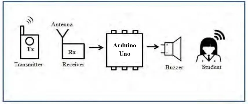
[image:20.595.117.545.341.520.2]Students normally face problem while waiting for the bus especially during rainy day. This is due to the improper shelter in the bus stop as well as there is no fixed drop location. These factors make the student unable to get the bus on a proper time.
Figure 1.2: System Diagram
1.3 Objective
The aim of this project is to develop the bus alert system. This goals can be attained by :
1. Developing a bus alert system that will alert, notice and warn students about what time bus is arrived at bus stop.
First objective is to built a project which implement a system that can help alerted, noticed and warned the students about the arrival of bus at the
5
parking lot. Nowadays, UTeM still use the conventional method which are the schedule and timetable system. The system is not practical to alert the students about what time bus is coming.
2. Designing a circuit for bus alert system.
The second objective is to design a circuit using Multisim and Proteus Software then simulates the design circuit.
3. Developing a coding for Arduino Uno Microcontroller.
The last objective of this project is to develop the code for Arduino Uno. The coding will be stored in Arduino Uno as to control all the process of the project.
1.4 Scope of Study
This study will focus on developing two components of development. There are hardware development and software development. For hardware development, this project will use a RF technique, transmitter, receiver and bell or buzzer. The transmitter and receiver has their own advantage because this electronic device using a wave as a medium to propagate. The nature wave is spread the wave everywhere. Therefore, the transmitter and receiver not limit to one direction only.
6
Figure 1.3: Distance between Tx-Transmitter and Rx-Receiver. Arduino
7
CHAPTER 2
LITERATURE REVIEW
Literature review consists of previous related to the project, information, articles and theories that make up the whole project. This chapter highlights the basic concepts and the fundamental theories of the part that will be used in the project. The main parts which will be discussed in the project are RF Tx-Transmitter, RF Rx-Receiver, Arduino Uno Microcontroller and buzzer or bell.
2.0 Research of Previous Work
8
G.Lavanya ME., Preethy W., Shameem A., Sushmitha A.. “Passenger Bus Alert System for Easy Navigation of Blind”. International Conference on Circuits, Power and Computing Technologies 2013 [ICCPCT-2013]. 2013.
Journal 1 - This journal is about the project of a bus system using wireless
sensor networks (WSNs). The project used ZigBee unit. This project is help the blinds people to recognized and identify the desired bus that the blinds want to take. Besides that, this project can help the blind people to navigate. In addition, this project is also aimed to help the elder people for independent navigation.
Improvement – Based on the journal, the previous project was used