School of Optical-Electrical and Computer Engineering, University of Shanghai for Science and Technology, Shanghai, China 200093
e-mail: [email protected], [email protected]
Abstract
Because of its small size, high reliability, efficiency, and its output torque characteristics, brushless DC motor (BLDCM) had been widely used in many field of robotics, precision instruments and equipment, etc. However, its inherent electromagnetic torque ripple limited the scope of its application, which was the focus and difficulty of its research in recent years. This article first described the causes of brushless DC motor torque ripple, and then torque ripple generated by four PWM modulations was analyzed to get optimum control scheme, finally the MATLAB / SIMULINK simulation model verified the analysis of the results. This paper provided the most intuitionistic exhibition.
Keywords: Brushless DC motor, Torque ripple, MATLAB/SIMULINK
1. Introduction
Brushless DC motor (BLDCM) is one type of permanent magnet synchronous motor, which is wildly used in many fields. It has good speed regulation characteristics, such as high efficiency, long life, low noise, high speed range, good output characteristics and other advantages [1]. The applications of brushless DC (BLDC) motors and drives have grown significantly due to their high power density and easy control method in recent years in the appliance industry and the automotive industry [2].
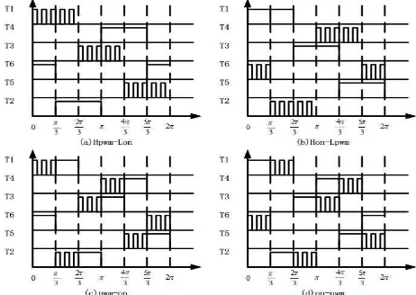
However, it has the disadvantage of torque ripple, and this will reduce the reliability of power transmission system. What mentioned above restricts the applications in the higher accuracy system. The main cause of the drawback is the existence of inductor. Because of the inductor, the current cannot change immediately at the time of commutation. So that it causes the commutation torque ripple. The procedure has been investigated completely in [3]-[4]. What’s more, the existence of induced emf and switching method which, in certain conditions cause the forward bias of diodes connected to inactivephase and lead to current flow in inactive phase and makes torque ripple [5]. Due to the influence of the torque ripple, the hot topic of the present study of BLDM is commutation torque ripple suppression, and the way to suppress the torque ripple is the improvement of PWM mode. Different modulations of PWM used in BLDCM will generate different torque ripple. There are four types of PWM modulation proposed including Hpwm-Lon, Hon-Lpwm, pwm-on and on-pwm. All four modulations can drive the motor successfully, but the problem is which one can generate the lowest torque ripple.
By the calculation, this paper will analyze the influences of four types of PWM mode on the torque ripple during commutation clearly. Four types of result will be compared to find the lowest one. To prove the analysis result, the BLDCM simulation model with different PWM modes will be built in matlab/simulink. Four types of PWM modulation can be applied to the model, simulation result can present the conclusion intuitively and can provide reference for further study of brushless DC motor.
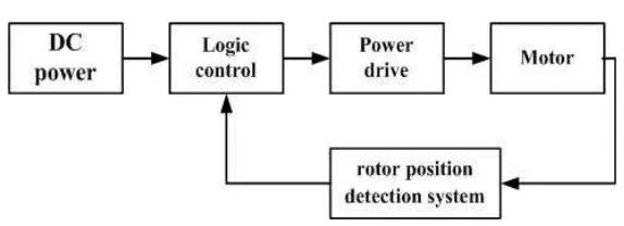
2. Components And Principles of BLDM Control System
Figure 1. Block Diagram of BLDCM Control System
In this control system, power drive unit is a three-phase inverter, it contains six IGBTs. Further more, logic control unit and rotor position detection system are the most important units. The logic control unit will supply the power to each phase winding, and the rotor position detection system contains three hall sensors which can provide the information of rotor position and speed. They can control the order and time of each phase conduction of motor stator, then the average voltage of each phase windings can be controlled. Therefore the system can drive and control the brushless DC motor [6].
3. The Mathematical Model of BLDCM
Assuming that the magnetic circuit is unsaturated, eddy current and hysteresis losses are not considered. Three-phase voltage equation across the motor windings is as follows:
c b a c b a c cb ca bc b ba ac ab a c b a c b a c b a e e e i i i p L M M M L M M M L i i i R R R u u u 0 0 0 0 0 0 (1)
Where
u
a,
u
b,
u
c are the three-phase voltagesi
a,
i
b,
i
care the three-phasecurrents
e
a,
e
b,
e
care the back emfsR
a,
R
b,
R
care the stator resistancesL
a,
L
b,
L
care thestator windings self-inductions
M
ab,
M
ac,
M
ba,
M
bc,
M
ca,
M
cbare mutual-inductions betweenthe two-phase windings of stator;
p
is derivate operatorp
d
/
d
t in (1).Because of three-phase windings are completely symmetrical and the permanent magnet magnetic permeability approximates air, moreover, it is a star wound type. It can can be assumed that three-phase winding inductance and mutual inductance are constant, further- more, they have nothing to do with the rotor position. Then equations can be obtained as follows:
L L L
La b c (2)
M M M M M M
Mab ac bc ba ca cb
(3)
0
b ca
i
i
i
(4)R R R
Ra b c (5)
Considering above three-phase voltage equation is
4. Analysis of torque ripple
There are two main causes of torque ripple,the first is the existence of alveolus, and the second is commutation torque ripple.This paper will focus on the latter.
4.1.Commutation Principle of BLDCM
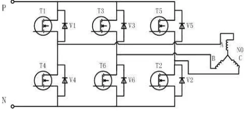
The equivalent circuit of BLDCM is shown in Figure 2. There are six IGBTs in the equivalent model namely T1, T3, T5, T4, T6 and T2. They make up three-phase inverter circuit [7].
Figure 2. the Equivalent Circuit of BLDCM
IGBT will be triggered according to the order that is calculated by the information of rotor position detection system. Only two of three phases are active at any time. The main principle is to let the corresponding phase on when the magnetic field is strongest.
Based on electromagnetic induction principle, the back emf of each phase is:
rlB Ze D (8)
Where
r
is the distance between the stator and the rotor center;l
is the length of the magnet steel;Z
D is the number of the effective conductors about stator single-phase;B
is magnetic induction intensity;
is the electrical angular speed of rotor.Figure 3. The Rule of Commutation
4.2. Cause of commutation torque ripple
In an ideal situation, back EMF waveform is trapezoidal, the width of its flat-top is 120 electrical angle. At the same time, the phase current waveform is rectangular whose width is also 120 electrial angle. Once the state is not like that, it will generate the torque ripple [8].
In a real–world situation, the existence of inductors make the current cannot change immediately, hence the the back EMF waveform or current waceform is not like that in an ideal situation.So that it is the cause of the commutation torque ripple.
The variation of current and torque during the process of commutation is shown in Figure 4 in detail. In [9]-[11], the variation of current corresponding to different conditions was discussed in detail.
Figure 4. waveform of current and torque during commutation
5. Influences of PWM Modes on The Torque Ripple
Figure 5. Single-chop PWM Control Modulation
5.1. Analysis of The Commutating Process of Upper Bridge-arms
Considering the circuit in Figure 2, the commutation process from T1T2 state to T3T2 state will be analyzed, that is to say T1 commutate to T3. In the process of commutation, parasitic diode V4 is in a state of stream.
(1) Hpwm-Lon and pwm-on modulation
According to Figure 5, the states during the commutation under Hpwm-Lon and pwm-on modulation are same. In the process of commutation, parasitic diode V4 is in a state of stream, T3 is given PWM signal and T2 keeps on. Thus these two kinds of PWM modulation go into the same category to be analyzed.
Assuming that the terminal voltage of three-phase inverter is
U
d.Considering Figure 2, the voltage of A phase is 0V for the parasitic diode V4 is in a state of stream because of T3 PWM signal. The voltage of B phase isU
d when T3 is on and the voltage of phase B is 0Vwhen T3 is off. So that the voltage of B phase can be assumed as
DU
d (D is duty radio of PWM signal). Then the voltage of C phase is 0V by reason of that T2 keeps on. Based on (6) three-phase voltage equations can be deduced as follows: N N N N N N c b a c b a c b a d U U U e e e i i i p M L M L M L i i i R R R DU 0 0 0 0 0 0 0 0 0 0 0 0 0 0 0 0 0 (9)
Where
U
NN0 is the voltage of neutral point in (9). Considering Figure 3,
e
b
e
c
k
when T3T2 is on. At the same time, it can be assuming that
e
a
k
for the commutation timeis short. Combining (4) and (9) , the voltage of neutral point is:
k
DU
U
N N d3
1
3
1
0
(10)
)
3
4
(
)
(
3
1
)
3
2
2
(
)
(
3
1
)
3
2
(
)
(
3
1
c d c b d b a d aRi
k
DU
M
L
dt
di
Ri
k
DU
M
L
dt
di
Ri
k
DU
M
L
dt
di
(11)According to the analysis, it can be known that
i
a(
0
)
i
c(
0
)
i
0,
i
b(
0
)
0
beforecommutation. At the same time, the resistance of winding can be ignored when the frequency of PWM signal is high. Considering (11), approximate value of three-phase current is:
t
k
DU
M
L
i
i
t
k
U
M
L
i
t
k
DU
M
L
i
i
d c d b d a)
4
(
)
(
3
1
)
2
2
(
)
(
3
1
)
2
(
)
(
3
1
0 0
(12)Combined with (12) and (7),the electromechanical torque of BLDCM during commutation can be derived:
t
k
DU
M
L
k
n
ki
n
T
d pp
(
2
8
)
)
(
3
2
01
(13)
The electromechanical torque of BLDCM before commutation is:
0
0
(
e
i
e
i
e
i
)
2
n
ki
n
T
p a a
bb
cc
p
(14)Compared (13) with (14), the value of the torque ripple can be obtained as
t
DU
k
M
L
k
n
T
T
T
p(
8
2
d)
)
(
3
1 0 1
(15)(2) Hon-Lpwm and on-pwm modulation
It is same as the previous section. According to figure 5, the states during the commutation under Hpwm-Lon and pwm-on modulation are same. In the process of commutation, parasitic diode V4 is in a state of stream, T2 is given PWM signal and T3 keeps on. Thus these two kinds of PWM modulation go into the same category to be analyzed.
Considering figure 1, like that in previous section the voltage of three phase can be obtained as
u
a
0
V
,u
b
U
d,u
c
(
1
D
)
U
d.D is also the duty radio of PWM signal. Like the analytic procedure adopted above, the electromagnetic torque during the commutation process is: t DU U k M L k n T TT p (8 2 d 4 d)
) ( 3
2 0
2
(16)Hence the result of analysis is:
2
1
T
T
Obviously, the commutation torque ripple of Hpwm-Lon and pwm-on modulation is lower than that of Hon-Lpwm and on-pwm modulation during the commutating process of upper bridge-arms.
5.2. Analysis of the Commutating Process of Lower Bridge-arms
Considering the circuit in figure 2, the commutation from T1T6 state to T1T2 state, that is to say T6 commutate to T2 will be analyzed. In the process of commutation, parasitic diode V3 is in a state of stream, Like the analytic procedure adopted above, the torque ripple during the commutation process can also be calculated as follow:
(1) Hpwm-Lon and on-pwm modulation
t
DU
U
k
M
L
k
n
T
T
T
p(
8
2
d4
d)
)
(
3
3 0
3
(18)(2) Hon-Lpwm and pwm-on modulation:
t
DU
k
M
L
k
n
T
T
T
p(
8
2
d)
)
(
3
4 0
4
(19)Compared (18) with (19), the torque ripple is as follows
0
)
1
(
)
(
3
2
)
2
8
(
)
(
3
)
4
2
8
(
)
(
3
4 3
D
M
L
t
kU
n
t
DU
k
M
L
k
n
t
DU
U
k
M
L
k
n
T
T
d p
d p
d d
p
(20)
Then the result of analysis is:
4
3
T
T
Thus, during the commutating process of lower bridge-arms, the commutation torque ripple of Hon-Lpwm and pwm-on modulation is lower than that of Hpwm-Lon and on-pwm modulation. So far, conclusion is that the commutation torque ripple with pwm-on mode during commutation is the lowest among all four modes.
6. MATLAB/SIMULINK Simulation Model
control system is shown in Figure 6. In this analysis, the simulation parameters were set as follow. The stator winding resistance
R
2
.
875
The stator winding inductancemH
L
8
.
5
; the inertia momentJ
8
10
4kg
m
2; Pole pairsp
2
;DC bus voltage was 500V; Given speed was 3000rad/s. At last, the load torque changed from0
N
m
to3
N
m
after 0.5 second.
In this simulation model , the pwm unit contained two components such as the HALL unit and the pwm control. The function of HALL unit was to receive the information of the rotor position.With the information, the timing of comutation could be achieved. Following that was pwm control unit.In this unit PWM modulation could be changed to observe the variety about the torque waveform.
Figure 6. Simulation Model of BLDCM
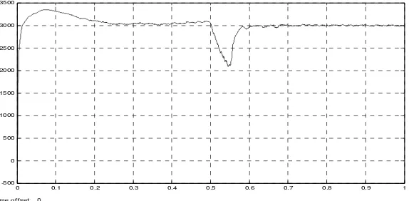
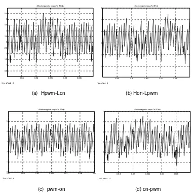
7.Simulation Result
The simulation result of the BLDCM model is shown in Figure 7. It is the speed waveform. As shown obviously, the motor went into steady state after 0.2 second and speed arrived at the given value. Because of the fluctuation of load torque, the speed fluctuated at 0.5 second. Then the speed returned to the stable state after less than 0.2 second. So far, it gave a conclusion that the simulation model of BLDCM is a steady control system.
0 0.1 0.2 0.3 0.4 0.5 0.6 0.7 0.8 0.9 1
-500 0 500 1000 1500 2000 2500 3000 3500
Figure 7. the Waveform of Simulation Result
0.915 0.92 0.925 0.93 0.935 0.5
1 1.5 2
0.915 0.92 0.925 0.93 0.935
1 2
(a) Hpwm-Lon (b) Hon-Lpwm
0.91 0.915 0.92 0.925 0.93 0.935 0.94
0 1 2 3 4 5
<Electromagnetic torque Te (N*m)>
0.915 0.92 0.925 0.93 0.935
1 2 3 4 5
6 <Electromagnetic torque Te (N*m)>
(c) pwm-on (d) on-pwm
Figure 8. The Waveform of torque
Viewing Figure(a), Figure(b), Figure(c) and Figure(d) in Figure 7, it is obviously to see that the waveform corresponding to pwm-on modulation is the most steady (without burr )among all modes. As the analysis above, the commutation torque ripple with pwm-on mode during commutation is the lowest among all modes. Thus the pwm-on modulation is the best selection in BLDCM control system.
8. Conclusion
This paper described the basic components of the BLDCM control system, it consisted of DC power, logic control, power drive, rotor position detection system and motor. Then the mathematical model of BLDCM and the rule of commutation were analyzed, on that basis the conclusion was obtained that the existence of winding inductance was the cause of commutation torque. Specific reason was that the current cannot change immediately during commutation. Thus it make the torque waveform fluctuate. Furthermore, according to the analysis the way to suppress ripple torque was the improvement of PWM mode.
Based on the analysis above, the commutation torque ripple corresponding to Hpwm-Lon modulation, Hon-Lpwm modulation, pwm-on modulation and on-pwm modulation were calculated. After computation it was known that the commutation torque ripple with pwm-on mode during commutation was the lowest among all four modes.
which was used to vertify the result is very simple and pratical, it will help us understand the content better.Other paper only presented the theoretical analysis, but this article let us see the existence of torrque ripples clearly. Meanwhile the difference of the results were shown intuitively.
Acknowledgements
The research project was supported by the Hujiang Foundation of China (B1402/D1402) and National 863 plan of China under Grant No. 2012AA050206.
References
[1] Seyed MM, Seyed SSG, Seyed MHM. Investigating the Effect of Different PWM Modes on Ripple Reduction in Five-Phase BLDC Motor with New Method. TELKOMNIKA Indonesian Journal of Electrical Engineering. 2014; 12(7): 5129-5136.
[2] Joong HS, Ick C. Commutation torque ripple reduction in brushless DC motor drives using a single DC current sensor. IEEE Trans Power Electronics. 2004; 19: 312-319.
[3] Yong KL, Yen SL. Pulse-width Modulation Technique for BLDCM Drives to Reduce Commutation Torque Ripple without Calculation of Commutation Time. Energy Conversion Congress and Exposition (ECCE). 2011; 47(4): 4398-4404.
[4] Gwang HK, Seog JK, Jong SW. Analysis of the Commutation Torque Ripple Effect for BLDCM fed by HCRPWM – VSI. Applied Power Electronics Conference and Exposition, 1992. APEC '92. Seventh Annual . 10.1109/APEC. 1992; 228401 : 277–284.
[5] W Kun, Hu Cheng, Z Chao. A novel PWM scheme to eliminate the diode freewheeling in the inactive phase in BLDC motor. Chinese Society for Electrical Engineering. 2006: 194-198.
[6] Kwon BH, Min BD. A fully software-controlled PWM rectifier with current link. IEEE Trans Ind Elec. 1993; 40(3): 355-363.
[7] Auzani J, Tole S. MATLAB/SIMULINK Based Analysis of Voltage source Inverter with Space Vector Modulation. TELKOMNIKA (Telecommunication Computing Electronics and Control). 2009 ; 7(1): 23– 30.
[8] R Carlson, M Lajoie-Mazenc, JCDS Fagundes. Analysis of torque ripples due to phase commutation in brushless Dcmachines. IEEE Trans. Ind. 1992; 28(3): 632-638.
[9] Renato C. Analysis of Torque Ripple Due to Phase Commutation in Brushless dc Machines. IEEE Transactions on industry appliation. 1992; 28(3): 632-638.
[10] M Lajoie M, B Nogarede, JC Fagundes. Analysis of torque ripple in electronically commutated permanent magnet machines and minimization methods. Electrical Machines Drives (London). 1989: 85-89.
[11] T Li, G Slemon. Reduction of cogging torque in permanent magnet motors. IEEE Trans. 1988; 24(6): 2091-2903.
[12] Liu M, Guo H. Ripple Torque Analysis and Simulation of BLDC Motor With Different PWM Modes. 2012 IEEE 7th International Power Electronics and Motion Control Conference - ECCE Asia. 2012; 2: 973-977.
![Figure 4 in detail. In [9]-[11], the variation of current corresponding to different conditions was The variation of current and torque during the process of commutation is shown in discussed in detail](https://thumb-ap.123doks.com/thumbv2/123dok/238576.502504/4.595.202.392.396.560/figure-variation-corresponding-different-conditions-variation-commutation-discussed.webp)